http://www.diva-portal.org
Postprint
This is the accepted version of a paper published in Composites. Part A, Applied science and manufacturing. This paper has been peer-reviewed but does not include the final publisher proof-corrections or journal pagination.
Citation for the original published paper (version of record):
Esmaily, M., Mortazavi, N., Svensson, J-E., Halvarsson, M., Wessén, M. et al. (2016)
A new semi-solid casting technique for fabricating SiC-reinforced Mg alloys matrix composites. Composites. Part A, Applied science and manufacturing
Access to the published version may require subscription. N.B. When citing this work, cite the original published paper.
Permanent link to this version:
Elsevier Editorial System(tm) for Composites Part A
Manuscript Draft
Manuscript Number:
Title: A new semi-solid casting technique for fabricating SiC-reinforced Mg alloys matrix composites
Article Type: Research Paper
Keywords: Metal-matrix composites (MMCs); Microstructure; Magnesium alloys; Casting.
Corresponding Author: Mr. Mohsen Esmaily,
Corresponding Author's Institution: Chalmers University of Technology First Author: Mohsen Esmaily
Order of Authors: Mohsen Esmaily; Nooshin Mortazavi; Jan-Erik Svensson; Mats Halvarsson; Magnus Wessen; Lars-Gunnar Johansson; Anders Jarfors Abstract: The capability of the newly developed rheocasting (RC) technique in combination with the RheoMetal process for producing SiC particulate-reinforced AM50 and AZ91D matrix composites (Mg-based MMCs) was investigated. The quality of the MMCs was studied by analyzing the fraction of casting pores, number density of SiC clusters and the
uniformity of SiC particles. Solid fraction, particle size and oxidation of SiC particles had strong impacts on the overall quality of the MMCs. The MMCs produced by 40% solid fraction and oxidized micron-sized SiC particles exhibited an excellent casting quality. A low-quality MMC was obtained when non-oxidized sub-micron sized SiC particles were employed. The results showed the formation of various types intermetallic particles and carbides such as MgO, Mg2Si, Al2MgC2, Mg2C3, Al4C3 as the interfacial reaction products of SiC/Mg alloy's melts. Mg hydride (α-MgH2) was also identified in inter-dendritic regions of the MMCs for the first time. Suggested Reviewers: Manoj Gupta
National University of Singapor mpegm@nus.edu.sg
Expert in Mg-based composites Zhongyun Fan
Director of BCAST (UK) zhongyun.fan@brunel.ac.uk Hari Babu
Brunel University
hari-babu.nadendla@brunel.ac.uk Hiroyuki Fukuda
Graduate School of Engineering, Osaka University fukkun-fukuda@jwri.osaka-u.ac.jp
HAI ZHI YE
Dear Editor: 15th Oct. 2015
Please find the attached manuscript entitled '' A new semi-solid casting technique for fabricating SiC-reinforced Mg alloys matrix composites'' for your kind review.
This paper reports a successful fabrication of Mg-based composites using the newly developed semi-solid casting technique for the first time. We performed both qualitative and quantitative analyses on the microstructure of the cast MMCs. Three different casting trials using different ceramic reinforcements and different casting parameters were performed to produce different types of composites. All the probable phases in Mg-SiC system were identified. Optimized casting parameters are reported. The usefulness of this casting method for producing Mg-based composites were discussed in terms of the resulting material quality. The authors declare the novelty of the work. I do hope you kindly consider this manuscript as an appropriate article for this journal.
Kindest regards, Mohsen Esmaily,
Chalmers University of Technology Gothenburg, Sweden.
1 2 3 4 5 6 7 8 9 10 11 12 13 14 15 16 17 18 19 20 21 22 23 24 25 26 27 28 29 30 31 32 33 34 35 36 37 38 39 40 41 42 43 44 45 46 47 48 49 50 51 52 53 54 55 56 57 58 59 60 61
A new semi-solid casting technique for fabricating
SiC-reinforced Mg alloys matrix composites
M. Esmailya,
*, N. Mortazavib, J.E. Svenssona, M. Halvarssonb, M. Wessénd, L.G. Johanssona and A.E.W. Jarforsc
a Department of Chemistry and Chemical Engineering, Chalmers University of Technology, SE-412 96 Gothenburg, Sweden b Department of Applied Physics, Chalmers University of Technology, SE-412 96 Gothenburg, Sweden c Department of Materials and Manufacturing - Casting, Jönköping University, SE-551 11 Jönköping, Sweden
Abstract
The capability of the newly developed rheocasting (RC) technique in combination with the RheoMetal process for producing SiC particulate-reinforced AM50 and AZ91D matrix composites (Mg-based MMCs) was investigated. The quality of the MMCs was studied by analyzing the fraction of casting pores, number density of SiC clusters and the uniformity of SiC particles. Solid fraction, particle size and oxidation of SiC particles had strong impacts on the overall quality of the MMCs. The MMCs produced by 40% solid fraction and oxidized micron-sized SiC particles exhibited an excellent casting quality. A low-quality MMC was obtained when non-oxidized sub-micron sized SiC particles were employed. The results showed the formation of various types intermetallic particles and carbides such as MgO, Mg2Si, Al2MgC2, Mg2C3, Al4C3 as the interfacial reaction products of SiC/Mg alloy’s melts. Mg hydride (α-MgH2) was also identified in inter-dendritic regions of the MMCs for the first time.
Keywords; Metal-matrix composites (MMCs); Microstructure; Magnesium alloys; Casting.
*Corresponding author at: Department of Chemistry and Chemical Engineering, Chalmers University of Technology, SE-412 96 Gothenburg, Sweden
Email address: mohsen.esmaily@chalmers.se
Phone: 0046-317722864
Manuscript
1 2 3 4 5 6 7 8 9 10 11 12 13 14 15 16 17 18 19 20 21 22 23 24 25 26 27 28 29 30 31 32 33 34 35 36 37 38 39 40 41 42 43 44 45 46 47 48 49 50 51 52 53 54 55 56 57 58 59 60 61
1. Introduction
Metal matrix composites (MMCs) are an emerging class of new materials that are being developed to improve the service performance of matrix metals and alloys. High-quality MMCs offer superior mechanical properties compared to their monolithic counterparts. They exhibit increased stiffness, tensile and fatigue strength, improved creep resistance and high temperature properties and increased wear resistance [1, 2]. Magnesium (Mg) alloys combine high specific strength with good castability and excellent machinability and offer several advantages in relation to weight reduction and energy savings [3]. Combining MMC technology with Mg alloys seems to provide the advantages of both MMCs and Mg alloys, and hence are known to be very encouraging. MMCs based on Mg and Mg alloys matrices (Mg-MMC) are exceptional candidates for engineering lightweight structural materials, and are of great technological importance for many engineering applications, such as automotive and aerospace industries [4]. In general, Mg-MMCs are reinforced by various ceramic particles such as SiC, Al2O3, Mg2Si and carbon nanotubes; see for example [5-9]. They have been fabricated using a variety of methods such as stir casting [10], gas pressure infiltration [11], powder metallurgy [12, 13], squeeze casting [14], spray deposition [15], injection molding [16] and in-situ techniques [17].
As an alternative to conventional casting methods, semi-solid metal (SSM) processing has shown the potential to produce Mg castings with a high level of complexity with a laminar flow of metal during mold filling [18]. This is the result of the higher viscosity of the semi-solid material, and reduces air entrapment compared to conventional casting methods, thereby produces castings with improved mechanical properties [19]. This paper deals with the microstructure of Mg-MMCs of two Mg alloys, namely alloy AM50 and AZ91D MMC produced through rheocasting (RC) technique which is a subcategory of SSM processing. RC is a casting process that offers cast components with very low pore content and high strength when a strict temperature control is achieved [20]. One promising method for preparing the slurries for the RC technique is the newly developed RheoMetal process, which is also known as the Rapid Slurry Formation (RSF) process [20, 21]. The RheoMetal process converts a molten metal into slurry using internal enthalpy exchange between the liquid metal at relatively low superheat and a piece of solid metal attached to a stirrer. It has been shown that the RC method combined with the RheoMetal process has the potential to produce high quality AM50 and AZ91D Mg alloys with low casting defects [21, 22] and that the environmental properties of Mg alloys can be notably mitigated by tailoring the microstructure through the component fabrication step using the RC technique.
The casting microstructure of Mg-MMCs is crucial to their performance in service. The main challenge may be to judiciously optimize the casting process to achieve uniformity and reproducibility provided that the host alloy and the reinforcement are suitable. Despite an abundance of research on Mg-MMC fabrication using conventional casting techniques, there very are few reports [23-26] dealing with the use of SSM processing, also known as ''compocasting'', to produce this class of materials, and there are no published works on the use of RC and RheoMetal processes to fabricate Mg-MMCs. The objective of this investigation is therefore to document the influence of RC process on the microstructure of Mg alloy RC AM50- and AZ91D-based MMCs using two separated experiments. We first produced MMCs using non-oxidized nano-sized SiC particles, as a complex system, to analyze the formation of various types of intermetallic particles that may form during solidification in SiC-reinforced Mg alloys. In the second experiment, we examined the capabilities of RC process in producing sound Mg alloys-based MMCs using two different solid fractions through
1 2 3 4 5 6 7 8 9 10 11 12 13 14 15 16 17 18 19 20 21 22 23 24 25 26 27 28 29 30 31 32 33 34 35 36 37 38 39 40 41 42 43 44 45 46 47 48 49 50 51 52 53 54 55 56 57 58 59 60 61
quantitative assessments of the MMCs’ microstructures. Thus, the uniformity of SiCparticles, casting defects and microstructure of the host alloys were characterized using image analysis techniques.
2. Experimentation
2.1. Fabrication of SiC-reinforced MMCs
The RC AM50, AZ91 and Mg-MMCs were produced using the RC process, see the schematic illustration of the casting procedure in Fig. 1. The casting machine was manufactured by Suzhou Sanji Foundry Co Ltd. The machine had a locking force of 50 tonnes. The die had a projected area of 250 cm², making it possible to produce cast components having wall thicknesses of 7, 12 and 20 mm. The slurry for the RC process was prepared using the RheoMetal process, where a molten metal is converted into slurry using internal enthalpy exchange material (EEM) between the liquid metal at relatively low superheat and a piece of solid metal attached to a stirrer. The EEM was cast onto a steel rod. The rod was then immersed into the melt while stirring after it had been cooled down to a moderate temperature. During this process, the melt was cooled down rather quickly during the melting of the EEM, and at the end, homogeneous slurry was prepared. An advantage of the RheoMetal process has already been discussed in [20-22, 27, 28]. In this way, the solid fraction (fs)
can be easily controlled in a robust way by the initial temperatures of the melt and the EEM as well as the EEM to melt ratio. Control of the fs was necessary to be able to meet the requirement that the
slurry be pourable into the shot sleeve of a die casting machine.
Commercial Mg alloys AZ91D and AM50 alloys were used as the matrices. Their chemical compositions were analyzed through optical mass spectroscopy and are listed in Table 1. In the present investigation, the MMCs were produced using two different SiC particle sizes and two different fs values. Two different procedures that were employed for making the composites are
described in Table 2. In the first experiment, Mg alloy AM50 and AZ91D were reinforced with SiC particles in the size range 0.1-1.9 µm (with the commercial name: HCS 59N) using an fs of 60%. In the
second experiment, Mg alloy AZ91D was reinforced with bigger SiC particles in the size range 4-28 µm (with the commercial name: HCS 400) at two fs values of 30 and 60%. In addition, we oxidized the
larger SiC particles prior to casting at 1100ºC for 45 minutes. In both sets of experiments, Mg alloy matrix composites were reinforced with 10 vol.% of high purity SiC particles. More details regarding the process parameters, including the stirring time, stirring speed, and protection of the slurry, are listed in Table 2.
2.2. Material characterization techniques
As-cast materials were cut into cross-sections of the RC AM50 and AZ91D as well as the Mg alloys-based MMCs with an area of about 4.2 mm2 for microstructural characterization. The sectioned samples were mounted in cold-setting epoxy resin. The mounted samples were then ground, lubricated with de-ionized water, with successive grades of silicon carbide abrasive papers (SiC grit papers) from P800 to P4000 mesh. Polishing was then performed using cloth discs and diamond paste in sizes ranging from 3 to 1 µm, followed by a fine polishing step using OPS colloidal silica for 120 s on a Buehler Microcloth. The specimens were cleaned with distilled water, degreased with acetone, washed again with distilled water, and dried by cool air with a blower. They were then stored in a desiccator before and during examinations. Considering the difficulties associated with the microstructural quantification in the cast Mg-Al alloys, both polished and etched samples were investigated. A solution of Nital (5 ml HNO3 + 95 ml ethanol) was used as the etchant to reveal the microstructure. An
1 2 3 4 5 6 7 8 9 10 11 12 13 14 15 16 17 18 19 20 21 22 23 24 25 26 27 28 29 30 31 32 33 34 35 36 37 38 39 40 41 42 43 44 45 46 47 48 49 50 51 52 53 54 55 56 57 58 59 60 61
Olympus GX-71 optical microscope (OM) and a FEI Quanta 200 environmental scanning electron microscope (ESEM) equipped with energy dispersive x-ray (EDX) micro-analysis hardware were used for imaging. The instrument comes equipped with an Oxford Inca EDX with a Silicon Drift Detector (SDD) (Beryllium window). The EDX analysis was carried out using 15 kV accelerating voltage. The grain size measurements were carried out based on the Feret diameter that is defined as the distance between two parallel tangential lines rather than planes [29]. The aspect ratio of grains in the materials was calculated using F = 4 πA/P2, where A is the area and P is the peripheral length of a grain.
Quantitative characterization was performed using statistical analyses in order to examine the grain size and fraction of casting pores. Different types of software, namely Adobe Photoshop CS4, Image Pro-Plus and ImageJR were used for scrutinizing micrographs. The uniformity of SiC particulates was investigated using the nearest neighbor distance (NND) distribution function and the quadrat method. The NND function was used to describe the arrangement of SiC clusters (≥ 40 µm) in a quantitative manner. The NND is a probability density function such that P(r) dr is the probability of finding the nearest neighbor of a particle with the same characteristics in the distance range r to (r+ dr); see [22, 30] for more details. The quadrat method was chosen to study the distribution of SiC particles, see [31, 32]. The quadrat method was used for the samples containing bigger SiC particles and much less clustering. To do this, the SEM micrographs were divided into square cells and the number of SiC particulates in each quadrat, Nq, was counted. In general, an ordered particle distribution would be expected to generate a large number of quadrats containing approximately the same number of particles. On the other hand, a clustered distribution would be expected to produce a combination of empty quadrats, quadrats with a small number of particles, and quadrats with many particles. A random distribution would be expected to produce results somewhere in between these two extremes. In this study, the quadrat method was carried out on 25 micrographs within square fields, 600 × 600 pixels in size. Each field was divided into 225 contiguous quadrats. A quadrat size of 40 × 40 pixels was selected. The calculated particles number per cell distributions were then compared to the two theoretical distributions; (a) the Poisson distribution (Equation 1) and (b) the negative binomial distribution (Equation 2) according to the followings [32];
P(r) = exp (-µ) Equation (1) P(r) =
Equation (2)
where P(r) indicates the probability, r denotes the number of particles per cell, µ is the mean value of the number of particles per cell, and k and p are parameters that can be determined according to [32]. According to the above two types of distribution, the Poisson distribution corresponds to a homogenous particle distribution and the negative binomial distribution corresponds to a clustered type of particles distribution. To examine the effect of oxidation on the composition of the surface film formed on SiC particles high-resolution Auger electron spectroscopy (HR-AES) was employed. Analysis was performed in a site-specific manner on large SiC particles. The analyses were conducted using a Physical Electronics Model 700 Scanning Auger Nanoprobe (LS) apparatus equipped with a spherical sector analyser. Spectra were recorded in direct mode and with a 2-5 keV and 1 nA primary beam.
Transmission Electron Microscopy (TEM) was employed to shed light on the microstructure of Mg alloy AZ91D-based MMC using a Titan 80-300 TEM/STEM instrument operating at 300 kV. The microscope was equipped with an Oxford Inca EDX detector. An FEI Versa 3D combined Focused Ion Beam/Scanning Electron Microscope (FIB/SEM) workstation was used to create and investigate
1 2 3 4 5 6 7 8 9 10 11 12 13 14 15 16 17 18 19 20 21 22 23 24 25 26 27 28 29 30 31 32 33 34 35 36 37 38 39 40 41 42 43 44 45 46 47 48 49 50 51 52 53 54 55 56 57 58 59 60 61
cross-sections of the oxide scales and subjacent metal of the exposed samples. The thin lamella was mounted on a support Cu-grid. Time-resolved low-loss electron energy loss spectroscopy (EELS) was performed on FIB-prepared TEM thin foils of the Mg-based MMCs using a monochromated and aberration-corrected transmission electron microscope at 80 kV. Finally, micro-Vickers hardness was measured (Akashi HV-114) on the polished surfaces of the samples. The mean values of 20 measurements were obtained under the condition of a 0.1 kgf load with a duration of 15 sec.
3. Results
3.1. RC AZ91D and AM50 microstructures
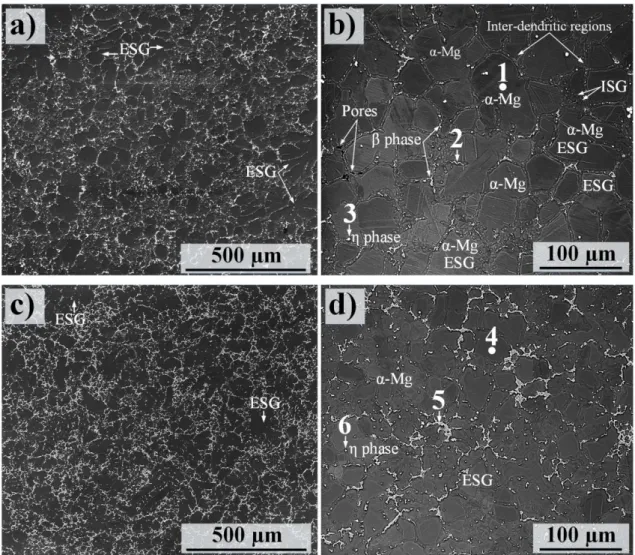
The microstructural constituents of the cast Mg-Al alloys, especially AM50 and AZ91D, have been widely studied by numerous authors; see for example [33-35]. The main microstructural constituents are α-Mg grains (hexagonal; P63/mmc, a = 0.32 nm, c = 0.521 nm) surrounded by inter-dendritic regions (also called eutectic α) and β phase particles (Mg17Al12 cu ic m, a = 1.056 nm). Owing to the presence of Mn, Mg-Al alloys in the AM and AZ series also contain a small amount of η phase particles (Al8Mn5-xFex) [22, 28]. Moreover, transient phases such as Mg5Al have been reported in the microstructure of alloy Mg-Al alloys [28]. This is a precursor of -Mg17Al12 and has considerably lower volume fraction than the dominant intermetallic phase particles. Figure 2 shows SEM
micrographs of the microstructure of RC Mg alloys AM50 and AZ91D. SEM/EDX of the main microstructural constituents in the RC materials are provided in Table 3. Both microstructures
consisted of externally solidified dendritic grains (ESGs) and finer grains designated internally solidified grains (ISGs). The ESGs are large grains that are usually formed prior to the melt entering the casting and in the shot-sleeves. However, ESGs can also be fragmented during their passage through the gating system [22].
In oth cases the β phase component appeared in the inter-dendritic regions. As expected, a comparison of the microstructures produced by RC AM50 and AZ91 showed that the β phase tended to form relatively fine particles in RC AM50 while the β phase particles in the RC alloy were coarser and more continuous and appeared with a higher area fraction. The average α-Mg grain sizes of RC AM50 and AZ91D were calculated to be ~ 45 and 25 µm, respectively. Using electron backscattered diffraction (EBSD) technique, we have previously shown than the RC process produces a semi-dendritic grain structure with a higher aspect ratio compared to those produced by conventional high pressure die-casting (HPDC) [22]. The aspect ratio of α-Mg grains in the alloy matrices was calculated to be 0.69 and 0.72 for the RC AM50 and AZ91D, respectively.
Table 3 represents the EDX point analyses performed at six positions in the microstructure of RC AM50 (points 1, 2 and 3) and AZ91D (points 4, 5 and 6) designated in Fig. 2. The center of the α-Mg grains contained ~ 1.8 and 2.9 at.% Al in RC AM50 and AZ91D, respectively; see P1 and P4. The EDX analysis showed that the phase particles in both RC and HPDC AM50 exhibited an Al concentrations somewhat lower than the eutectic composition, see the binary Mg-Al phase diagram [37]. The detection of less Al content in β particles in Mg-Al alloys by SEM/EDX stems from the fact that the EDX detector is normally affected by the surrounding matrix [22]. Thus, detect more Mg and less Al content is usually expected when analyzing the intermetallic particles by EDX. In addition, the EDX analyses revealed the presence of small amount of Zn in the phase intermetallic compounds, presumably through replacement of Al atmos. The brightest particles (designated as P3 and P6 in
Table 3) in the SEM images (Figs. 2b and d), were η phase particles that mainly contain Al and Mn. It may be noted that Fe was present in the η intermetallic particles. Hence, the solidification
1 2 3 4 5 6 7 8 9 10 11 12 13 14 15 16 17 18 19 20 21 22 23 24 25 26 27 28 29 30 31 32 33 34 35 36 37 38 39 40 41 42 43 44 45 46 47 48 49 50 51 52 53 54 55 56 57 58 59 60 61
microstructure of the fabricated RC AM50 and AZ91D also contained Al8 (Mn5-xFex) intermetallic particles in which Fe replaced some of the Mn atoms.
3.2. SiC-reinforced AM50 and AZ91D microstructures
Figure 3 depicts the morphology and size distribution of the two types of SiC particles used to fabricate the Mg alloys-based MMCs. The particle size distribution (PSD) of the particles was determined through image analysis on high-magnification SEM micrographs. It was clear that there was a huge difference in the size of the two types of particles used in this study.
In the case of HCS 59N, PSD analyses revealed that 85% of the particles are in the range 0.4-1.2 µm with an average particle size of about 0.7 µm. A low percentage of particles (~ 2.2%) was in the nanometer range, showing an average size of less than 100 nm. In the case of the SiC particle type HCS 400, particles exhibited an average size of about 13.1 µm, approximately 19 times bigger than the type HCS 59N. Besides, there were some fractions of particles having an average size in the range 25-40 µm.
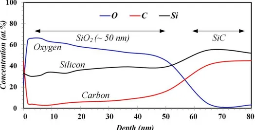
It has been reported that heating SiC particles up to 900°C, not only helps elimination of surface impurities and in the desorption of gases, but also changes the surface composition by forming an oxide layer on the surface [38]. Figure 4 shows an AES depth profile acquired from the surface of large oxidized SiC particle type HCS 400 artificially oxidized at 1100ºC. Three AES analyses were conducted on particles larger than 5 µm in order to determine the thickness of the oxide layer formed on SiC particles. From the profile, the outmost layer of the analyzed particles contained high concentration of C. This layer was observed in all three particles and is attributed to surface contamination. Below this layer, silica (SiO2) was present. The thickness of this layer was found to vary 30-50 nm from one particle to another, probably in relation to the particle surface exposed to electron beam. Such variations in the oxide layer thickness have also been reported in other studies, where this behavior is explained by the fact that oxidation is strongly governed by the surface exposed to O, being faster for the C face than for the Si face [38, 39]. As indicated above, the oxidized particles were employed in the second experiment.
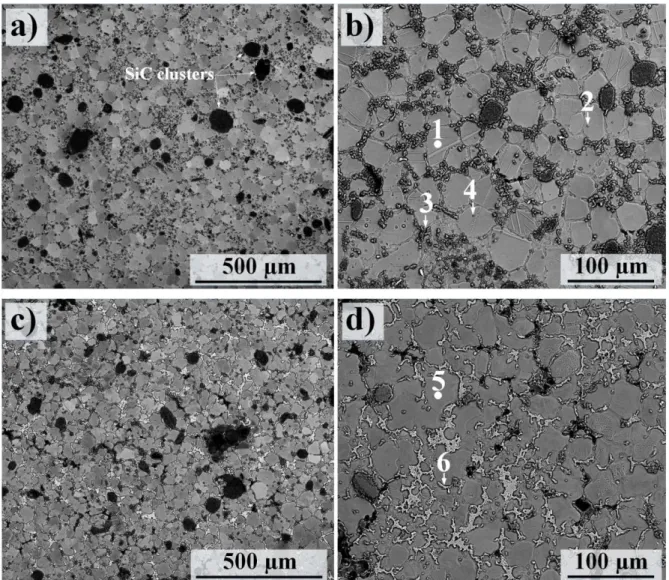
The first experiment- non-oxidized HCS 59N SiC particles: Figure 5 shows the microstructure of the Mg alloy AM50 and AZ91D reinforced by SiC particles type HCS 59N using the RC method. These alloys were produced using an fs of 60%. In this experiment, SiC particles were not oxidized and just
pre-heated to 50ºC for drying. As seen in the SEM images, in both AM50- and AZ91D-based MMCs, SiC clusters could frequently be observed. Quantitative data on the quality of the alloys and MMCs and the particles’ uniformity are provided elow
In the case of ally AM50-based MMC (Figs. 5a and b), morphological inspections revealed that the addition of SiC particles introduced some changes in the grain structure of the alloys. Firstly, a notable reduction in the average α-Mg grain size reaching a value of about 28 was observed in alloy AM50-based MMC. This can be compared to the average α-Mg grain size in the RC AM50, compare Fig. 5b
with Fig. 2b. Secondly SiC additions gave rise to an increase in the aspect ratio of α-Mg grains,
showing an aspect ratio of ~ 0.8, signifying an increase in the sphericity of primary α-Mg. Notably, very little evidence of β phase particles in the inter-dendritic regions was observed (see Figs. 5a and
b). The β phase particles were substituted with a new phase containing some percentages of Si and C
in addition to Mg and Al (see point 3 in Fig. 5b and Table 4). Similar observations were made in the case of alloy AZ91D-based MMC (Figs. 5c and d). Thus, a comparison between the RC AZ91 and RC
1 2 3 4 5 6 7 8 9 10 11 12 13 14 15 16 17 18 19 20 21 22 23 24 25 26 27 28 29 30 31 32 33 34 35 36 37 38 39 40 41 42 43 44 45 46 47 48 49 50 51 52 53 54 55 56 57 58 59 60 61
ratio also increased from 0.72 to 0.79, respectively. Similar to RC AM50-based MMC, some fractions of β phase particles in the RC AZ91D-based MMC (see the dark regions in the surrounding areas of β phase particles in Fig. 5c) were replaced with a phase containing Si, C, Mg and Al. Otherwise, β phase formed in the RC AZ91D-based MMC showed a composition almost similar to its original chemical composition with some addition of C; compare point 6 in Table 4 with point 5 in Table 3.
Table 4 lists the EDX analyses at the six points in the microstructure of RC AM50- (points 1, 2, 3 and
4) and AZ91D-based MMCs (points 5 and 6) designated in Fig. 5. In both cases, α-Mg grains (points 1 and 5) contained 1-2 at.% C content. Point 2 in Fig. 4a revealed a chemical composition very close to Al2MgC2 carbide, appearing as almost spherical particles in the MMCs’ microstructures. This carbide, which was chemically analyzed through EDX and high resolution SEM, could not be detected by XRD due to its small fraction. The phase was previously communicated as one of the most probable carbides in Mg-based MMCs [40-43]; see the XRD diffractograms below. Notably, it was noticed that some SiC particles (point 4 in Fig. 5b and Table 4) had been trapped within α-Mg grains almost in the center of ECSs, presumably between dendrite side arms.
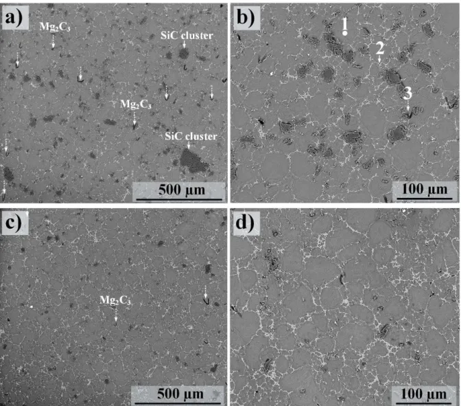
The second experiment- oxidized HCS 400 SiC particles: In this part of the study, alloy AZ91 was reinforced using the oxidized SiC particle type HCS 400. Figure 6 shows the as-cast microstructure of alloy AZ91-based MMC produced by HCS 400 using two fs values of 40 (Figs. 5a and b) and 60%
(Figs. 6c and d). An overall inspections showed that while the sub-micron SiC particles were distributed almost at everywhere including inter-dendritic regions and also in the interior of α-Mg grains in the MMC produced in the first experiment, the micro-sized SiC particles were mostly distributed in the inter-dendritic regions. SiC particulates and clusters were recognizable in SEM images. Clustering of SiC particles was much less pronounced when using HCS 400 compared to those containing SiC particle type HCS 59N (compare Figs. 5 and 6). Furthermore, SiC clustering was considerably minimized when fs was 40%; compare Figs. 6a and b with Figs. 6c and d. This was also
supported by the statistical analyses; see below. Grain size measurements showed that the use of particle type HCS 400 resulted in an average α-Mg grain size of ~ 23 and 21 µm for the fs values of 40
and 60%, respectively. Thus, a coarser grain structure in alloy AZ91D was formed with the same fraction of solids (60 %) when using particle type HCS 400 rather than HCS 59N; compare Figs. 6a
and b with Fig. 5c and d.
The SEM/EDX analyses of some of the microstructural features, i.e. points 1, 2 and 3, are provided in
Table 5. First of all, the number of intermetallic particle types could be identified by SEM/EDX was much less in the microstructure of composites produced in the second experiment compared to the first experiment (see also below). Secondly, the C content of the α-Mg grains in the microstructure of the alloy AZ91D reinforced by oxidized SiC particle type HCS 400 was significantly less in comparison with the MMCs produced by sub-micron sized particles. Thus, the C content reached 0.1-0.2 at.%; see for e.g. the chemical composition of point 1 in Table 5. It was found that the C content of the β phase
particles was also considerably decreased. Thus, β phase intermetallic particles exhibited a chemical composition very close to those formed on RC AZ91D; compare point 2 in Table 5 with point 5 in
Table 4. In addition to SiC particles and the main constituents, there was evidence for a type of Mg carbide, Mg2C3; see point 3 in Table 5. These carbide had a band-like morphology and were formed adjacent to the SiC particles. It was noted that the fraction of Mg2C3 increased with increasing fs. This
could be attributed to the more mechanical contact between the EEM and the SiC particles-containing melt during the slurry preparation. It may be noted that the formation of this carbide has also been reported in [41, 42].
1 2 3 4 5 6 7 8 9 10 11 12 13 14 15 16 17 18 19 20 21 22 23 24 25 26 27 28 29 30 31 32 33 34 35 36 37 38 39 40 41 42 43 44 45 46 47 48 49 50 51 52 53 54 55 56 57 58 59 60 61
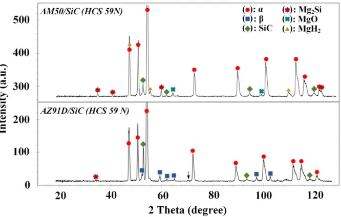
Figure 7 displays XRD patterns (a grazing incidence angle of 0.5º) of the RC AM50- and AZ91-based MMCs (HCS 59N). In both cases, relatively low intensity peaks corresponding to the β phase (Mg17Al12) were present in addition to the peaks corresponding to α-Mg. While the peaks related to β phase appeared with higher intensity and could be easily detected for the case of alloy AZ91D, they were hardly recognizable in the case of alloy AM50, which is in line with microstructural inspections (see Fig. 5). The XRD analysis showed no evidence of the AlMn phase, which is likely due to their low volume fraction. In both cases, strong peaks related to β-SiC were obvious. Peaks corresponding to Mg2Si intermetallic particles and MgO had a higher intensity for the alloy AM50 than AZ91D. Surprisingly, some peaks had characteristics very similar to Mg hydride (MgH2) in both MMCs. In all the XRD analyses performed, there was no indication of carbides in the XRD analyses using grazing incidence angle of 0.5º, which is consistent with the XRD patterns of SiC reinforced Mg-based MMCs. XRD patterns related to the MMCs (HCS 400) were not shown as the only phases that could be detected in those cases were the main phase, i.e. α-Mg, β phase and SiC particles.
TEM analysis was performed to further elucidate the effect of SiC additions on the formation of different phases. From qualitative SEM imaging (see the SEM images in Figs. 5 and 6), it was obvious that SiC particles tended to accumulate in the inter-dendritic regions. Figure 8 shows the STEM/EDX and STEM/EELS investigations performed on a FIB-prepared thin foil from an inter-dendritic region of Mg alloy AZ91D reinforced by SiC particle type HCS 59N. The darker area (point A in Fig. 8b
and Table 6) confirmed an Al content of 7.9 at.% indicating that the studied are was an inter-dendritic region. As seen, an island (the brighter are in Fig. 7a) was formed inside the inter-dendritic region. Point B in Table 6 shows the chemical compsotion of this island, where a compsition similar to point A was detected with some additions of Zn. It may be noted that C content increased from the darker area (point A) towards the brighter area (point B). The bright particles in Fig. 8a were SiC particles; see the chemical composition of C in Table 6. It is intresting to note that the C content of the SiC particles was less than their stochiometric composition. MgO and Mg2Si were also present close to SiC particles; see for e.g. points E and D in Figs. 8a and b and in Table 6. We also found another carbide consisted of Al and C, showing the chemical composition of Al4C3 (point E).
Figure 8c provides the time resolved and normalized EELS spectrum of the point designated by a
cross in Fig. 8a and b, adjacent to the SiC particle. The EELS analysis indicated the presence of MgH2 in the alloy’s microstructure which is in line with the detection of MgH2 by XRD (Fig. 7). Thus, at time 0s, two volume plasmon peaks of ∼10.6 and 14.55 eV were acquired corresponding to the Mg and α-MgH2, respectively [44, 45]. The relative intensity of the Mg peak increased as the exposure time to the electron beam increased, and after 630 s the peak corresponding to α-MgH2 had vanished and the phase was transformed into Mg due to the hydrogen loss from the hydride particle.
3.4. Materials quality; quantitative analyses
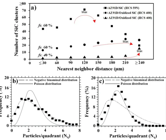
The uniformity of SiC particles and clusters as well as the fraction of casting defects were investigated in order to examine the MMCs’ quality. It should be noted that statistical analyses can provide broader, and thus more precise, descriptions of the MMC’s quality as they were determined from a relatively large area (4.2 mm2).The NND of SiC clusters larger than 40 µm, approximately equal to twice the size of the largest SiC particulates employed in this study, for alloy AZ91D reinforced by the two particle types and at the two different fs values are presented in Fig. 9a. From the statistical data, it
was clear that the number of clusters in the studied areas was in the order of HCS 59N (fs = 60%) >>
oxidized HCS 400 (fs = 60%) > oxidized HCS 400 (fs = 40%); see the x-axis in Fig. 9a. Thus, while
1 2 3 4 5 6 7 8 9 10 11 12 13 14 15 16 17 18 19 20 21 22 23 24 25 26 27 28 29 30 31 32 33 34 35 36 37 38 39 40 41 42 43 44 45 46 47 48 49 50 51 52 53 54 55 56 57 58 59 60 61
minimized when using the oxidized particle type HCS 400 with a lower fs, which was in accordance
with the qualitative assessments; see above.
In addition, the NND results indicated a large number SiC clusters were present at a lower distance interval (90-180 µm) and a small number clusters at the high distance intervals (more than 180 µm) in the microstructure of alloy AZ91D reinforced by the SiC particle type HCS 59N in comparison with those reinforced by the oxidized particle type HCS 400 at the two fs values of 40 and 60%. Moreover,
it was evident that at fs = 40% less clustering of the SiC particles occurred. Therefore, in that case SiC
clusters were more frequently formed at very high distance intervals (≥ 240 µm). It should be mentioned that the NND analysis of the RC alloy AM50 reinforced by HCS 59N (Figs. 5a and b) showed a somewhat similar pattern to the alloy AZ91D reinforced by the same particle type. The results obtained from the quadrat method (Fig. 9b and c) provided a general picture of the distribution of SiC particles owing the large area fraction of the investigation. Quadrat analysis was performed only on MMCs exhibiting much less SiC clustering and hence relatively better casting quality, i.e. Mg alloy AZ91D reinforced by oxidized particles type HCS 400 at the two fs values. The number of SiC
particles per quadrat was meaningfully different between MMCs produced by the two fractions of solid (Fig. 9a and b). Thus, the Mg alloy-based MMC produced using an fs of 40% followed the
negative binomial distribution, whereas the MMC produced by using an fs of 60% followed the
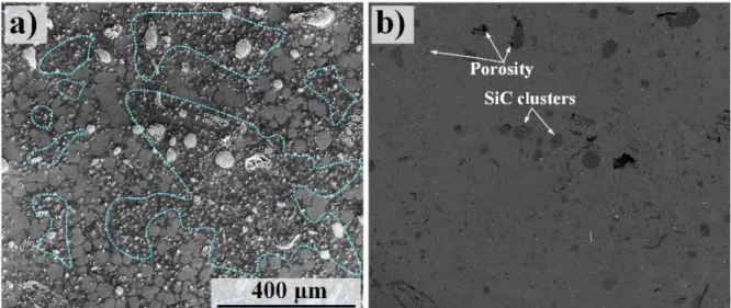
Poisson distribution type, confirming the uniform distribution of SiC particles in the latter case. The SEM micrographs shown above (Figs. 2, 5 and 6) were taken from the central regions of the castings. Inspecting areas close to the castings’ skins also resulted in some information on the materials’ microstructure and casting defects. Figure 10 shows an area ~ 1 mm from the cast skin in alloy AM50-based MMC. This micrographs shows the poorest part of the MMC, from a quality point of view. As expected [22], the grain structure became finer when approaching the cast skin. Frequently, regions exhibiting considerably fine α-Mg grins in the range 1-4 µm could be observed; see these regions in Fig. 10a. Similar regions could also be seen in the central regions of the castings, but to a lesser extent. Besides, particle-porosity association could be often observed, see the worst regions (from porosity point of view) in Fig. 9b. Such regions consisting of grain with extremely non-uniform size and SiC-associated defects were also present in the case of RC alloy AZ91D reinforced by the particle type HSC 59N, but could not be seen in the MMCs produced by the particle type HCS 400. To have a boarder image of the extent of casting defects, the fraction of casting defects were determined.
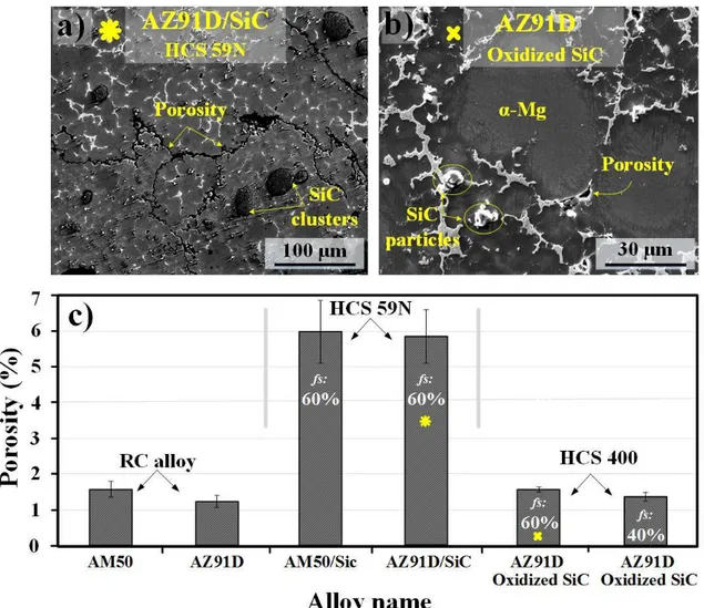
Figure 11 shows the morphology of pores and the quantitative assessments of the porosities in the materials produced by the RC technique. The SEM image in Fig. 11a shows relatively large connected casting pores in addition to the voluminous defects in the MMC produced by HCS 59N. In the case of the MMC (HCS 400), the pores were significantly smaller and were only formed in the inter-dendritic regions; see Fig. 11b. The data shown in Fig. 11c were obtained from an area of 4.2 mm2 and includes micro- and macro-pores. It was obvious that the casting porosity was much less in the MMC produced HCS 400 than HCS 59N, which is in line with microstructural observations described above. As seen, while the as-cast RC materials exhibited a pore fraction of 1-2%, the RC alloy materials reinforced by the particle type HCS 59N showed a ~ 3 times higher fraction of pores. The fraction of casting pores decreased to almost the same values as their host alloys for the alloys reinforced by the oxidized HCS 400. Besides, the fraction of pores in the MMCs reached its minimum value when fs was 40%. Thus, the trend in the extent of pores in the MMCs was similar to the
clustering tendency and the uniformity of SiC particles. 3.5. Hardness measurements
1 2 3 4 5 6 7 8 9 10 11 12 13 14 15 16 17 18 19 20 21 22 23 24 25 26 27 28 29 30 31 32 33 34 35 36 37 38 39 40 41 42 43 44 45 46 47 48 49 50 51 52 53 54 55 56 57 58 59 60 61
The variations in hardness of the alloys AM50, AZ91 and the MMCs are shown in Fig. 12. It was evident that the MMCs were harder than their host alloys. It should be mentioned that huge variation in the hardness values due to the presence of SiC clusters (especially in the case of MMCs produced by HCS 59N) were omitted from the data. The use of HCS 59N as reinforcements resulted in the maximum hardness, increasing the hardness from ~ 50 to 73 and 64 to 76 for alloy AM50 and AZ91D, respectively. HCS 400 gave rise to a lower hardness than HCS 59N but still higher than RC AM50 and AZ91D. Unlike the MMCs’ quality, decreasing the fs value did not result in a higher hardness but one
may consider the decrease in the scattering of the hardness results in the MMCs produced by HCS 400 using an fs value of 40% compared to the other MMCs.
4. Discussion
Based on the reasons presented in the Introduction, it is highly desirable to produce Mg-based MMC cast components with uniform reinforcement distribution and structural integrity. The RC method in combination with the RheoMetal process has already established itself as a promising casting technique enabling the production of high-quality and complex cast Mg alloys with enhanced service performances [22, 27, 28]. Thus, one expected to detect a relatively low fraction of casting pores, in the range of 1-2 % of the total examined area, in the RC AM50 and AZ91D alloys (see Figs. 2 and
11). In the case of RC alloys, the pores are frequently associated with the melt solidified in the inter-dendritic regions; see Fig. 2a. The commonly observed macro-porosities corresponding to large gas pores in the size range 100-500 µm, which are often formed in Mg alloys produced by the conventional HPDC method process, are not formed in the RC Mg alloys. This is a result of the fact that the RC process induces strong shearing forces on the slurry, causing the feed rate of the casting to increase, and thereby resulting relatively quick fill speeds at high pressure [22]. It is known that trapped gases and bubbles are formed during filling, while shrinkage defects occur when feed metal is not accessible to compensate for shrinkage as the metal solidifies [20-22]. Hence, less risk for trapped gas as well as shrinkage is expected in RC AM50, which is in accordance with the results obtained in this study. The low temperatures and high apparent viscosity of the semi-solid slurry also leads to less porosity in castings made using the RC technique.
Perhaps the most vital part of the MMC technology is the science of interface as interfacial reactions embodies many of the important aspects of MMCs properties. When discussing MMCs and interfacial reactions/properties, wetting characteristics of the ceramic particles becomes a crucial concept [1, 2]. Here, wettability is the ability of the molten metal to spread on a particle surface, and symbolizes the extent of intimate contact between the melt and ceramic particles [1]. Unluckily, the wettability of ceramic particles in molten Mg and Al and accordingly their alloys is poor, i.e. particles exhibit wetting angles considerably higher than 90º [15]. During the last two decades, various methods have been suggested to mitigate the wetting of ceramic particles by liquid metal, such as increasing metal liquid temperature, pre-treatment of particles (used in the second experiment in this study), and coating ceramic particles [46, 47].
The first experiment- non-oxidized HCS 59N SiC particles: It is, indeed, attractive to fabricate MMCs using nano-sized ceramic reinforcements as the addition of micron size ceramic particles, can reduce the ductility of the matrix although improves strength significantly [24]. Mg alloys reinforced by sub-micron sized ceramic particles are usually made through powder metallurgy, disintegrated melt deposition, friction stir processing and ultrasonic vibration; see for e.g. [48-50]. In this study we employed the RC process for fabricating Mg alloy AM50- and AZ91D-based MMCs using
1 2 3 4 5 6 7 8 9 10 11 12 13 14 15 16 17 18 19 20 21 22 23 24 25 26 27 28 29 30 31 32 33 34 35 36 37 38 39 40 41 42 43 44 45 46 47 48 49 50 51 52 53 54 55 56 57 58 59 60 61
micron sized SiC particle type HCS 59N. This part of the work was combined with various types of analytical techniques including TEM/EDX/EELS to shed light on the formation of all microstructural constituents that may form in SiC-reinforced Mg-based composites. As expected, non-oxidized SiC particles strongly tended to form clusters in the MMCs’ microstructures. It was quite challenging for us to achieve uniform dispersion of such small particles through casting as agglomeration and clustering frequently occurred during solidification due to high viscosity and poor wettability, the factors that are known to play a role in the soundness of nano-sized SiC-reinforced composites [51-54]. It may be noted that 10 vol.% of SiC, which was the case of this investigation, is a significant value of volume fraction for producing composites using nano-sized particles. Deng et al. [55], who attempted to produce Mg alloy AZ91 Mg matrix composites using sub-micron size SiC particulates using stir casting, only used 0.5-5 vol.% ceramic particles. Even though they employed many fewer fractions of SiC particles, they reported considerable amounts of SiC clusters in their MMCs’ microstructures.
Moreover, the MMCs fabricated by HCS 59N exhibited the maximum fraction of casting pores, both in the central and skin areas of castings. In addition to the pores associated with the melt solidifying in the inter-dendritic regions, SiC cluster-porosity association was also observed, see Fig. 10b. In a few cases, worm-like pores were seen in the MMCs’ microstructure, see Fig. 11a. In addition to the factors mentioned above, it is suggested that pores were mainly associated with the enormously large surface-to-volume ratio of SiC particles in the first experiment. Moreover, SiC particles in the first experiment were poorly degassed that can be attributed to their fresh (non-oxidized) surfaces. Casting pores in MMCs are normally generated from the solidification shrinkage, the entrapment of gases and hydrogen evolution [56, 57]. The entrapment of gases depends essentially on the processing parameters [56]. The hydrogen production is mainly the result of the reactions between the absorbed H2O and Mg melt. Some water vapor is usually absorbed on the surface of the added particles, even though the particles are pre-heated. Once entering the melt, the water vapor can react strongly with Mg, forming MgO and releasing H2. This also explains the formation of MgH2 at the SiC particle/alloy interface; see Fig. 8. It may be noted that the hydride phase, α-MgH2, has not previously been reported in the microstructure of Mg-based MMCs.
In the case of Mg alloy AM50, it was rather surprising that very little knowledge is available regarding the production of alloy AM50 reinforced by SiC particles, even when other ceramic particles are included. The only published work on the microstructure of alloy AM50-based MMC is the work done by Regev et al. [23]. They could successfully produce cast micron-sized SiC particle (in the range 4-30 µm) reinforced AM50 using a SSM process. However, they did not provide detailed information concerning probable intermetallic particles and carbides. An interesting observation was made when we noticed that the β phase intermetallic particles were only formed with a much smaller fraction compared to the RC AM50 (Figs. 5a and b). Instead, a phase containing Mg, Al, Si and C was formed in the inter-dendritic regions (Figs. 5a and b). Such interference of nano-sized SiC particles in the composition of β phase was also observed in the microstructure of alloy AZ91 reinforced by the same particle type. This indicates another difficulty in producing Mg alloys-based MMCs using nano-sized particles as both β phase particles and tiny SiC particles tend to settle in the inter-dendritic regions during solidification of Mg alloys-based MMCs.
In contrast to the composition of the β phase, the sub-micron sized SiC additions did not have an considerable effect on the composition of η phase intermetallic (Alx(Mn, Fe)y) particles in both alloys as they formed with approximately the same fraction as the RC alloys (compare the brightest particles in Figs. 2 and 5). This was also confirmed by image analysis techniques. However, the morphology of
1 2 3 4 5 6 7 8 9 10 11 12 13 14 15 16 17 18 19 20 21 22 23 24 25 26 27 28 29 30 31 32 33 34 35 36 37 38 39 40 41 42 43 44 45 46 47 48 49 50 51 52 53 54 55 56 57 58 59 60 61
η phase particles was somewhat different when comparing the microstructure of the MMCs and their monolithic counterparts. While η phase formed as semi-spherical particles in the RC materials, they appeared mostly as rod-like morphology in the MMCs (see for example Fig. 5a).
In the Mg-based MMCs, eutectic phases also form during the solidification process. These eutectic phases are able to wet the SiC particles and heterogeneously nucleate on the SiC substrate. The imperfections in the SiC particles, such as stacking faults, dislocations, and pits or grooves can act as favorable sites for heterogeneous nucleation [59]. In some cases, SiC particles near to the center of α-Mg grains were observed; see pint 4 in Fig. 5 and Table 4, which may suggest that they were nucleation sites for the grains. The potency of SiC particles acting as nucleation sites in Mg-based alloys are discussed in [59, 60]. Carbides were profoundly formed in the MMCs produced in the first experiment. It has been reported by several studies that carbides also play a role as grain refinements in the microstructure of Mg-based MMCs [61-64]. For example, Lu et al. [63], who examined the microstructure of an Mg-3%Al alloy reinforced by SiC particles, discussed the active role of the carbide Al4C3 in refining the grain structure of the MMC. Microstructural inspections (see for example
Fig. 10a) showed the formation of small α-Mg grains due to the large population of active nucleation
sites provided by the sub-micron sized SiC particles and carbides. Such microstructural configuration (with a reduced average grain size) might be beneficial from a mechanical properties standpoint, according to the Hall–Petch equation [2, 3], but may be detrimental from a corrosion standpoint. This stems from the fact that environmental degradation is an actual limiting factor for Mg-based alloys and that the atmospheric corrosion of Mg-based alloys is governed by the number of active cathodic sites and also available anodic sites [27, 28].
SEM/EDX, XRD and TEM/EDX/EELS revealed the formation of MgO, Mg2Si, MgH2, Al4C3, Al2MgC2 as the reaction products of SiC particles and the melts. A possible mechanism for the formation of the hydride phase was provided above. The presence of MgO and Mg2Si in the case of the alloys reinforced by non-oxidized particles was expected as the interaction of SiC particles with molten Mg that results in the formation of a mixture of Mg2Si and MgO intermetallic particles. The carbides are commonly seen in the Mg-based MMCs and are said (see for e.g. [15]) to form based on the following reactions;
4Al + 3SiC → Al4C3 + 3Si Equation (3)
2SiC +2Al+ 5Mg → 2Mg2Si + Al2MgC2 Equation (4)
Furthermore, α-Mg grains contained quite significant amount of C. This shows that the presence of C in the matrix grains can be attributed to instability of SiC particles in which C could easily diffused from the non-oxidized SiC particles towards α-Mg grains in the MMCs produced in the first experiment. Generally, microstructural examination revealed fewer types of intermetallics and carbides when using the oxidized SiC particle type HCS 400 than when using HCS 59N as a result of the particles’ stability provided by SiO2. This can also partially explain the slightly lower hardness values of the MMCs produced in the second experiment than those produced in the first one.
The second experiment; oxidized HCS 400 SiC particles In general, the MMCs produced by oxidized SiC particles (HCS 400) showed much better material quality. Thus, these MMCs produced through the RC technique exhibited a lower fraction of casting pores. Besides, only traces (in the range 0.1-0.3 at.%) of C in α-Mg grains could be detected owing the presence of SiO2 on the surface of particles, as proven through AES analysis (Fig. 4). The tendency for clustering and casting defects including the particle-associated pores and shrinkages was much less when oxidized HCS 400 using an fs of 60%
1 2 3 4 5 6 7 8 9 10 11 12 13 14 15 16 17 18 19 20 21 22 23 24 25 26 27 28 29 30 31 32 33 34 35 36 37 38 39 40 41 42 43 44 45 46 47 48 49 50 51 52 53 54 55 56 57 58 59 60 61
and homogeneity were minimized, or almost eliminated, when the fs decreased to 40%; see the SEM
images in Figs. 6c and d and the quantitative assessments in Figs. 9 and 11. Thus, increasing the fs
during the RC process did not give rise to a better wetting of SiC particles, and accordingly more dispersion on ceramic particles. This is rather surprising as one could have expected to obtain an opposite effect of fs on the quality of the MMCs as more mechanical stirring (by EEM), and
accordingly better wetting of particles, should occur at higher fs values. However, such increase in
mechanical contacts between the EEM and the melts seems to have a negative effect on quality of Mg-based MMCs. Nevertheless, the fraction of casting pores was slightly lower in the MMCs when the fs
was 40% (see Fig. 11). To find out the reason behind the effect of solid fraction on the MMCs’ quality future studies are planned by our research group.
The presence of Mg2C3 carbides in the MMC produced by oxidized SiC particles was notable. The formation of Mg2C3 in the case of composites reinforced by the oxidized particles is most likely linked to the reaction of SiO2 with molten Mg in some cases, and thus the melt became in contact with SiC particles to form carbides. The traces (in the order 0.1-0.2 at.%) of C content in the α-Mg grains also confirm the availability of C during solidification in this experiment.
5. Conclusion
We produced Mg alloy AM50- and AZ91D-based MMCs using the rheoprocessing, whereby the slurry was produced by the RhoMetal process. The following conclusions can be drawn from this study:
1. TEM/EDX/EELS showed the presence of different intermetallic particles and Al carbides in the inter-dendritic regions of the MMC produced by non-oxidized fine (sub-micron sized) SiC particles. The hydride MgH2, which was detected at the interface SiC/AZ91D, was suggested to be formed due to presence of water vapor on the surface of SiC particles, which resulted in the availability of H2 in inter-dendritic regions during the solidification.
2. Oxidation (at 1100ºC for 45 minutes) of SiC particles resulted in a much less contaminated α-Mg grains in the matrix of the MMCs owing to the formation of SiO2 on the SiC particles’ surfaces as well as less formation of undesired intermetallics and Al carbides in the microstructure of Mg alloys-based MMCs. The non-oxidized SiC particles gave rise in the presence of 1-2 at.% C content in the α-Mg grains, which was not the case for the MMC containing oxidized SiC particles.
3. The MMCs produced by macro-size oxidized particles exhibited low very low fraction of porosities, which was explained by desorption of adsorbed gases from SiC particle surfaces through the heat treatment procedure and significantly smaller number of specific surface areas as compared to the ones reinforced by nano-sized and non-oxidized SiC particles. 4. The quality of the MMCs was also examined using the NND and quadrat methods. It was
shown that the slurry fraction has a great impact on the quality of the MMCs produced through the RC technique. Thus, the MMC produced by 40% of solid in their slurry exhibited much better dispersion of SiC particles as well as much fewer casting defects than that produced by 60% solid fraction. To understand the reason behind this effect, however, future studies are needed.
1 2 3 4 5 6 7 8 9 10 11 12 13 14 15 16 17 18 19 20 21 22 23 24 25 26 27 28 29 30 31 32 33 34 35 36 37 38 39 40 41 42 43 44 45 46 47 48 49 50 51 52 53 54 55 56 57 58 59 60 61
Altogether, it was shown that the rheocasting technique in combination with the RheoMetal process exhibits promising potential for fabricating Mg-based MMCs with very low fraction of casting defects as well as excellent homogeneity of macro-sized ceramic particles, if the right set of process parameters are employed. From the foundry point of view, the results of this study are of importance in order to optimize the process parameters further and to understand the RC process and thereby develop the technique for producing high quality Mg-Al casting alloys-based MMCs on an industrial scale.
References
1. Chawla N, Cha KK. Metal Matrix Composites. Springer Science Business Media, New York; 2006.
2. Clyne TW, Withers PJ. An Introduction to Metal Matrix Composites. Cambridge University Press, UK; 1993.
3. Avedesian M, Baker H. Magnesium and Magnesium Alloys. ASM Materials Park; 1999. 4. Hassan SF, Gupta M. Development of high strength magnesium based composites using
elemental nickel particulates as reinforcement. J Mater Sci 2007;37:2467-2474.
5. Lu L, Thong KK, Gupta M. Mg-based composite reinforced by Mg2Si. Compos Sci Technol 2003;63:627-632.
6. Zhang X, Zhang Q, Hu H. Tensile behaviour and microstructure of magnesium AM60-based hybrid composite containing Al2O3 fibres and particles. Mater Sci Eng A 2014;607:269-276. 7. Lu D, Jiang Y, Zhou R. Wear performance of nano-Al2O3 particles and CNTs reinforced
magnesium matrix composites by friction stir processing. Wear 2013;305:286-290.
8. Paramsothy M, Tan XH, Chan J, Kwok R, Gupta M. Al2O3 nanoparticle addition to concentrated magnesium alloy AZ81: Enhanced ductility. J Alloy Comp 2012;545:12-18. 9. Ferkel H, Mordike BL. Magnesium strengthened by SiC nanoparticles. Mater Sci Eng A
2001;298:193-199.
10. Gui M, Li P, Han J. Fabrication and characterization of cast magnesium matrix composites by vacuum stir casting process. J Mater Eng Perform 2003;12:128-134.
11. Degischer HP, Schulz PA, Lacom W. Properties of Continuous Fibre Reinforced Al and Mg-Matrix Composites Produced by Gas Pressure Infiltration. Key Eng Mater 1996;127-131:99-110.
12. Tun KS, Gupta M. Improving mechanical properties of magnesium using nano-yttria reinforcement and microwave assisted powder metallurgy method. Compos Sci Technol 2007;67:2657-2664.
1 2 3 4 5 6 7 8 9 10 11 12 13 14 15 16 17 18 19 20 21 22 23 24 25 26 27 28 29 30 31 32 33 34 35 36 37 38 39 40 41 42 43 44 45 46 47 48 49 50 51 52 53 54 55 56 57 58 59 60 61
13. Liu YB, Lim SC, Lu L, Lai MO. Recent development in the fabrication of metal matrix-particulate composites using powder metallurgy techniques. J Mater Sci 1994;29:1999-2007. 14. Hu H. Squeeze casting of magnesium alloys and their composites. J Mater Sci
1998;33:1579-1589.
15. Ye HZ, Liu XY. Review of recent studies in magnesium matrix composites. J Mater Sci 2004;39:6153-6171.
16. Loh NH, Tor SB, Khor KA. Production of metal matrix composite part by powder injection molding. J Mater Proc Technol 2001;108:398-407.
17. Wang HY, Jiang QC, Li XL, Wang JG. In situ synthesis of TiC/Mg composites in molten magnesium. Scr Mater 2003;48:1349-1354.
18. Siedersleben M. Vakuum-Druckguss von Magnesiumlegierungen fur hochbelastete Bauteile, Magnesium Eigenschaften, Wiley-VCH, Weinheim; 2000.
19. Emley EF. Principals of magnesium technology, Pergamon Press, Oxford; 1966.
20. Ostklint M, Wessén M, Jarfors AEW. Microstructure and material soundness in liquid and rheocast AM50 and effect of section thickness. Int J Cast Metal Res 2014;27:235-241.
21. Ostklint M, Wessén M, Jarfors AEW. Microstructure and material soundness in liquid and rheocast AZ91: effect of section thickness. Int J Cast Metal Res 2015;28:65-71.
22. Esmaily M, Shahabi-Navid M, Mortazavi N, Svensson JE, Halvarsson M, Wessén M, Jarfors AEW, Johansson LG. Microstructural characterization of the Mg-Al alloy AM50 produced by a newly developed rheo-casting process. Mater Charac 2014;95:20-64.
23. Regev M, Rosenson H, Koren Z. Microstructure study of particle reinforced AZ91D and AM50 magnesium alloy semisolid casting. Mater Sci Technol 2007;23:1485-1491.
24. Kleiner S, Beffort O, Wahlen A, Uggowitzer PJ. Microstructure and mechanical properties of squeeze cast and semi-solid cast Mg-Al alloys. J Light Metal 2002;2:277-280.
25. Kaufmann H, Potzinger R, Uggowitzer PJ. The relationship between processing and properties of new rheocast AZ91 and AZ71 magnesium alloys. Light Metal Age 2001:56-61.
26. Poddar P, Mukherjee S, Sahoo KL. The microstructure and mechanical properties of sic reinforced magnesium based composites by Rheocasting process. J Mater Eng Perf 2009;18:849-855.
27. Esmaily M, Mortazavi N, Shahabi-Navid M, Svensson JE, Halvarsson M, Nyborg L, Wessén M, Jarfors AEW, Johansson LG. Effect of Rheocasting on corrosion of AM50 Mg alloy. J Electrochem Soc 2015;162:C85-C95.
28. Esmaily M, Mortazavi N, Svensson JE, Halvarsson M, Blücher DB, Jarfors AEW, Wessén M, Johansson LG. Atmospheric corrosion of mg alloy AZ91d fabricated by a semi-solid casting technique: the influence of microstructure. J Electrochem Soc 2015;162:C311-C321.
29. Walton WH. Feret‘s statistical diameter as a measure of particle size. Nature 1948;330:329-330.
30. Pyrz R. Quantitative description of the microstructure of composites. Part I: Morphology of unidirectional composite systems. Compos Sci Technol 1994;50:197-208.
31. Tzamtzis S, Barekar NS, Babu H, Patel J, Dhindaw BK, Fan Z. Processing of advanced Al/SiC particulate metal matrix composites under intensive shearing - A novel Rheo-process. Compos Part A: Appl Sci Manuf 2009;40:144-151.
1 2 3 4 5 6 7 8 9 10 11 12 13 14 15 16 17 18 19 20 21 22 23 24 25 26 27 28 29 30 31 32 33 34 35 36 37 38 39 40 41 42 43 44 45 46 47 48 49 50 51 52 53 54 55 56 57 58 59 60 61
33. Bankoti AKS, Mondal AK, Kumar S, Ray BC. Individual and combined additions of calcium and antimony on microstructure and mechanical properties of squeeze-cast AZ91D magnesium alloy. Mater Sci Eng A 2015;626:186-194.
34. Luo S, Chen Q, Zhao Z. Effects of processing parameters on the microstructure of ECAE-formed AZ91D magnesium alloy in the semi-solid state. J Alloy Comp 2009;477:602-607. 35. Esmaily M, Shahabi-Navid M, Svensson JE, Halvarsson M, Nyborg L, Cao Y, Johansson LG.
Influence of temperature on the atmospheric corrosion of the Mg-Al alloy AM50. Corros Sci 2015;90,420-433.
36. Ma Y, Zhang J, Yang M, J. Research on microstructure and alloy phases of AM50 magnesium alloy. J Alloy Comp 2009;470:515-521.
37. Mathaudhu SN, Sillekens WH, Neelameggham NR, Hort N, editors. TMS Magnesium technology, Orlando, FL, USA; 2012.
38. Agarwala V, Dixit D. Fabrication of Aluminium base composite by foundry technique. Trans Japan Inst Met 1981;22:521-526.
39. Harris RCA. Oxidation of 6H-alpha Silicon Carbide Platelets. J Am Ceram Soc 1975;58:7-9. 7-9
40. Fukuda H, Kondoh K, Umeda J, Fugetsu B. Fabrication of magnesium based composites reinforced with carbon nanotubes having superior mechanical properties. Mater Chem Phys 2011;127:451-458.
41. Feldhoff A, Pippel E, Woltersdorf J. Carbon-fibre reinforced magnesium alloys: nanostructure and chemistry of interlayers and their effect on mechanical properties. J Micros 1999;196:185-193.
42. Russell-Stevens M, Todd R, Papakyriacou M. Microstructural analysis of a carbon fiber reinforced AZ91D magnesium alloy composite. Surf Interface Anal 2005;37:336-342.
43. Chua BW, Lu L, Lai MO. Influence of SiC particles on mechanical properties of Mg based composite. Compos Struct 1999;47;595-601.
44. Jeon KJ, Moon HR, Ruminski AM, Jiang B, Kisielowski C, Bardhan R, Urban JJ. Air-stable magnesium nanocomposites provide rapid and high-capacity hydrogen storage without using heavy-metal catalysts. Nature Mater 2011;10:286-290.
45. Danaie M, Tao SX, Kalisvaart P, Mitlin D. Analysis of deformation twins and the partially dehydrogenated microstructure in nanocrystalline magnesium hydride (MgH2) powder. Acta Mater 2010;58:3162-3172.
46. Rohatgi PK, Asthana R, Das S. Solidification, structures, and properties of cast metal-ceramic particle composites. Inter Metal Rev 1986;31:115-139.
47. Hashim J, Looney L, Hashmi MSJ. The wettability of SiC particles by molten aluminium alloy. J Mater Process Technol 2001;119:324-328.
48. Faraji G, Dastani O, Akbari Mousavi AA. Effect of Process parameters on microstructure and micro-hardness of AZ91/Al2O3 surface composite produced by FSP. J Mater Eng Perform 2011;20:1583-1590.
49. Nguyen QB, Gupta M. Increasing significantly the failure strain and work of fracture of solidification processed AZ31B using nano-Al2O3 particulates. J Alloy Comp 2008;459:244-250.
50. Shen MJ, Wang XJ, Li CD, Zhang MF, Hu XS, Zheng MY, Wu K. Effect of bimodal size SiC particulates on microstructure and mechanical properties of AZ31B magnesium matrix composites. Mater Des 2013;52:1011-1017.
1 2 3 4 5 6 7 8 9 10 11 12 13 14 15 16 17 18 19 20 21 22 23 24 25 26 27 28 29 30 31 32 33 34 35 36 37 38 39 40 41 42 43 44 45 46 47 48 49 50 51 52 53 54 55 56 57 58 59 60 61
51. Deng K, Shi J, Wang C, Wang X, Wu Y, Nie K, Wu K. Microstructure and strengthening mechanism of bimodal size particle reinforced magnesium matrix composite. Compos Part A: Appl Sci Manuf 2012;43:1280-128.
52. Oh S, Cornie J, Russell K. Wetting of ceramic particulates with liquid aluminum alloys: Part II. Study of wettability. Metall Trans 1989;20A:533-541.
53. Eustathopoulos N, Nicholas MG, Drevet B. Wettability at High Temperature. Elsevier, Kidlington; 1999.
54. Bahraini M, Minghetti T, Zoellig M, Schubert J, Berroth K, Schelle C, Graule T, Kuebler J. Activated pressureless infiltration of metal-matrix composites with graded activator content. Compos Part A: Appl Sci Manuf 2009;40:1566-1572.
55. Deng KK, Wu K, Wu YW, Nie KB, Zheng MY. Effect of submicron size SiC particulates on microstructure and mechanical properties of AZ91 magnesium matrix composites. J Alloy Comp 2010;504:542-547.
56. Bindumadhavan PN, Chia TK, Chandrasekaran M, Wah HK, Lam LN, Prabhakar O. Effect of particle-porosity clusters on tribological behavior of cast aluminium alloy A356–SiCp metal matrix composites. Mater Sci Eng A 2001;315:217-226.
57. Gupta M, Sharon NML. Magnesium, Magnesium Alloys, and Magnesium Composites. John Wiley & Sons Inc.; 2011.
58. Lu L, Dahle AK, StJohn DH. Grain refinement efficiency and mechanism of aluminium carbide in Mg-Al alloys. Scr Mater 2005;53:517-522.
59. Günther R, Hartig C, Bormann R. Grain refinement of AZ31 by (SiC)P: Theoretical calculation and experiment. Acta Mater 2006;54:5591-5597.
60. Cai Y, Taplin D, Tan MJ, Zhou W. Nucleation phenomenon in sic particulate Reinforced magnesium composite. Scr Mater 1999;41:967-971.
61. Kim YM, Yim CD, You BS. Grain refining mechanism in Mg-Al base alloys with carbon addition. Scr Mater 2007;57:691-694.
62. Lu L, Dahle AK, StJohn DH. Heterogeneous nucleation of Mg-Al alloys. Scr Mater 2006;54:2197-2201.
63. Qian M, Cao P. Discussions on grain refinement of magnesium alloys by carbon inoculation. Scr Mater 2005;52:415-419.
64. Tamura Y, Kono N, Motegi T, Sato E. Grain refinement of cast Mg-Al alloys. J Japan Inst Light Metal 1998;48:395-399.
1 2 3 4 5 6 7 8 9 10 11 12 13 14 15 16 17 18 19 20 21 22 23 24 25 26 27 28 29 30 31 32 33 34 35 36 37 38 39 40 41 42 43 44 45 46 47 48 49 50 51 52 53 54 55 56 57 58 59 60 61
1 2 3 4 5 6 7 8 9 10 11 12 13 14 15 16 17 18 19 20 21 22 23 24 25 26 27 28 29 30 31 32 33 34 35 36 37 38 39 40 41 42 43 44 45 46 47 48 49 50 51 52 53 54 55 56 57 58 59 60 61
Fig.1. Schematic of the RC process used for preparing the RC alloys and Mg alloys-MMCs; step1:
melt preparation, step 2: EEM preparation, step 3: rheo-processing (slurry preparation) (SiC particulates were added into the melt at this stage for fabricating the MMCs), step 4: pouring the slurry into the shot sleeve, and step 5: high pressure casting unit. Note: Step 1 and 3 were performed in the same furnace but with some time intervals.
1 2 3 4 5 6 7 8 9 10 11 12 13 14 15 16 17 18 19 20 21 22 23 24 25 26 27 28 29 30 31 32 33 34 35 36 37 38 39 40 41 42 43 44 45 46 47 48 49 50 51 52 53 54 55 56 57 58 59 60 61
Fig. 2. SEM micrographs showing typical microstructures of alloys; (a) and (b) AM50, (c) and (d)
1 2 3 4 5 6 7 8 9 10 11 12 13 14 15 16 17 18 19 20 21 22 23 24 25 26 27 28 29 30 31 32 33 34 35 36 37 38 39 40 41 42 43 44 45 46 47 48 49 50 51 52 53 54 55 56 57 58 59 60 61
Fig. 3. SEM micrographs and particles size distribution of SiC particles used to produce the