Evaluation of Real-Time databases
in a control-system setting
Marcos José Coronado Romero
Mimer Information Technology AB
School of Innovation, Design and Engineering
Mälardalen University
September 10
th, 2010
Mimer Information Technology AB
Uppsala, Sweden
Supervisor: Dag Nyström
Mälardalen University
Västerås, Sweden
Supervisor: Andreas Hjertström
andreas.hjertstrom@mdh.se
Abstract
This thesis is related to the knowledge area of real-time systems and real-time databases.
The increasing complexity of the systems, specifically the embedded systems, and the need of store and share the information they use leads to the need of new technologies. For this reason a need of real-time database management system has emerged to satisfy the new requirements. Several commercial database systems claim to be real-time, but this technology is not consolidated enough.
The thesis will perform an evaluation of those databases mainly in predictability terms since predictability is necessary for the correct execution of hard real-time systems. In order to complete the evaluation, a real-time database application has been implemented. This application implements two commercial databases, namely Mimer and eXtremeDB, and a monitor application which is responsible for displaying all the relevant database behavior‟s information at runtime. A comparative studying of both databases has been carried out in order to determine how predictable these databases are. Parameters such as response time, CPU time consumption, etc has been studied. Finally, it can be concluded that both databases are predictable to a certain level. On one hand Mimer has an estimation of the worst case response time around 12 µs and CPU overload of 36%, and the fluctuation along the transactions is nearly negligible. On the other hand, eXtreme has an estimation of the worst-case response time around 18 µs and CPU overload of 41%, and the fluctuation along the transactions are rather bigger than the Mimer‟s. However, it can be concluded that both databases provide real-time transactions and, thus, they are able to be implemented in real-time systems.
Acknowledgements
First of all, I would like to dedicate this thesis to my parents Marcos and María del Rosario, and my sister Isabel because they always have supported me and also because they have given me the opportunity of coming to a new country, knowing a new culture and finishing my degree in a leading research university as Mälardalen Högskola.
In addition, I want to be grateful to my examinator Dag Nyström and my supervisor Andreas Hjertström for their help, support and encourage when I have had problems throughout the thesis process; apart from all the knowledge I have got from them. On the other hand, I want to be grateful to Chris Mureen from McObject for their tireless responding to every doubt I have sent him during the thesis process.
___________________________
En primer lugar quisiera dedicar este trabajo a mis padres Marcos y María del Rosario, y de mi hermana Isabel por el apoyo que me han ofrecido siempre y también por haberme dado la oportunidad y el respaldo para venir a un nuevo país a conocer una nueva cultura y a poder completar mis estudios en una universidad tan puntera e innovadora como es Mälardalen Högskola.
Además quiero agradecer a mi examinador Dag Nyström y mi supervisor Andreas Hjertström toda la ayuda, el apoyo y el ánimo que me han dado cuando he tenido problemas a lo largo de todo este tiempo; además de todo lo que he aprendido con ellos. También quiero agradecer la ayuda recibida de Chris Mureen por parte de McObject, que ha respondido incansablemente a todos las dudas y consultas que le he hecho durante el desarrollo del proyecto.
___________________________
Först och främst tillägnar jag denna avhandling till mina föräldrar Marcos och María del Rosario, och till min syster Isabel eftersom dom alltid stöttat mig och också därför att dom har gett mig möjligheten att få åka till ett nytt land, lära känna en ny
Vidare är jag är jag tacksam för allt stöd, all support och all uppmuntran jag fått från min examinator Dag Nyström och min handledare Andreas Hjertström, särskilt under dom perioder när jag hade problem att genomföra detta project. Tack för att ni delat med er av er kunskap. Slutligen skulle jag vilja tacka Chris Mureen från McObject för hans tålmodiga svarande på alla mina undringar som jag skickat till dem under detta projekt.
CONTENT
Chapter 1. Introduction ... 1 1.1 Problem Description ... 2 1.2 Thesis contribution ... 2 1.3 Outline ... 2 Chapter 2. Background ... 5 2.1 Real-Time systems ... 52.1.1 Tasks: Definition and types... 6
2.1.2 Hard real-time and Soft real-time ... 6
2.1.3 Real-Time Operating System ... 7
2.2 Databases ... 7 2.2.1 Transaction Characteristics ... 9 2.2.2 Concurrent Transactions ... 9 2.2.3 Concurrency Control ... 11 2.3 Real-Time Databases ... 12 2.3.1 Transaction characteristics ... 12 2.3.2 Performance requirements ... 13 2.3.3 Concurrency Control ... 13
2.3.4 Client/server vs. embedded library architecture ... 16
Chapter 3. Related Work ... 19
3.1 Mimer SQL Real-Time Edition ... 19
3.1.1 Performance ... 20
3.1.2 Concurrency control... 20
3.1.3 Architecture ... 21
3.2 eXtreme DB Standard Edition ... 22
3.2.1 Performance ... 22
3.2.2 Concurrency control... 23
3.2.3 Architecture ... 24
3.3 Oracle Times Ten In-Memory ... 24
Chapter 4. The benchmark application ... 29
4.1 System overall ... 29
4.2 The real-time application ... 31
4.3 The real-time system ... 31
4.4 The Graphical User Interface ... 33
Chapter 5. The benchmark setup ... 39
5.1.1 Test case 1 ... 41 5.1.2 Test case 2 ... 41 5.1.3 Test case 3 ... 41 5.1.4 Test case 4 ... 42 5.1.5 Test case 5 ... 42 5.2 Platform configuration ... 42 5.2.1 Limitations ... 43
Chapter 6. Benchmark results ... 45
6.1 Worst-case response time analysis ... 45
6.1.1 No database worst-case response time ... 46
6.1.2 eXtremeDB worst-case response time ... 47
6.1.3 Mimer worst-case response time ... 48
6.1.4 Worst-case response time summary ... 49
6.2 Average response time ... 50
6.2.1 Task A average response time ... 50
6.2.2 Task B average response time ... 51
6.2.3 Task C average response time ... 52
6.3 CPU time consumption ... 53
Chapter 7. Conclusion ... 55
Chapter 8. Future work ... 57
Chapter 9. References ... 59
Appendix A. Raw data from the benchmark ... 61
Test Case 1 ... 61
Mimer ... 69 No-database ... 71 Test Case 3 ... 73 eXtremeDB ... 73 Mimer ... 75 No-database ... 77 Test Case 4 ... 79 eXtremeDB ... 79 Mimer ... 81 No-database ... 83 Test Case 5 ... 85 eXtremeDB ... 85 Mimer ... 87 No-database ... 89
Table index
Table 1. Comparing Client/server vs. Embedded library... 18
Table 2. Mimer SQL Real-Time Performance [19] ... 20
Table 3. Test case input description ... 39
Table 4. Test case output description ... 40
Table 5. Test case 1 description ... 41
Table 6. Test Case 2 description ... 41
Table 7. Test Case 3 description ... 41
Table 8. Test Case 4 description ... 42
Table 9. Test Case 5 description ... 42
Table 10. Platform characteristics ... 43
Figure index
Figure 1. Three levels architecture of database manage system ... 8
Figure 2. Transactions flow ... 9
Figure 3. Example of conflict during concurrent transactions ... 10
Figure 4. Three phases of transactions under OCC [7] ... 11
Figure 5. Client/server architecture [27] ... 16
Figure 6. Embedded library architecture [27] ... 17
Figure 7. Response time for hard transactions using database pointers [14] ... 21
Figure 8. Response time for hard transactions using 2PL-HP [14]... 21
Figure 9. Overview of Mimer SQL Real-Time Edition architecture [27] ... 22
Figure 10. Times Ten overview design [11] ... 25
Figure 11. Read commited isolation scheme [11] ... 26
Figure 12. Serializable isolation [11] ... 27
Figure 13. Times Ten architecture [11]. ... 27
Figure 14. System overall ... 30
Figure 15. Tasks schema ... 33
Figure 16. Application initial screen ... 34
Figure 17. Real-Time Monitor tab ... 35
Figure 18. System monitor tab ... 36
Figure 19. Statics tab ... 37
Figure 20. System log tab ... 38
Figure 21. No database response time. ... 46
Figure 22. No-database response time disregarding the operating system interruptions ... 46
Figure 23. eXtremeDB response time disregarding the operating system interruptions ... 47
Figure 24. eXtremeDB's worst-case response time estimation... 48
Figure 25. Mimer response time disregarding the operating system interruptions ... 48
Figure 26. Mimer's worst-case response time estimation ... 49
Figure 27. Average response time - Task A ... 51
Figure 28. Average response time - Task B ... 52
Figure 29. Average response time - Task C ... 53
CHAPTER 1.
INTRODUCTION
Day by day, millions of industrial systems are being developed and released in order to meet the needs of the society. Those systems process huge amounts of information, for that reason databases are becoming increasingly important. In addition, real-time systems are growing and becoming more and more important. Most real-time systems are embedded systems. An embedded system is designed to perform one or more specific tasks and usually with limited resources and real-time constraints. Traditional databases are not good enough and new databases have to be designed in order to satisfy real-time constraints (response time, jitter, memory consumption, predictability, small footprint, etc).
Those constraints are not trivial to satisfy but, on the other hand, they are necessary to keep the correct performance of these systems. Specifically, predictability in real-time systems is one of the most important features to achieve. Furthermore, this feature is even more difficult to fulfill when databases are part of the system because it introduces factors of unpredictability such as I/O accesses, context switches between the different processes, concurrency issues, etc. In order to provide databases with real-time performance, designers and engineers have developed new concurrency control algorithms and memory techniques. Despite the improvements, predictability in real-time databases is still hard to achieve; some companies like Oracle [11], McObject [10] and Mimer [24] claim that their databases support hard real-time transactions. Actually, those databases are far faster than traditional databases but are they 100 per cent reliable in predictability terms? Do they really support real-time as they claim?
The aim of this thesis is to evaluate the behaviour and performance of commercial real-time databases that are designed for embedded real-time systems. The evaluation is performed using different workloads in order to evaluate their predictability and fitting to real-time systems. In order to do the evaluation, a real-time application using those databases has been developed. Properties as number of tasks, period of the tasks or
will display the system performance at runtime. Parameters as response time, jitter, missed deadlines, CPU time consumption, etc, will be displayed.
1.1 PROBLEM DESCRIPTION
a) Are the real-time commercial databases 100% reliable for real-time systems as they claim?
b) Which parameters are needed to evaluate the real-time databases? c) How to carry out an evaluation of those databases?
1.2 THESIS CONTRIBUTION
The contributions of this thesis are:
a) Designing a new benchmark application able to monitor the behaviour of real-time databases.
b) Evaluating the real-time performance of two commercial real-time databases.
c) Comparing the two databases and discuss their real-time properties and their claim to be real-time.
1.3 OUTLINE
Chapter 3: Description of three commercial real-time databases: Mimer SQL Real-Time Edition, eXtremeDB 4.0 Standard version, Oracle Times Ten In Memory Database.
Chapter 4: Description of the design and architecture of the benchmark application built in this thesis which will be used to test the real-time databases described in the chapter before.
Chapter 5: Description of the test bench used to evaluate the databases. Chapter 6: The results got from the test will be described and analyzed.
Chapter 7: Discussion about the future work which can be included in this thesis. Appendix A: Graphs from the benchmark.
CHAPTER 2.
BACKGROUND
In order to get familiarized with the basic concepts related with our problem, we are going to explain the basic ideas about real-time systems going through their definition, different types of real-time systems and real-time operating-systems; databases, focusing mainly on the transactions characteristics and the concurrency control and finally we will talk about real-time databases, focusing on how the features described for traditional databases and real-time databases are achieved.
2.1 REAL-TIME SYSTEMS
In the last two decades real-time systems have been growing and growing. Nowadays, real-time systems appear in embedded systems such as industrial systems, electronic devices, etc. Embedded systems are designed to perform one or more specific task; those systems usually have limitations as small memory.
A Real-Time system [1] is a system which gets information from the environment (sensors, other systems, etc.) and, based on that information, the system gives a response within a certain time frame. Thus, a real-time system‟s correctness depends does not only on the logical structure of the algorithms and the correctness of the results, it also depends on the time when the result is delivered.
There are several characteristics that define real-time systems such as [1]:
a) Predictability: It is the main characteristic and every real-time system must fulfil that. Predictability doesn‟t mean fast, it means that for every activity, predictability in the system must be maintained.
b) Peak load: Real-time systems must be predictable even when the system workload reaches the maximum.
2.1.1 TASKS:DEFINITION AND TYPES.
A task is [1] a fragment of code that compounds a sequential program which performs an activity in order to fulfil the system requisites.
a) Periodic: A periodic task is the type of task which is executed in regular intervals [1].
b) Aperiodic: An aperiodic task is the type of task which is executed irregularly [1].
c) Sporadic: A sporadic task is the type of task that can arrive at the system at arbitrary points in time. However, it has a defined minimum inter-arrival time between two subsequent invocations.
2.1.2 HARD REAL-TIME AND SOFT REAL-TIME
Depending on the functionality of each system we can have “hard” or “soft” systems but usually real-time systems support both [1].
a) Soft real-time: It means that the system can miss their deadlines but performance will be decreased. For example, in a real-time video streaming, if the system miss the deadlines the quality of the video will be decreased, but the video will keep working [1].
b) Hard real-time: In contrast to soft systems, hard real-time systems must not miss their deadlines. If a deadline is missed the system will fail and it may lead catastrophic consequences. For example, in an airplane control system, while landing, if the system misses any deadline and the height sensor is not
2.1.3 REAL-TIME OPERATING SYSTEM
A real-time operating-system (RTOS) is [1] a platform that offers the programmers several advantages to develop real-time systems. RTOS are designed to meet the real-time systems requisites. Thus, instead of throughput, predictability is the main goal of real-time operative systems. There are two types of RTOS:
a) Event Triggered: In this kind of RTOS the tasks are activated for external signals, for example signals received from sensors. Event triggered systems usually are simple and works properly in systems with enough resources and in systems with low workload [1].
b) Time Triggered: In Time triggered RTOS tasks are activated regularly according to the clock, i.e. all the tasks are activated in a predetermined point in time [1].
Finally, the actual real-time operating-systems support event triggered and time triggered together in order to improve the flexibility and performance.
2.2 DATABASES
Traditional database systems, hereafter referred to simply as databases, have been designed to manage persistent data, i.e. data is stored in the hard disk until either updated or removed. Data in a database is manipulated using operations (or queries), the most used operations in databases are: INSERT, UPDATE, SELECT or DELETE. Operations can either be executed one by one, or be grouped together in atomic transactions. In order to keep the consistency within the database, transactions must fulfil the „serializability criterion‟ which states that there must be an equivalence in the outcome, the database state, data values, to a serial schedule (i.e., sequential execution with no transaction overlap in time) with the same transactions [22].
To access the database a so called database management system (DBMS) is used. A DBMS is a software application that controls the storage of the data. The creation, use and maintenance of the database are typical tasks related with a DBMS.
Database Management System usually consists of three levels [23] (see Figure 1): a) The internal level, or physical level, deals with the physical storage of the data
onto a media. Its interface to the conceptual level abstracts all such information away. So, the physical level is responsible of abstract the other levels from how the data is stored, i.e. the physical level deals with partitions, CPUs, tablespaces, etc.
b) The conceptual level represents the logical structure of the entire database. This level handles the relationships among the data and a complete view of the data requirements of the organization independent of any storage consideration.
c) The external level contains interfaces to users, uniforming transactions before they are sent to the conceptual level. This level provides a different view of the database for each group of users; this is a powerful security mechanism since the users does not have knowing of the existence of other information in the database, they only know about their view.
The main goal of databases is to achieve the lowest average response time and a good throughput.
2.2.1 TRANSACTION CHARACTERISTICS
A database transaction is a logical, and atomic, unit of work made up of one or more operations against the data in one or more databases. The effects of the transaction can be either committed (applied to the database) or rolled back (undone from the database) (see Figure 2).
The properties of database transactions are summed up with the acronym ACID [28]:
a) Atomicity: All of the tasks of a database transaction must be completed; if any of the tasks is incomplete due to any possible reasons, the database transaction must be aborted, and the database state must be the same as before the transaction was started.
b) Consistency: The database must be in a consistent state before and after the database transaction. It means that a database transaction must not break the database integrity constraints. Integrity constrains are used to ensure the accuracy and consistency of data. An example of integrity constraints could be that every table must have a PRIMARY KEY.
c) Isolation: Data used during the execution of a database transaction must not be used by another database transaction until the execution is completed.
d) Durability: All the database modifications of a transaction will be made permanent even if a system failure occurs after the transaction has been completed. TIME B BEEGGIINN T TRRAANNSSAACCTTIIOONN QQUUEERRIIEESS C COOMMMMIITT// R ROOLLLLBBAACCKK
Concurrent transactions appear in database systems where two or more transactions are running at the same time, i.e. the “start” of one transaction takes place between the “start” and the “commit” of the other. When concurrent transactions happen, transaction conflicts could appear. Let‟s see an example of a transaction conflict (see Figure 3).
Suppose two customers who want to deposit money into the same account. Customer 1 deposit 1.000.000 €, customer 2 deposit 2.000.000 €, the previous account balance is 500.000 €. If the transactions executes in the following order:
Customer 1 Database Customer 2
500.000 € Read balance Balance 500.000 € 500.000 € 500.000 € Read Balance Balance 500.000 Add 1.000.000 € Balance 1.500.000 € 500.000 €
Write balance in the DB 1.500.000 €
1.500.000 € Add 2.000.000 €
Balance 2.500.000
2.500.000 € Write balance in the DB
Figure 3. Example of conflict during concurrent transactions
2.2.3 CONCURRENCY CONTROL
In databases systems where several transactions are carried out in a concurrent way, it is necessary to have some mechanism to ensure that the ACID properties are being fulfilled. This mechanism is called Concurrency Control (CC) [7] [14] [16]. The main goal of the concurrency control is to ensure that the transactions are safely executed concurrently without violating the database integrity.
There are mainly two mechanisms to achieve the concurrency control [7]: the Pessimistic Concurrency Control (PCC) and the Optimistic Concurrency Control (OCC).
a) Pessimistic Concurrency Control: PCC uses locks to block the transactions if the transaction may lead to a conflicting situation, i.e. violation of the ACID rules; the transactions are blocked until the possibility of violation disappears. This mechanism is used to prevent that several transactions access the same data at the same time [7].
b) Optimistic Concurrency Control: OCC do not block the transactions execution and instead of it OCC divide the transactions in three phases (see Figure 4). In the first and the second phases transactions execute like if they were running in a dedicated system however all database updates are dome in local copies. In the validation phase, the mechanism check if any ACID rule is violated; if the test is positive and no rule is violated, the transactions will be committed and the local copies are written in the database, otherwise, the transaction is aborted [7].
2.3 REAL-TIME DATABASES
As it was explained in section 2.2, databases are designed focusing on throughput, average response time, no-memory limitations (hard disk), etc. But, in contrast, as explained in section 2.1, real-time systems require predictability and have memory limitations (embedded systems). For this reason, traditional databases are not good enough for real-time systems. Instead Real-time databases are used in order to solve the limitations of traditional databases.
2.3.1 TRANSACTION CHARACTERISTICS
In order to adapt the transactions for real-time systems it is important to gain as much information as possible about the transactions. By using this information, transactions are designed accurately and this helps to meet their deadlines. Let‟s see some types of information needed about transactions [6]:
a) Timing Constraints: e.g. Deadlines.
b) Criticalness: It measures how critical it is that a transaction meets its deadline. c) Resource requirements: This includes the number of I/O operations to be
executed, excepted CPU usage, etc.
d) Data requirements: Read sets and write sets of transactions. e) Periodicity: If a transaction is periodic, what its period is.
There are several ways to use this information in order to help the designing of the transactions. For example as it is explained in [6] by analyzing the transactions, the
2.3.2 PERFORMANCE REQUIREMENTS
Predictability is the most important feature to achieve in real-time systems. In real-time systems, maintaining predictability becomes more difficult mainly due to several factors like memory location of the database, blocking or abortions. The database memory location affects both predictability and performance; mainly the database could be located in either disk memory or main memory. A database placed in disk memory will be more unpredictable because of the management of the I/O interruptions to read the disk. On the other hand the databases placed in main memory will be more predictable and will have better performance since main memory is faster and I/O interruptions are avoided. When two or more concurrent transactions are blocked between each other the database predictability is decreased too. Finally, the transactions abortion makes the database system even more difficult in their predictability.
2.3.3 CONCURRENCY CONTROL
In traditional databases concurrency control is needed in order to control concurrent transactions, achieving consistency in general purpose databases is difficult. However, in real-time databases the concurrency control is even more difficult to achieve since blocking introduces unpredictability. Therefore, it is necessary with a trade-off between consistency and predictability in order to keep the predictability. New algorithms have been researched and developed in order to achieve this problem.
1. Pessimistic Algorithms
a) 2PL-HP
The Two-Phase Locking – High Priority is a traditional pessimistic algorithm for concurrency control in database systems. A 2PL transaction consists in two phases: in the first phase the transaction get the locks but they might not be released. In the second phase, the locks are released but the new locks might not be acquired. Thus, priority inversion and deadlocks may occur.
By introducing priorities between the transactions and allowing the higher priority transactions to get the locks by aborting conflicting transactions at lower priority. This variant of 2PL is called 2PL – HP and it solve the priority inversion problem. [14] [16]
b) 2V-DBP
The Two-Version – Database Pointer is an algorithm which allows hard and soft database transaction to co-exist without blocking each other. The hard transactions are using database pointers [14]; on the other hand, soft transactions are using SQL, concurrency is achieved by using two versions of the data in the database, soft transactions use 2PL-HP among themselves. There are several advantages on 2V-DVP: hard transactions can execute without being blocked by soft transactions, and soft transactions can execute without being blocked by hard transactions. Finally, 2V-DBP allows a bounded and predictable transaction which is needed to support hard real-time [14].
2. Optimistic Algorithms
a) OCC-forward validation with virtual run policy.
In this algorithm (OCC_FV) when one transaction reaches the validation phase, the transaction is allowed to commit only if it is not the first time running in virtual mode. Moreover, at the same time, all the conflicting transactions which are in the read phase are aborted and restarted if they are rerun transactions. In addition, if the transactions aborted are in their first run instead of aborting they are restarted in the virtual mode; then, when the read phase during the virtual running is already finished, the transaction is aborted and restarted in its second real run (with the advantage that all the data read is already in memory) [7].
b) OCC-sacrifice with virtual run policy
In this algorithm (OCC_OS) when one transaction reaches the validation phase, the transaction is allowed to commit only if there aren‟t conflicting transactions with higher priority than the validating one [7].
c) OCC-abort50 with virtual run policy
In this algorithm (OCC_A50) when one transaction reaches the validation phase check its priority against the conflicting transactions in the read phase. If there are more than fifty percent transactions with higher priority in the read phase, the transaction in the validation phase is aborted and the others are allowed to continue. Otherwise, the transaction in the validation phase commits and the others are restarted [7].
2.3.4 CLIENT/SERVER VS. EMBEDDED LIBRARY ARCHITECTURE
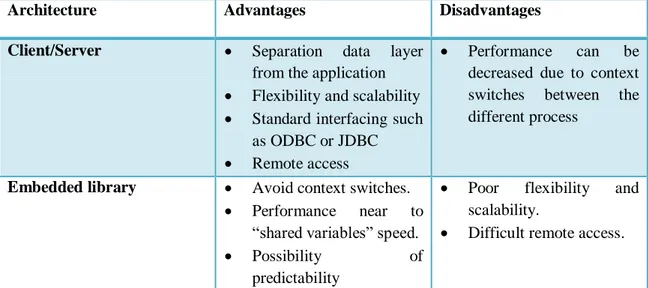
There are mainly two different database architecture approaches, client/server and embedded library. Both of them have several advantages and disadvantages, thus in the following it will be explained the main features of each and their strongest and weakest points (see Table 1).
The client/server architecture [27] [24] separates the data layer from the application (see Figure 5). The database and the data are stored in the database server process. Separate client processes requests the information from the server. In this way, the flexibility, the scalability of the database is increased since every update or change might be done in the server without knowing of the clients. Moreover, since all data is centralised in the server, the clients are able to access to updated data every time which increases the consistency of the system. The client/server architecture also provides standard interfacing as ODBC or JDBC [27] (see the Table 1).
From a real-time perspective, the client/server application has the disadvantage of the unpredictability inherited by the context switches between the several processes that compose the architecture and also the scheduling of those processes.
The embedded library architecture is [27] featured by including the database within the application process; hence, the database is embedded in the application as a library (see Figure 6).
There are several advantages of using this kind of architecture as the elimination of the context switches since database and application are in the same process. Moreover, due to the fact that both database and application are embedded in the same process, the database performance for accesses is close to “shared variables” speed [27]. Thus, by the elimination of context switches and performance accesses near to “shared variables” speed, this architecture increases the possibility of predictability.
In contrast, the scalability and the flexibility of the database is decreased due to many reasons: Since the databases are embedded in the application process, it is not possible to modify the database at runtime. In addition, since the database is embedded within the application, the communication between different applications becomes more difficult due to the fact that for each pair of applications it is necessary to design a new interface between them to carry out the communication process (see Table 1).
The following table shows a comparative between both architectures:
Architecture Advantages Disadvantages Client/Server Separation data layer
from the application
Flexibility and scalability
Standard interfacing such
as ODBC or JDBC
Remote access
Performance can be
decreased due to context
switches between the
different process
Embedded library Avoid context switches.
Performance near to
“shared variables” speed.
Possibility of
predictability
Poor flexibility and
scalability.
Difficult remote access.
CHAPTER 3.
RELATED WORK
This section presents the main features of three commercial real-time databases, namely, Mimer SQL Real-Time Edition, eXtremeDB 4.0 Standard Edition and Oracle Times Ten In-Memory database. Furthermore, architecture, concurrency control and performance are some of the features which will be explained for each database.
3.1 MIMER SQLREAL-TIME EDITION
Mimer SQL Real-Time Edition is an in-memory database management system featured by its predictability, scalability and zero maintenance [19]. This database is suitable for automotive, process-control and robotic applications. One of the main characteristics of Mimer Real-Time Edition is support for both hard real-time and non-real-time database access integrated in only one database management system. In addition, Mimer RT provides fully deterministic response-times which are supported by well-proven real-time algorithms researched in collaboration with MRTC (Mälardalen Real-Time Research Center). Moreover, this database, support fully ISO/ANSI SQL and has a footprint less than 300kb [19].
In order to improve the performance, Mimer RT use Database Pointers for the real-time accesses (see Figure 9). By using Database Pointers, the real-time accesses are carried out with the pointers while the non-real-time accesses can be done by SQL queries. Thus, this mechanism allows predictability, and fine-grained access to data within the database. As it is mentioned in [19] “Database pointers combine the performance and predictability of shared variables with the power of an SQL database.”
Mimer support data types such as structures, arrays vectors, blobs and lobs, date times, UNICODE, etc. however for non real-time access. Mimer RT API currently supports int, string, short, timestamp, and double [24]. Moreover, Mimer supports
3.1.1 PERFORMANCE
Mimer SQL Real-Time Edition claims to be a predictable, scalable and zero maintenance database management system for embedded real-time systems which combines hard real-time and non real-time accesses [19].
Focusing on the transaction performance, it is noticed that writing an integer value takes 0.11 microseconds, and reading and integer takes 0.14 microseconds (in an Intel Core2Duo 2.33GHz microprocessor). For more information about the response times see the Table 2.
Table 2. Mimer SQL Real-Time Performance [19]
3.1.2 CONCURRENCY CONTROL
Mimer SQL Real-Time Edition [24] uses a different concurrency control depending on which API is being used to make the transactions. The non real-time SQL part of Mimer uses Optimistic Concurrency-Control while the real-time API uses a lock-based real-time concurrency-control [24] (see Figure 7) and database pointers. In the Figure 7 and Figure 8 are stated the differences in response time of using database pointers and using a traditional concurrency control as 2PL-HP.
Figure 7. Response time for hard transactions using database pointers [14]
Figure 8. Response time for hard transactions using 2PL-HP [14]
3.1.3 ARCHITECTURE
Mimer SQL Real-Time is based on a client/server architecture combined with an embedded library (see Figure 9). Mimer uses the server only for SQL access and real-time initialization and the embedded library with direct access to the database from the clients. That is, Mimer is thereby combining the advantages of the client/server model, with the performance and predictability of the embedded library.
Figure 9. Overview of Mimer SQL Real-Time Edition architecture [27]
3.2 EXTREME DBSTANDARD EDITION
eXtremeDB [18] is an in-memory embedded database system designed for embedded systems and other domains where high performance, small footprint or compact storage are required.
eXtremeDB stores the data in the same form which is used by the application, removing overheads related with caching and translations. Its engine is re-entrant, allowing multiple transactions and supporting the ACID properties. Moreover, eXtremeDB claim to have a small footprint “approximately 100k” [18]. eXtremeDB supports data types like structures, arrays, vectors or BLOBs. Finally, eXtremeDB support several embedded platforms (VxWorks, INTEGRITY OS, QNX 4.x, QNX 6.x, etc.), server and desktop platforms (Sun Solaris 8 and Solaris 9, HP-UX 11.x, Linux distributions, Classic Windows platforms) and development environments (gcc 2.95 and higher, Microsoft Visual Studio (C/C++, .NET), GreenHills Multi) [18].
a) Soft or hard real-time requirements, b) Dynamic data streams, and
c) Cost-effective (limited) hardware resources.
3.2.2 CONCURRENCY CONTROL
a) Multiple Reads Single Write (MURSIW)
This is a traditional lock-based transaction mechanism where readers do not block between each other, but writers need to acquire locks to complete their transactions. This mechanism supports the ACID properties, but the concurrency level is low [10].
b) Multi-Versioning Concurrency Control (MVCC)
This is a multi-versioning transaction mechanism that enhances applications‟ concurrency. With this mechanism, transactions can see a snapshot of the data while they are querying the database, thus the transactions are protected from inconsistent views caused by other transactions working in the same set of objects. The MVCC allows the applications to choose which isolation level they want for their transactions, these are the levels available [10]:
Read committed: When this level is used a transaction always reads committed data. The transaction will never read data that another transaction has changed and not yet committed, but it does not ensure that the data will not be changed before the end of the transaction [10].
Repeatable read (snapshot): This is the default isolation level in eXtremeDB. When a transaction runs at repeatable read level, it reads a database snapshot (data and cursors) as of the time when the transaction starts. When the transaction concludes, it will successfully commit only if the values updated by the transaction have not been changed since the snapshot was taken. Such a write-write conflict will cause the transaction to roll back. Also note that the snapshot level does not serialize transactions [10].
Serializable: This level applies an exclusive lock to all write transactions, i.e. no other write transactions can run at the same time [10].
3.2.3 ARCHITECTURE
eXtremeDB is based on a embedded library architecture (see Figure 6) which is featured by an embedded library within the application. This is carried out by an application provided by McObject which reads and schema file (.mco) and parse it into a library file (.h) at compile time. The fact that compiling the schema with the application makes data accesses efficient and predictable, however, at the cost of a dynamic schema, i.e., changes to the structure of the database require that the application is recompiled.
3.3 ORACLE TIMES TEN IN-MEMORY
Times Ten [11] (see Figure 10) is a memory-resident relational database which is featured by a high number of transactions per second in average and also a low response
In order to improve the performance, Times Ten allocate the entire database in main memory and try to optimize the data structures and access algorithms; as well, Times Ten libraries embedded within applications. In the Figure 10 it is shown an overview design of Times Ten [11].
Figure 10. Times Ten overview design [11]
3.3.1 PERFORMANCE
a) Transactions
During one test [17] performed by Oracle on an Intel E5450 (8-way @ 3GHz) Times Ten reaches 1,265,867 “read transaction” per second, on average, with 8 concurrent processes; with only one process the read rate transactions was 246,623 per second, on average.
On the other hand, during the same test, Times Ten reached 188,000 “update transactions” per second, on average, with 8 concurrent processes; with only on process the update transactions rate was 56,000 per second, on average.
b) Response Time
Regarding at the response time in Times Ten, and using the same test as above, for the “read transactions” they claims that the average response time is 5 microseconds; and for the “update transactions” the average response time is 15 microseconds [17].
3.3.2 CONCURRENCY CONTROL
a) Read committed isolation
This is the default isolation level in Times Ten (see Figure 11). Read committed isolation provides the readers use a different copy of the date from writers. In this way, readers are not blocked by writers, and writers only block the other writers. In order to achieve this mechanism Times Ten uses versioning [11].
Figure 11. Read commited isolation scheme [11]
b) Serializable isolation
Figure 12. Serializable isolation [11]
3.3.3 ARCHITECTURE
Times Ten is [11] based on a client/server architecture combined with a embedded shared library (see Figure 13), as it was explained in section 2.3.4, this kind of architectures has several advantages as supporting for remote accesses, standard interfaces as JDBC, ODBC or JTA and XA for distributed transactions, separation between data layer and application layer, etc.
CHAPTER 4.
THE BENCHMARK APPLICATION
This chapter explains how the benchmark application is designed, going from a system overall through the GUI description, the real-time application and the real-time system.
4.1 SYSTEM OVERALL
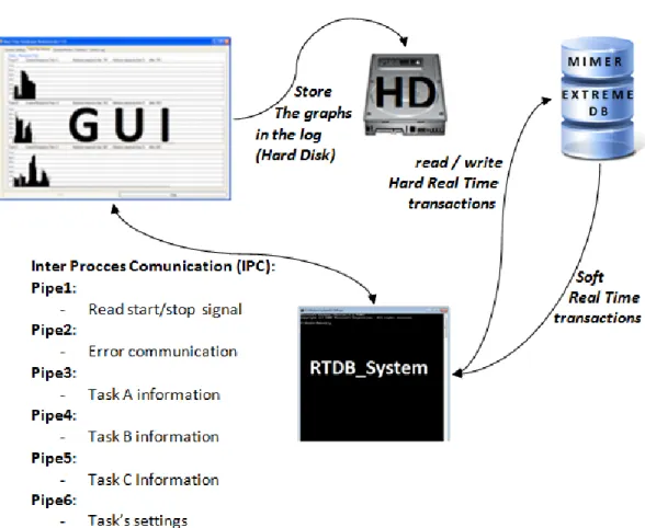
The system is comprised of two processes: the real-time application and the Graphical User Interface, GUI (see Figure 14). The real-time application is responsible for creating the threads that compounds the real-time system, setting up the databases and reading all the parameters needed from the pipe that connects the real-time application with the GUI. The information taken from the pipes is used in order to setting up the real-time system. Information such as number of tasks, period or deadline is sent from the GUI to the real-time application. The real-time system aims to simulate a typical real-time system featured by sensor, control task, actuator and performs read/write transactions in the databases.
Finally, the Graphical User Interface is responsible of reading all the information sent by the real-time application through the pipes, i.e. the information sent is the response time of each task. In addition, the GUI calculates the statistics and displays the results in an easy to understand way for the user.
The results displayed in the GUI are:
a) A graph representing the response time in a timeline for each task which are stored in a log in the hard disk.
b) A set of statistics displaying worst-case, average and best case response time for each task. Moreover, the deadlines misses are represented.
d) The CPU time consumption for the real-time application.
The parameters configurable in the GUI are:
a) Number of tasks running in the real-time application. b) Period of the tasks.
c) Deadline of the tasks. d) Database.
4.2 THE REAL-TIME APPLICATION
The real-time application implements the real-time system and also implements other functions such as inter-process communication, and setting up the real-time systems.
In summary, the tasks performed by the real-time application are:
a) Read the tasks settings (read_tasks_settings). This task is responsible for reading the information received from the GUI through the pipe and setting the system up according to it. Parameters such as number of tasks, period or deadline are read.
b) Read the start/stop signal from the pipe that connects the real-time application with the GUI in order to launch and stop the real-time system. c) Launch and finish the real-time system threads: This task is responsible for
launching the real-time system threads and setting up the databases. Depending on what database the user chooses, either Mimer or eXtremeDB threads are created (“mimer_routine” or “mco_routine” respectively). This task set up the respective database and launches the real-time system tasks. Moreover this task is also responsible for finishing the real-time system.
4.3 THE REAL-TIME SYSTEM
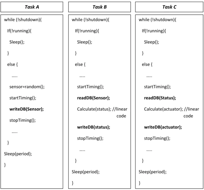
The real-time systems aim is to simulate a typical real-time system, which usually is made up of a sensor, some kind of controller process and an actuator. According to this, three different tasks: task A, task B and task C, have been developed.
b) Task B simulates the controller processes, reading the sensor values from the database, calculating the status value of the system depending on the sensors, and writing the actuator value in the database.
c) Task C simulates the actuators; it reads the corresponding status value from the database and actuate according to this value, in this case it writes the actuator back in the database.
One of the most important features of those tasks is that apart from the database calls, those tasks are exempt from locks, blocking and are written with linear code, i.e. no loops, no function calls, etc (see Figure 15). This is an important feature for those tasks since non-linear code can introduce unpredictability (different execution time for the same tasks) within the tasks and if it would occur, the evaluation process would become more difficult since it would be impossible to determine whether the execution time vary due to the database calls or because of the code variations. In addition, those tasks are executing at real-time priority.
Finally, in order to evaluate the real-time system under different workloads and conditions, the real-time system can be configured during run-time. Configurable parameters include number of task instances running, period of tasks and task deadlines.
Figure 15. Tasks schema
4.4 THE GRAPHICAL USER INTERFACE
The Graphical User Interface, GUI, consists of two modules, the Inter Process Communication (IPC) and the GUI itself that is implemented in C#. The IPC module is implemented by using named pipes [25]. On the GUI side those named pipes are implemented as a server that create the pipe, and also manage the message sending and
while (!shutdown){ If(!running){ Sleep(); } else { ….. sensor=random(); startTiming(); writeDB(Sensor); stopTiming(); ….. } Sleep(period); } while (!shutdown){ If(!running){ Sleep(); } else { ….. startTiming(); readDB(Sensor); Calculate(status); //linear . code writeDB(status); stopTiming(); ….. } Sleep(period); } while (!shutdown){ If(!running){ Sleep(); } else { ….. startTiming(); readDB(Status); Calculate(actuator); //linear . code writeDB(actuator); stopTiming(); ….. } Sleep(period); }
When the information is available and in the correct format, the statistics are calculated and stored in their own variables. The response time is displayed in a timeline graph which makes the information easier to understand. When the timeline is full the graph is saved in the graph log and a new graph is created. The GUI itself is implemented through a tabbed window, since the application is designed for both tactile screen and normal PC‟s. In order to satisfy the user requirements, five tabs have been added: System Settings, Real-Time Monitor, System Monitor, Statistics and System Log.
Focusing on the tabs description, first of all, in the initial screen is the “System settings” tab (see the Figure 16). In this tab it is possible to adjust the task settings such as period (200 – 10.000 ms), deadline (10-200 µs) and number of tasks (0-500 tasks). In addition, it is possible to set which database (eXtremeDB or Mimer) that is used during the test. The user can start the application by selecting the database and clicking the start button, and then by dragging the scroll bars the user can change the tasks parameters during the application‟s execution. Since all the parameters can be modified at runtime, it provides more flexibility to the application and makes the evaluation process easier.
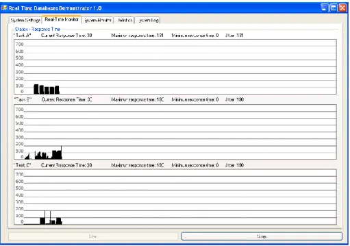
In the “Real-Time Monitor” tab (see Figure 17) the application generates three graphs that corresponds with the simulated real-time system (task A, task B and task C). The graphs represent the response time for each transaction in each task. Furthermore, above each graph, relevant information of each task as the current response time, the maximum response time, the minimum response time and the jitter is displayed. Thus, the user can supervise and analyse the system behaviour easily at runtime. Moreover, if the user is busy doing other tasks, the graphs will be saved in a log folder with the a name like this „task[A-B-C]_databaseName_dd.mm.yyyy_hh:mm:ss.bmp‟ located in c:\graph_log\task[A-B-C]\. Since the graph files are named with the database name, the task name and their timestamp, it makes the analysis after runtime easier.
Figure 17. Real-Time Monitor tab
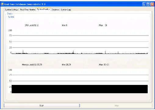
In the “System Monitor” tab (see Figure 18) the application generates a graph displaying the total CPU load percentage and the main memory load percentage. Furthermore, each parameter displays the maximum value reached as well as the minimum and current value. Those graphs provide the user with information about the system utilization apart from the real-time system information; this information can be used to better understand the real-time system behaviour.
Figure 18. System monitor tab
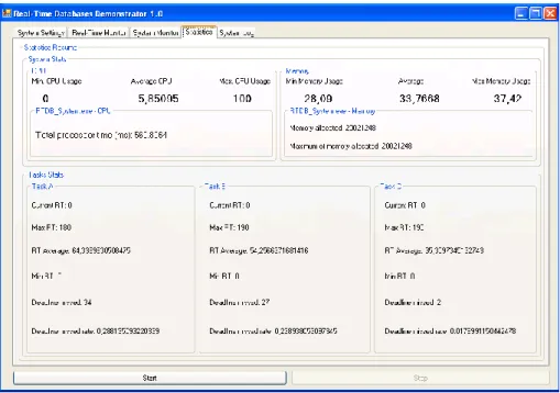
The “Statistics” tab (see Figure 19) is one of the most important tabs if the user want to analyse the real-time system behaviour. It displays the system status and provides the user with information regarding minimum, maximum, and average CPU usage. Apart from the CPU information, the physical memory utilization information is represented by the maximum memory utilization, the minimum utilization and the average; the physical memory consumption for the real-time process is shown as well. The “Statistics” tab also includes information about each task. Parameters shown are the current response time that represents the actual response time of its task; the maximum response time which represent the maximum response time reached; the minimum response time obtained; the number of missed deadlines and the missed deadlines rate (missed deadlines per transaction). Using this information described above, and the information extracted from the real-time monitor and the system monitor, the user is able to obtain a good evaluation of the system behaviour.
Figure 19. Statics tab
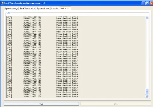
The “System log” tab (see Figure 20) gather information about warnings and errors occurred during the system execution as, for example, warnings from the sensors or errors caused by missed deadlines. The information is displayed in the following format: [Error/Warning] + [Timestamp] + [Error / Warning description] + [Deadline value, if deadline error]. The system log becomes very useful if combines itself with the other information gathered by the application, for example, the system log combined with the graph log make the evaluation process easier since it could be carried out after runtime.
Figure 20. System log tab
To summarize, the application provides several tools to analyze and evaluate real-time databases. Since the application allows the user to set up the system with a range of parameters, the user can develop every kind of test bench, modify them at runtime and study how the database behaviour is changing. In addition, given that the application stores every graph in the log and also by using the system log information that stores the timestamp of every error, the user is able to make the evaluation after runtime.
CHAPTER 5.
THE BENCHMARK SETUP
Since the aim of this thesis is to test the real-time features as predictability and response time, it is necessary to design a set of test cases and a methodology to carry out the test process. Five test cases are created and they will be executed during five minutes for each database. The parameters set in the test cases are: Number of task running, period of task, deadline of task and database. The results obtained from the test are: Maximum response time, minimum response time and average response time for each task. Furthermore the results includes missed deadlines, a graph displaying the response time in a timeline and the total CPU time used for the real-time process.
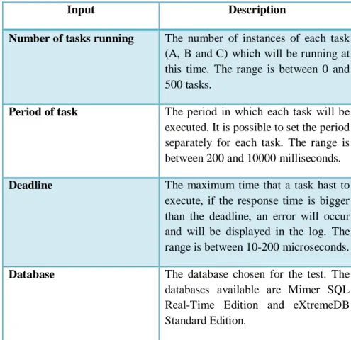
The Table 3 describes the input test‟s parameters.
Input Description
Number of tasks running The number of instances of each task (A, B and C) which will be running at this time. The range is between 0 and 500 tasks.
Period of task The period in which each task will be executed. It is possible to set the period separately for each task. The range is between 200 and 10000 milliseconds.
Deadline The maximum time that a task hast to execute, if the response time is bigger than the deadline, an error will occur and will be displayed in the log. The range is between 10-200 microseconds.
Database The database chosen for the test. The databases available are Mimer SQL Real-Time Edition and eXtremeDB Standard Edition.
In the Table 4 it is described the meaning of the output test‟s result:
Output Description
Maximum response time The maximum response time got from the test for each task. It will be given in microseconds.
Minimum response time The minimum response time got from the test for each task. It will be given in microseconds.
Average response time The average response time got from the test for each task. It will be given in microseconds.
Missed deadlines The total number of deadline missed of each task.
Missed deadlines rate The rate of missed deadlines per transaction.
Graphical representation of the response times in a timeline
Is a graphical representation of the response time. In the Y-axis is represented the response time in milliseconds [0-90 µs] and in the X-axis is represented the transaction. Each line represents one transaction.
Total CPU time The total CPU time assigned to the
real-time process. Given in
microseconds Table 4. Test case output description
In order to make a linear and correlated test, and since the goal is to evaluate the database behaviour under different situations but keeping a linear progression in our tests, the period of the tasks will be set at the minimum and the number of task will be
5.1.1 TEST CASE 1
Parameter Value Value Number of tasks
running
100 tasks 100 tasks
Period of task 200 ms 200 ms
Deadline 100 µs 100 µs
Database Mimer RT eXtremeDB Table 5. Test case 1 description
5.1.2 TEST CASE 2
Parameter Value Value Number of tasks
running
200 tasks 200 tasks
Period of task 200 ms 200 ms
Deadline 100 µs 100 µs
Database Mimer RT eXtremeDB Table 6. Test Case 2 description
5.1.3 TEST CASE 3
Parameter Value Value Number of tasks
running
300 tasks 300 tasks
Period of task 200 ms 200 ms
Deadline 100 µs 100 µs
Database Mimer RT eXtremeDB Table 7. Test Case 3 description
5.1.4 TEST CASE 4
Parameter Value Value Number of tasks
running
400 tasks 400 tasks
Period of task 200 ms 200 ms
Deadline 100 µs 100 µs
Database Mimer RT eXtremeDB Table 8. Test Case 4 description
5.1.5 TEST CASE 5
Parameter Value Value Number of tasks
running
500 tasks 500 tasks
Period of task 200 ms 200 ms
Deadline 100 µs 100 µs
Database Mimer RT eXtremeDB Table 9. Test Case 5 description
5.2 PLATFORM CONFIGURATION
The following section describes the platform characteristics where the tests has been executed. The platform is a Toshiba Satellite A500-13z with the characteristics described in the Table 10
Technology Processor: Intel Core 2 Duo T9600, chipset Intel GM45 Express and Intel WiFi Link 5100
Clock frequency: 2.80 GHz Front side bus: 1066 MHz
2nd level cache: 6MB
Operative System
Windows 7 Professional Edition
Windows XP Professional running on Windows Virtual PC
Main Memory 4096 MB DDR2 RAM (800MHz) Table 10. Platform characteristics
5.2.1 LIMITATIONS
Throughout the thesis there have been some limitations which have influenced the thesis process. First of all, since Windows is a general-purpose operating system it can introduce some unpredictability. Thus, some unexpected spikes could appear in the response times, i.e. response times much bigger than the other even when all of them are executing the same code; this also happens when the process are executing at real-time priority which makes the problem even worse. This is because Windows, as a general purpose operating systems do not control the worst case blocking of internal interrupts, as well as not providing a deterministic scheduling algorithm. The spikes in the response-time graphs can therefore be identified as unpredictable operating system interrupts. Hence, it was decided to filter those transactions which are far away of the real response time for the transactions in order to approximate the results to the results which could be got from the execution on a real-time operative system.
The transactions filter has been set at 100 µs, i.e. every transaction bigger than 100 µs will be discarded by the application. Even though discarding those spikes it is suspected that some smaller spikes are caused by external interruptions triggered by the operative system. In order to clarify the suspicion that the operative system introduces
and see whether this big spikes appear or not. And finally decide if either disregards those spikes in a second filter or not.
In addition, at the beginning the thesis was thought to be developed including eXtremeDB, Mimer SQL Real-Time Edition and Oracle Times Ten. But during the implementation and configuration process of Oracle Times Ten there were some critical troubles and Oracle did not provide technical support, so we must to give up in the Oracle TimesTen implementation.
CHAPTER 6.
BENCHMARK RESULTS
This chapter presents the results obtained from the tests. For each test case two tables are created, one for eXtremeDB, one for Mimer and another one for the execution without database calls. In those tables the parameters described in the Table 4 are shown. In order to make the reading reviewable, a more extensive results are shown in the Appendix A.
First of all a worst-case response time analysis is performed, without the usage of a database in order to clarify the assumptions done about the unpredictability introduced by the operating system in the section 5.2.1. This is our baseline test. After establishing an evaluation baseline, a worst case response time analysis is carried out for the two commercial databases. Then, an average response time analysis is done for each task and database.
6.1 WORST-CASE RESPONSE TIME ANALYSIS
In this section a worst-case response time analysis is done. The analysis is carried out by getting a representative graph, a snapshot of the full execution. Since the execution of the benchmark application is carried out on a Windows operative system which is a general purpose operating system, as was discussed in 5.2.1, it is suspected that the operative system itself can introduce unpredictability in the application.
In order to find out how the operating system influences the application, a baseline execution without any database calls, unpredictable loops or blocking has been performed (see Figure 21). This code executed under the same conditions as the test cases using databases.
6.1.1 NO DATABASE WORST-CASE RESPONSE TIME
After testing the application with no database calls, the following graph was obtained (see Figure 21):
Figure 21. No database response time.
As can be seen in Figure 21 there are some spikes along the graph. This is contradictory since the code executed is linear and exempt from blocking (see Figure 15). Hence, the response time for every task should be constant. The only explanation to these spikes is that the operating system interrupts the real-time tasks even when they are executing at real-time priority. Therefore, it can be concluded that the operating system itself introduce unpredictability in the real-time application.
The fact that the operating system introduces unpredictability itself makes the evaluation of the databases more difficult. Due to this, the test case results obtained will not be definitive, but more reflect an indication regarding the worst-case response time. Ideally the evaluation should have been performed on a real-time operating system, but since this is not within the scope of this thesis, the evaluation will be performed as accurate as possible.
As can be noticed in Figure 22 there is a clear pattern where all the transactions are in the range 0-10 µs. Therefore, the spikes which are out of the pattern are disregarded from the evaluation, see the spikes crossed out in the Figure 22.
In contrast, it is not possible to determine if all the small spikes which are enlarged within the box in the Figure 22 are because of the operating system; hence, they will be included within the evaluation.
6.1.2 EXTREMEDB WORST-CASE RESPONSE TIME
The eXtremeDB‟s worst case response time evaluation will be carried out considering the assumptions made in the section 6.1.1, i.e. the spikes induced by the operating system will be disregarded from the evaluation. A snapshot of the execution disregarding the spikes looks like (see Figure 23):
Figure 23. eXtremeDB response time disregarding the operating system interruptions
Comparing the snapshot execution of eXtremeDB and the execution of the code without database calls, it can be noticed that there are more big spikes in the eXtremeDB‟s execution. The reason could be the execution time itself, i.e., the execution time of the code without database calls executed in approximately 4µs while eXtremeDB executed in around 14 µs, hence eXtremeDB‟s execution is 3.5 times longer than without the database and therefore the probability of being interrupted is 3.5 times bigger.
After disregarding the spikes which are considered to be caused by the operating system, it is possible to focus on the range between 0 µs and 20 µs. Focusing in this range, it is possible to evaluate the database behaviour more accurate. As it is shown in
Figure 24. eXtremeDB's worst-case response time estimation
6.1.3 MIMER WORST-CASE RESPONSE TIME
As in eXtremeDB‟s worst case evaluation, the Mimer‟s worst-case evaluation is considered using the same assumptions explained in the section 6.1.1. Thus by disregarding the spikes from the execution‟s snapshot it is obtained the following graph (see Figure 25):
Figure 25. Mimer response time disregarding the operating system interruptions
Comparing this snapshot (see Figure 24) with the no database callings (see Figure 21) it can be noticed that there are more spikes in Mimer‟s snapshot execution compared to the execution without database calls, but not that much. The explanation of this could be that Mimer‟s average response time is closer to the no-database response time; while the no-database code average execution time is 4µs approximately, Mimer average execution time is around 6µs, which means that Mimer has 1.5 times more probability of being interrupted than the code without database calls.
possibility that those transactions have been interrupted due to the operating systems issues. Thus, it can be figured out other worst-case response time estimation. Disregarding those transactions which are above 10 µs, it can be noticed that the majority of the transactions fluctuate between 4 µs and 7-8 µs as estimation.
Figure 26. Mimer's worst-case response time estimation
Therefore, there are two possible worst-case response time estimations; on the one hand, a possible estimation can be around 12 µs since there are a few spikes that reaches this value apart from the discarded before (see the red line in the Figure 26). But, on the other hand, regarding the Figure 26, it can be noticed that the majority part of the transactions are fewer than 8 µs, and thus, it also can be the worst-case response time estimation for Mimer. Since it is not possible to determine whether those transactions are caused by the operative system or not, thus, it can be concluded that the worst-case response time estimation for Mimer is 12 µs.
6.1.4 WORST-CASE RESPONSE TIME SUMMARY
In this section, the results from the worst case response time analysis are summarized (see Table 11)
Database Best Case Response Time Worst Case Response Time Fluctuation eXtremeDB 7 µs 18 µs 11 µs Mimer 4 µs 12 µs 8 µs
![Table 2. Mimer SQL Real-Time Performance [19]](https://thumb-eu.123doks.com/thumbv2/5dokorg/4689007.122921/32.892.132.810.502.653/table-mimer-sql-real-time-performance.webp)
![Figure 9. Overview of Mimer SQL Real-Time Edition architecture [27]](https://thumb-eu.123doks.com/thumbv2/5dokorg/4689007.122921/34.892.146.747.126.321/figure-overview-mimer-sql-real-time-edition-architecture.webp)