1
fanafvddffdfadfknbafddgdffddfdmdlfaldg
Visual Studio Add-in for Proxy Object
Code Generation
Master Thesis in Computer Science
Student
Gopalakrishnan Thangavel
gtl09001@student.mdh.se
Supervisor
Frank Lüders
frank.luders@mdh.se
Examiner
Kristina Lundqvist
kristina.lundqvist@mdh.se
Date: 20-10-2013
2
DEDICATION
3
Abstract
In recent years, Component models have become common for desktop and server-side applications. But it has not obtained such importance in case of embedded real-time systems. Therefore, there has been a lot of research undergoing for introducing such component models for embedded real-time systems. This thesis work proposes an alternative approach for doing this, by the generation of proxies. The idea is to provide an extension to an existing binary component and modify it to adapt to the targeted real-time operating system. Rather than modifying the existing component, a new component is generated, which is called as the proxy component. This newly generated proxy component provides the same method implementation as the original component and also provides some additional services. These services enable these components to meet the needs of targeted embedded real-time systems. In order to achieve this, a Visual Studio 2008 add-in has been created. This add-in is capable of inspecting an existing Smart Device Component and visualizes the Classes, Interfaces and Methods in the original component in its UI. In addition to this, the add-in also shows the available services to be included in the proxy component. The UI of the add-in is designed in such a way that, the user is able to select the services, which should be included in the proxy component. Based on the user’s selection, the add-in generates the proxy component with the additional services.
4
Table of Contents
1. Introduction _______________________________________________________________ 7
1.1. Problem Statement _____________________________________________________________ 8 1.2. Technology adaptation and Scope _________________________________________________ 8 1.3. Report Outline ________________________________________________________________ 9
2. Component Based Software Engineering _______________________________________ 10
2.1. Software Component __________________________________________________________ 10 2.2. Software Component Model ____________________________________________________ 11 2.3. Software Component Specification _______________________________________________ 11 2.4. Component Object Model ______________________________________________________ 12
3. Real Time System __________________________________________________________ 14
3.1. Embedded System ____________________________________________________________ 14 3.2. Embedded Real Time System ____________________________________________________ 14 3.3. COM in Real Time Embedded Systems ____________________________________________ 15 3.4. Component Technologies for Embedded Real Time System ____________________________ 15 3.5. Software Component Services for Real-Time Embedded System _______________________ 15 3.5.1. Proxy Object _____________________________________________________________________ 16
4. Implementation of Visual Studio Add-in ________________________________________ 19
4.1. Visual Studio _________________________________________________________________ 19 4.1.1. Extensibility ________________________________________________________________________ 19 4.1.2. Visual Studio Add-Ins ________________________________________________________________ 20 4.2. User Manual for Add-In ________________________________________________________ 20
5
4.3. Example Component ___________________________________________________________ 27
5. Code Generator ___________________________________________________________ 29
5.1. Smart Device Project___________________________________________________________ 29 5.2. VC++ Source Code generation ___________________________________________________ 30 5.3. Generated Code ______________________________________________________________ 31 5.4. Discussion ___________________________________________________________________ 32
6. Conclusion and Future Work ________________________________________________ 333 7. References ______________________________________________________________ 355 Appendix __________________________________________________________________ 377
A. Original Component Header File _______________________________________________ 377
B. Original Component CPP File __________________________________________________ 388
C. Original IDL File ______________________________________________________________ 39
D. Generated Header File ________________________________________________________ 40
E. Generated CPP File ___________________________________________________________ 41
6
List of Figures
Figure 1 Implementing a logging service though a proxy object ... 18
Figure 2 Generating a proxy object for a Component Service ... 18
Figure 3 Visual Studio Add-in ... 21
Figure 4 DLL Browser ... 22
Figure 5 New Proxy Project Wizard ... 23
Figure 6 Proxy Project Created ... 24
Figure 7 Select Methods ... 25
Figure 8 Proxy Created ... 26
7
1. Introduction
Component Based Software Engineering (CBSE) is one of the most widely used practices for developing software from smaller software parts called software components. CBSE reduces the development time and increases productivity of the software and also increases quality of the software [1]. As a nice bonus, CBSE also uses standard component models, which usually comprise of components’ design-time composition and/or run-time interaction. Component models are a set of rules and standards for component based development and are usually accompanied by one or more component technologies. The most notable component models used in the case of desktop applications development are JavaBeans and ActiveX and the most notable component models used in the case of Distributed information systems are Enterprise Java Beans (EJB) and COM+.
Component models are widely used in case of desktop applications and distributed information systems [4]. But the usage of Component Models is limited in case of embedded real-time systems. The adaptations of CBSE in embedded real-time systems development cannot be easily done, because it has significant risks and there are many costs effective parameters needs which must be carefully evaluated [1]. The main reason for this limitation is the existence of certain constraints such as limited storage and limited power in case of those embedded real-time systems. Therefore, usage of Component Based Development in Embedded real-time has become more challenging topic nowadays.
In the recent years, there have been researches going on towards developing new component models for embedded and real-time systems [2]. As a result, component models such as KOALA, PECT, PECOS, Rubus Component Model, etc. emerged [11]. These Component models are based on static configurations of source code components and they target only narrow application domains. But, there is an alternative way which uses component models with is based on binary components. The advantage of this alternative approach is that, these component models target broader application domains.
8
This thesis work aims at providing such component model, which provides an extension to an existing component model and adapt it to the target environment.
The work presented in this thesis is an inspiration of the theses [4] and [6]. Both the above mentioned thesis works aimed at the development of Visual Studio add-in for adding services to Smart Device Components. Hence they generated the Visual C++ (VC++) proxy code using Visual Studio Automation. Even though they are successful in the generation of proxy code, their work has two significant limitations which has been explained in Section 5.4.
1.1. Problem Statement
The purpose of this Master thesis is to develop a Visual Studio Add-In. A Visual Studio add-in is a component, which is dynamically loaded by an application called the host application. This add-in then becomes the part of the host application. The developed add-in is capable of inspecting an existing Smart Device Component and generates the proxy component for it. A Proxy component is a Component, which acts as a substitute to the original Component. It provides the same implementations as that of the original Smart Device Component and also provides some additional services like logging functionality, to the original component. Generation of the proxy component is done by using Visual Studio’s Automation Object Model API. Visual Studio’s Automation Object Model API is the API provided by Visual Studio to automate repetitive tasks through automatic code generation. Both the original Component and the proxy component are COM Smart Device Components.
1.2. Technology adaptation and Scope
The Add-In is developed using Visual Studio 2008, since it is the most important requirement of the thesis. The original Smart Device Component is a DLL file which is inspected by the Add-in for generating the proxy component. When the original component is loaded in the add-in, it visualizes the Classes, Interfaces and Methods present in the .dll file using Reflection. The Code generator is then capable of generating the proxy code for proxy component by using the Visual Studio’s Automation Object facility. The output of the Code Generator is a Smart Device Project, which should be
9
compiled manually to get the proxy component (DLL file). During proxy code generation, the Visual Studio’s Automation Object model provides facilities for generating a new solution with a Smart Device Project using VCCodeModel API [12]. It also enables us to create Smart Device Project specific files such as C++ (.cpp) file, Header (.h) file, Registration (.rgs) file, Resource (.res) file, and IDL (.idl) file using VCCodeElement [13]. The original component is represented by a DLL (.dll) file, which is generated by a Smart Device Project.
1.3. Report Outline
Chapter 2 deals with the explanation of Software Component, Component Models and Component Based Software Engineering.
Chapter 3 explains the concept of Embedded Systems, Real Time Systems and Embedded Real Time Systems.
Chapter 4 starts with a brief introduction to the Microsoft Visual Studio. Then Visual Studio Extensibility and Visual Studio Add-ins are explained. Finally, User Manual for using the Add-in generated in this thesis work is given.
Chapter 5 describes the Code Generation by comparing the sample original component code and the proxy component code
Chapter 6 deals with the conclusion and future work of the thesis. Chapter 7 provides the list of references used.
10
2. Component Based Software Engineering
During the last decade, there have been a lot of development and revolutionary changes in the field of Software Engineering. At the same time, there is a rapidly growing demand for rapid and cost effective development of large scale, complex and highly-maintainable software systems which introduces major challenges in the Software field [5]. But still there has always been need for developing software at low cost and in a reduced time. A reasonable solution to this problem could be the introduction of reusability concept in the field of Software Engineering. Even though software reuse is quite common in the field of Software Engineering, it is not well defined. This drawback in reusability can be compensated by Component-based development (CBD). CBD is an emerging approach, which reestablishes the idea of reuse and introduces new elements. However, CBD has its own drawbacks discussed as discussed in this paper [1]. Hence it requires an advanced approach which governs its component aspects. This drawback can be compensated by Component Based Software Engineering (CBSE). CBSE is concerned with the development of software by assembling existing smaller pieces of software modules called Software Components [2].
2.1. Software Component
Software component is a software element that confirms to a Component Model, which can be independently deployed into an existing Software System. According to [2], Software Components is considered the heart of CBSE. This statement indicates the importance of Software Components in CBSE. Software Components are always developed with well-defined interfaces and their functionalities are as agreed upon [1]. Interfaces are said to be an abstraction of the behavior of a component [8]. In other words, interfaces depict the usage of a component. Communication between the component and the target Software System takes place through its set of interfaces. In order to facilitate the use software components in other projects the components must be well specified, easy to understand, easy to adopt, easy to deliver and deploy and easy to modify and replace [1].
11
2.2. Software Component Model
Object oriented technologies usually provide the most important features like Abstraction, Encapsulation, Polymorphism, Persistence etc. for today’s Software Development. But they fail to support enough reusability support for software development. Component Models overcome the limitations of Object Oriented technologies by providing enough support for reusability. According to [1], “A component model is defined as a set of standards and conventions used by the component developer”. Among all the Software Component Models, the most important Component Models are Java Beans, COM, COM+, .NET, OSGI etc. These component models provide enough support for developing Component Based Software systems from the scratch [6]. While using Component Models for CBD, it usually provides support for implementation, composition, deployment and maintenance support, thought the lifecycle of Components.
2.3. Software Component Specification
Software components are always accessed through its set of interfaces. The users of these components should always have enough information about these interfaces, in order to invoke these interfaces. This information required by the users is specified in the form of Specification, which is known as Software Component Specification. Software Component Specification provides precise and complete information for the component user as well as the developer of the component [1]. Specification of a Software Component can be grouped into two different types. The first one is the developer’s view and the second one is the user’s view. The first view (Developer’s View) aims at describing the internal structure of the component. This specification aims at the overall internal structure of the Software Component. But the second view (User’s View) aims at the specification of the external interfaces and operations of the Software Component. This specification describes the available interfaces of the software component, where the user interacts with the component.
12
2.4. Component Object Model
Component Object Model (COM) is the first ever developed Software Component Model. It is a great technology, which is platform-independent, distributed, object-oriented system for creating binary software components [9]. Using COM, interoperability can be achieved which is transparent form of interoperability. It provides an efficient way of communication between software components during the runtime. As a nice bonus, a COM component can be created by using a number of programming languages, as it is language independent technology [9]. The family of COM includes technologies like Distributed COM (DCOM), COM+ and ActiveX Controls. COM components cannot be directly accessed; they can be accessed only through their interfaces. A COM object holds any other COM by means of either the containment technique of aggregation technique. There are always certain rules for using, as well as implementing a COM object. These rules fall in the following categories like Interface Design rules, Memory Management Rules, Reference-Counting Rules, Server Rules, etc…
1. Interface Design Rules
Every COM must at least implement one interface named IUnknown. All the other interfaces inherit directly or indirectly from the interface IUnknown. All the interfaces should be designed in such a way that, they are easily identified by an unique identifier called IID. Once, the interfaces are designed and their IDs are published, none of the elements in the interfaces should be changed.
2. Memory Management Rules
The lifetime of the pointers to an interface is generally managed by AddRef and Release methods. Whenever, an interface is pointed, its AddRef method is invoked. When the reference is removed, then the Release method is invoked. 3. Reference-Counting Rules
Reference-Counting rule is the part of COM Memory Management. In this scheme, all the interface pointers are allowed to point to the interface instance. Whenever, the interface is reference and hence the AddRef method is invoked, the
13
count is incremented. So, whenever the Release method is invoked, the count is decremented.
4. Server Rules
The Server, which is originally in-process, should be capable of exporting DLLGetClassObject and DLLCanUnloadNow
14
3. Real Time System
Today, Real Time Systems are of much important in our society. According to [2], Real Time Systems are defined as “A System that must satisfy explicit response-time constrains or risk serve consequences including failure”. It states that the response-time is of much important in any real-time system, without which the consequences are severe. If the real-time system fails, it may result in injury, loss of life or severe environmental damage [1]. Real Time Systems play an important role in many of the fields such as Automobiles, Traffic Control Systems, Health, etc. Real Time spans a broad range of complexity from a simple microprocessor controlling an automobile engine to any complex air traffic control system [10].
3.1. Embedded System
Embedded Systems are usually microprocessor based computational systems, which are developed to carry certain tasks. Most of the Embedded Systems consists of a small micro controller and limited software, located in the product itself. Embedded system ranges from simple Microwave Oven to a complex Air traffic control system. Some most commonly used embedded systems in our daily life are Cameras, Vending Machines, ATM Machines etc. There are many technical challenges in developing an Embedded System. These challenges lie in the fact that, any Embedded System should be capable of doing several tasks at the same time as discussed here [10]. These technical challenges make Embedded Systems far more different than conventional desktop or mainframe applications. In order to overcome these challenges, there are certain language platforms and operating systems, developed for the sake of embedded system, which are Windows CE, Embedded Java, etc.
3.2. Embedded Real Time System
Embedded Real Time Systems (ERTS) are embedded systems with some real-time constraints. It usually either consists of a single Microcontroller or a large unit of them, based on the target application. These Embedded Real Time Systems fall into a broad category from simple entertainment systems to complex systems like rockets. They have their applications in almost all the areas of today’s world. Embedded Real Time System applications are becoming complex these days. According to [2], “A persistent trend in the development of ERTS is the
15
increasing amount of functionality implemented in the software”. Increase in the functionality increases the complexity of the software for ERTS, which in turn increases the development cost of ERTS. Hence development of cost-effective ERTS is a big challenge in today’s world.
3.3. COM in Real Time Embedded Systems
Real Time Embedded Systems has developed a lot in the last decade. But still, introduction of reusability in Embedded Real Time systems is a great challenge. Development of reusable components for Embedded Real Time Systems is usually expensive than non-reusable and non-real time components [1]. In order to achieve reusability in the form of Component Models, modern Real Time Embedded Systems have adopted to COM. COM makes these systems flexible, so as to get embedded to the host system more conveniently. This flexibility arises because of the nature of COM being platform independent and language independent. Usage of COM also helps us to debug the entire system even before deploying. Thus we can fix the problems even before the deployment of the system.
3.4. Component Technologies for Embedded Real Time System
In the recent years, Component Technologies play an important role in almost all kind of software systems. The most commonly used component technologies are COM, .NET, CORBA and Java Beans. These technologies are limited to be used only in desktop applications and enterprise applications. But they fail to provide the possible solution for Embedded Real Time Systems. The reason for this inconvenience is due to several complexities that exists in Embedded Real Time Systems such as size, CPU, time constraints etc. [2]. In order to overcome this need, there are certain component technologies, which are specially developed for Embedded Real Time Systems. Some of these technologies are KOALA, PECT, PECOS, Rubus Component Model, etc.
3.5. Software Component Services for Real-Time Embedded System
Real-Time Embedded Systems are much more different form a desktop application or an enterprise application. The correct behavior of any Real Time Embedded Systems not only depends on the computation but also on the time at which the results are produced [7]. This shows the importance of timing constrains in any Real-Time Embedded Systems. In addition to
16
all these things, the most important thing to consider while developing Real Time Embedded Systems is the safety measures. Since, Real-Time Embedded Systems always deals with real time systems; it is always connected with safety. This constrains makes the system impossible to be built upon the CBSE principles. But it can be made possible by applying CBSE principles and extending their functionalities by adding some additional services to it. Some of the more common services for Real-Time Systems are given below.
1. Logging Service
Logging Service is the most common service, for any Real Time Application. Here, a log scheme is maintained for the system. It determines the timing requirements of the system and gives enough information about how the applications are executed. This scheme gives enough information about the log activities in the system. This service is generally used for finding the execution times of the system.
2. Synchronization Service
Synchronization is of much important in case of the Real Time Embedded systems. It improves the efficiency of the system, while working in a multi-threaded environment. It is used for synchronizing the calls between the components. Synchronization is necessary in the case of the systems, which two separate processes in the system need to be synchronized.
3. Execution Time Measurement Service
In case of Real Time Embedded Systems, it is always much important to analyze the execution times of the system. This execution time measure is much important in this case because of the need to calculate the worst case and best case execution time of the system.
3.5.1. Proxy Object
It is always desirable to have a software component with any of the services described above. But it is not possible to add any of these services to a software component during the runtime. That is because during the runtime it is not possible to get the source code of the system to add the service. But the only thing we get is the object code. This object code does not have enough information we needed for adding the additional services to tit. Hence, there is a need of a proxy
17
object, which is capable of adding additional services to these existing components. A proxy object is an object, which has the same public interfaces as that of the “real object”. But the difference between these two objects is that the real object has the real implementation, whereas the proxy object simply forwards the method call to the original call. This task is achieved by creating a proxy object by inspecting an existing component. Inspection of the original component is done by inspecting the public interfaces of the “real object” and creating a new “proxy object”. During the inspection of the component, the components’ interfaces are analyzed and inspected using the reflection scheme.
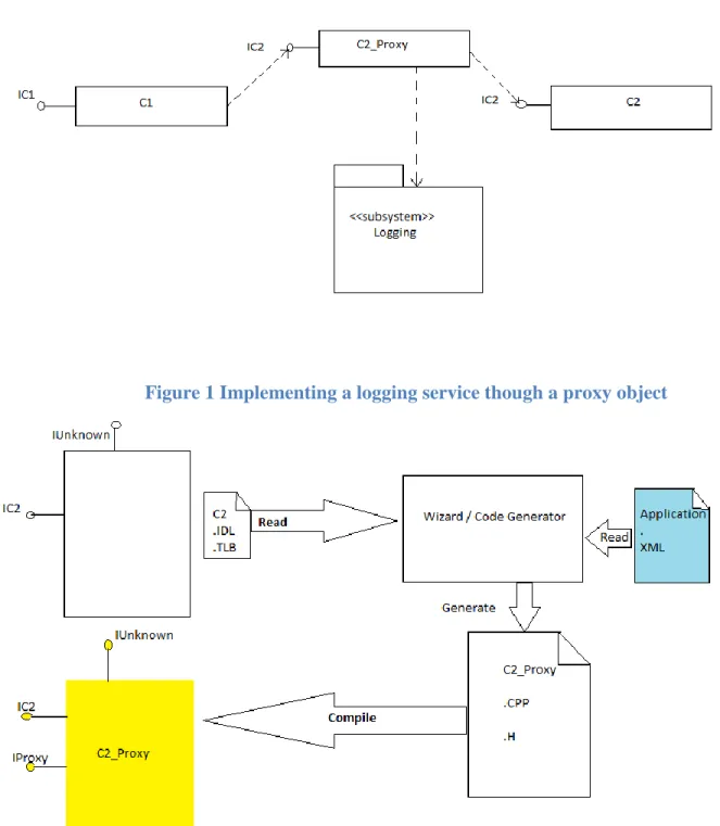
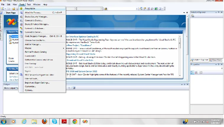
Use of a proxy object is described with the help of an UML class diagram, given in Fig. 1. In the diagram, C2 implements the interface IC2 for which we are going to provide the logging service. This is carried out by creating a proxy (C2_Proxy) which implements the same interface as of C2. This proxy which now provides the logging service is placed between the client and the C2. The proxy indeed forwards all the invocations to the corresponding operations in C2. The generation of the proxy object (C2_Proxy) is illustrated in Fig. 2. When the source code for the proxy object is generated, the additional services are implemented by intercepting the method calls to the COM objects. The component specification is given as input to the code generator, as well as the specification of the desired services. Component specification is given to the code generator in the form of an IDL file or Type Library file. Whereas, the specification of services could be XML based format or in the graphical user interface of the add-in application. The code generator uses these information to generate a set of files, which in turn is compiled to give
18
the proxy object.
Figure 1 Implementing a logging service though a proxy object
19
4. Implementation of Visual Studio Add-in
Usage of Smart Devices has increased in the recent years. As a result, there are wide ranges of software available in the market for the development of applications for these Smart Devices. Microsoft Visual Studio provides in-build support for such software development in smart devices such as Pocket PCs and Smart Phones [14]. The major advantage of using Visual Studio for Smart Device development is that, we could use any of the programming languages such as Visual C#, Visual Basic or VC++ for developing such applications. Another advantage is that, Smart Device applications can be developed in the same way as any other desktop applications, while using Visual Studio. Visual Studio also has some project templates for developing Smart Devices applications. The developers can select their template of interest and then start coding on the top of those templates. The emulators provided by the Visual Studio helps to run and debug the code, as like testing any other desktop application.
4.1. Visual Studio
Visual Studio is an IDE developed by Microsoft, which provides a convenient environment for Microsoft’s Visual Programming Language. It mainly supports most of the Microsoft’s Console and Graphical User Interface (GUI) applications. The GUI applications include Windows Forms application, Web application, Web services Application, Smart Device Applications etc. This IDE supports all windows platforms like Microsoft Windows, Windows CE, Windows Mobile and .Net. Programming languages like Visual Basic, VC++, C, C++ and C# are also supported by Visual Studio. Apart from these features, it also provides different kinds of additional support like Code Editor, Debugger, Designer and Extensibility.
4.1.1. Extensibility
Extensibility is the phenomenon by with the scope of a software system is extended by adding additional functionality to it. In case of Visual Studio, Extensibility is the way by which the functionality of the IDE is extended by adding some additional functionality. This is done by the creation of Add-ins for Visual Studio, with the help of Add-in wizards. Once the Add-in is developed and compiled, it then becomes the part of the Visual Studio itself.
20
4.1.2. Visual Studio Add-Ins
A Visual Studio Add-in is a pre-compiled DLL, which runs inside a Visual Studio IDE [15]. Users of Visual Studio are allowed to extend the functionalities of Visual Studio IDE by creating the own custom Add-in. Add-ins are manually created using Visual Studio Add-in wizards for generating Add-Ins from a pre-defined templates. The wizard creates Add-In projects, which can be readily customized to develop custom Add-ins. This custom Add-ins is then compiled and the main IDE loads it as a DLL [3].
4.2. User Manual for Add-In
The following Figure-3 shows the Visual Studio IDE with the add-in named “ProxyAddin”. This add-in is present in the “Tools” menu of the IDE. In order to launch the add-in, click on the “Tools” menu and it will show the “ProxyAddin”, that is the add-in created for entire process of proxy object code generation with this visual studio add-ins. This will open a windows form as shown in Figure-4.
21
Figure 3 Visual Studio Add-in
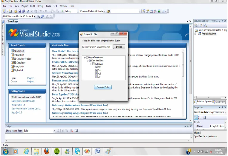
Figure-4 shows the dialog “Browse DLL File”, which is responsible for loading the original component. The original Smart Device Component which is a DLL file is browsed using the “Browse” button. As soon as the DLL file is browsed in the dialog, the dialog given in the Figure-5 is shown.
22
Figure 4 DLL Browser
Figure-3 shows the “New Proxy Project Wizard” dialog. There are two text boxes in the wizard. One is the textbox for the name of the target proxy project and the other one is the location of the proxy project. The name needs to be entered manually and the location can be either entered manually or browsed by using the “Browse Project Location” button. This wizard creates a new project in the specified location, with the specified name. Once the “Create Proxy” button is pressed after giving the “Project Name” and “Project Location” inputs, the new project is created. Then the message box with text “Proxy Project Successfully Created and Loaded” is displayed as shown in the Figure-6. This means that the project is created as well as loaded in the solution, so as to help the code generator to generate the code in the created project.
23
Figure 5 New Proxy Project Wizard
Figure-5 shows the dialog which is shown after the proxy is created and loaded. In this state, the user is supposed to give input to the code generator by selecting the method for which the logging service to be included in the generated code. In the dialog, the “Original Component” check box represents the content of the original component. The check box with “Class” suffix represents the classes. The check boxes with “I” prefix represents the interfaces and the rest of the check boxes represents the methods. If the user wants to add service to any of these elements, they are supposed to select the respective check box. For instance, the user can select the “Original Component” check box, if he/she wants to provide service for the entire component as whole. But in the example, only the methods and the class check boxes are checked. This means that the user is interested in adding service only to these items.
24
25
Figure 7 Select Methods
Once the methods are selected in the Figure-7, the user is supposed to press the “Generate Code” button. As soon as the “Generate Code” button is pressed, the proxy is generated. Figure-8 shows that “Proxy Code Generated Successfully”, which means that the proxy Smart Device Project has been created and it is shown in Figure-9.
26
27
Figure 9 Created Proxy Project
4.3. Example Component
In order to represent the original component we created a smart device component “Calculator”, which performs the basic operations of a calculator like addition, subtraction, multiplication and division. This component has the interface by name “ICalculator”, through which it provides these method implementations. The methods are namely “Add”, “Sub”, “Mul” and “Div”, which represents addition, subtraction, multiplication and division respectively. This component is represented by the header file “Calculator.h” and class file “Calculator.cpp” in the Appendix. The file “Calculator.h” declares the methods “Add”, “Sub”, “Mul” and “Div”, which are defined
28
in the file “Calculator.cpp”. This component is then given as input to the code generator, where the proxy component is generated. The generated proxy component’s header file and class file corresponding to the original component’s files are also given in the Appendix example “Calculatorproxy.h” and “Calculatorproxy.cpp”. The generated proxy header file “Calculatorproxy.h” declares the methods “Add”, “Sub”, “Mul” and “Div” in the same way as that of the original header file. But the proxy class file “Calculatorproxy.cpp” instead of implementing the methods, it adds the logging service to the method and forwards the corresponding method in the original component itself.
29
5. Code Generator
In this thesis work, proxy components are generated by using the Code Generator specially developed for generating the proxy code. This Code Generator gets the required information from the original component and generates the proxy component with added real-time services. The Code Generator uses the Microsoft Visual Studio VCCodeModel namespace for generating C++ Code Model, which in turn builds the proxy component. VCCodeModel Namespace provides interfaces such as VCCodeModel, VCCodeElement, VCCodeFunction, etc. The following sections explain how the proxy component is generated with the help of these interfaces.
5.1. Smart Device Project
Visual Studio Smart Device Components are usually generated in the Smart Device Projects. These Projects are then compiled to get the Smart Device Component. In order to generate the proxy component, a proxy project should be created. Visual Studio Automation Object Model provides the interface named DTE for the generation of Solutions and Projects. The code shown in [Code 1] shows how a Visual Studio Solution and Visual Projects are created using the DTE Interface. As soon as it is created, the Smart Device Project is then loaded from the disk to the Visual Studio IDE as the current project. When the project is loaded, the project elements are generated on top of this project, with the help of VCCodeModel interface. VCCodeModel interface helps in adding project elements like classes, header files, resource files, etc. to the project. The following code [Code 2] explains how a VCCodeModel object helps in the creation the VC++ class, header file, etc.
30
DTE dte = new DTE();
Solution solution = new Solution(); solution = dte.Solution;
solution.Create(solution_location,solution_name);
Project project = new Project();
project = solution.AddFromTemplate("ProxyProject",project_location, project_type, true);
solution.SaveAs(solution_location + "\\" + solution_name + ".sln");
Code 1: Using DTE Interface for VC++ Solution and Project generation.
5.2. VC++ Source Code generation
VC++ class and VC++ header files are generated by the help of the interface VCCodeElement, which is shown in the code example [Code 2]. VCCodeElement object, which is created as a VC++ file can be used to generate a fully functional C++ class source file. The code [Code 2] also describes how the C++ class member elements are created inside a VC++ class file programmatically.
VCCodeModel codeModel = (VCCodeModel)application.Solution.Item(1).CodeModel;
VCCodeElement vcClass = ((VCCodeElement)(
codeModel.AddClass("C" +name, className + ".cpp", 0, null, null, vsCMAccess.vsCMAccessDefault)));
VCCodeElement vcHeader = ((Microsoft.VisualStudio.VCCodeModel.VCCodeClass)( codeModel.AddClass(headerName, location, 0, pclass, null, EnvDTE.vsCMAccess.vsCMAccessDefault)));
VCCodeFunction function=(VCCodeFunction)vheader.AddFunction(cname,
vsCMFunction .vsCMFunctionConstructor, "", 0, vsCMAccess.vsCMAccessPublic, location);
VCCodeInclude include=codeModel.AddInclude(hname,location, 0);
VCCodeMapEntry comMapEntry=comMap.AddEntry("COM_INTERFACE_ENTRY", -1); comMapEntry.AddParameter(iname,-1);
VCCodeParameter
codeParam=(VCCodeParameter)vcCodeElement.AddParameter(parameterDeclarationLis t[j], parameterTypeDeclarationList[j], 0);
31
Code 2: Using VCCodeModel Namespace for VC++ Code Generation.
5.3. Generated Code
In order to provide a good understanding of the code generation process, the original component and the proxy component files are given in the Appendix section. Appendix-A represents the original component’s C++ header file “Calculator.h”, where the COM class is declared. Appendix-B represents the original component’s C++ class file “CCalculator”, which implements the original component’s COM class by defining the methods namely Add, Sub, Mul and Div. Appendix-C represents the original component’s IDL file, which defines the interface “ICalculator”. Appendix-D, E and F are the generated proxies for the proxy component, which corresponds to Appendix-A, B and C files respectively. The C++ class “CCalculatorproxy” [Appendix-E] implements the proxy component’s COM class by implementing the same methods as that of the original component. The implementation is done by adding the services requested by the user to the method and forwarding the method call to the corresponding method in the original component itself. Thus, the proxy method implementation does not change the functionality of the original methods, but only adds additional services to it. This C++ class gets access to the original component’s method through the member variable “proxy” which is of type “ICalculator”. The member variable “proxy” is declared in the header file [Appendix-D], which imports the original component’s interface “ICalculator” using the import (#import) Directive. Even though, the proxy component has its own COM Class implementation, it refers to the same interface “ICalculator”, which is the interface of the original component. The proxy component refers to the original component’s interface through the IDL file [Appendix-F], which incorporates the “ICalculator” interface of the Original Component by incorporating the original component using the import (importlib) statement.
32
5.4. Discussion
The Code Generator developed in our thesis work follows a similar approach to that of the Code Generator developed by Manzoor Ahmed [4] and Saud Ur Rehman [6]. But both of them have their own limitations. In the work of Manzoor Ahmed [4], C# code is generated. The major drawback of the generated C# code is that, it requires .Net compact framework for its building the generated proxy component. This problem can only solved by generating code, which does not require .Net Compact Framework for building. Generating C++ code instead of C# code is the only possible solution for this problem. This major problem has been successfully solved in our Code Generator by generating C++ code. Irrespective of the original component, C++ code is generated, which does not require .Net Compact Framework. In the work of Saud Ur Rehman [6], VC++ code is generated, which is similar to the code which is generated in our thesis work. Even though our Code Generator uses a similar approach in the generation of the VC++ code, it has its own limitations which limit the scope of the generated code. These limitations are discussed below.
1. The code generated failed to generate VC++ class elements programmatically. Instead, the elements of the VC++ class elements like variables, functions, etc. are directly written to the source file statically. The Code Generated developed by us overcomes this situation by generated VC++ elements by creating the VC++ class elements programmatically as discussed in Section 5.2.
2. COM related code is not generated automatically by the use of Visual Studio Automation. Rather, they used static injection of COM related code into the proxy. This limitation has been overcome in our thesis work by using VCCodeIDLLibrary Interface for generating COM related code.
3. Static injection of the UUID of the original component into the proxy component is also another notable limitation. This limitation has been overcome in our thesis by the dynamic injection of UUID into the proxy component.
33
6. Conclusion and Future Work
Component based development plays an important role in today’s software field. They have their own set of principles and methodologies, prescribed by their own Component Models. These components models are emerging over years to new technologies and to overcome the limitations of the older ones. In most of the cases, these technologies are adopting to support Real Time Systems. This problem is due to the complexity in case of the Real Time Systems such as their small size, time constraints, CPU, memory etc… So, in order to meet these constrains, the Component model should be tailored in a way that they consider all the limitations of any Real Time Systems. For this reason, Component Models are evolving over time to support Component Based Development in Real Time Systems. Although these Component Models evolve over time, there is not any perfect Component Model to support Real Time Systems development. But they are evolving over time and become powerful in their new versions.
This thesis work is a step forward for the development of the application of Component Based Development in Real Time Embedded Systems.
In this thesis work, an existing smart device component has been inspected and a real-time service is added to it. This is accomplished by creating a visual studio add-in, which inspects the original component and gets the specification of the existing component’s specification through its user interface. The user interface then displays the methods present in the existing component to the user, where the user selects the method for which the logging service is to be added. After the selection of method is done, the add-in generates the proxy project. The proxy project is then compiled to get the proxy component, which implements the same interface as that of the original component. The proxy component lies between the client and the original component, where it eventually forwards the method call from the client to the corresponding method in the original component. At the same time it also adds the logging service the selected methods.
34
The proxy generated in this thesis work, adds a logging service to the original component. But it would be quite interesting to extend this functionality by adding some other services like synchronization and execution time measurement, mentioned in Section-3.5. The future work of this thesis is to implement Synchronization and Execution Time Measurement, in the same way as the Logging service. When these additional services are implemented, the users are then able to select their own service of interest to include it in the generated proxy.
35
7. References
[1] Ivica Crnkovic, Magnus Larsson “Building reliable Component-based Software Systems”, Artech House Inc., (2002. pp 3-4).
[2] Frank Luders, “An Evolutionary Approach to Software Components in Embedded Real-Time Systems”, Department of Computer Science and Electronics, Mälardalen University, 2006.
http://www.mrtc.mdh.se/publications/1219.pdf
[3] Jeffery Cogswell, “Developing Visual Studio .NET and Macros and Add-In” Wiley Publishing Inc., (2003. pp. 117-118).
[4] Manzoor Ahmad, “A Code Generator for Component based Software Services in Smart Devices”, Master Thesis, Mälardalen University, Sweden, 2010.
http://mdh.diva-portal.org/smash/record.jsf?pid=diva2:372251 [5] G. Pour, “Component-Based Software Development Approach: New
opportunities and Challenges,” Proceedings Technology of Object-Oriented Languages, 1998. TOOLS 26... pp. 375-383.
[6] Saur Ur Rehman, “A Visual Studio Add-In for Software Component Services in Smart Devices “, Master Thesis, Mälardalen University, Sweden, 2011.
http://mdh.diva-portal.org/smash/record.jsf?searchId=1&pid=diva2:414567 [7] Box, D., Essential COM, Reading, MA: Addison-Wesley, 1998.
[8] Bill Councill, George T. Heineman, “Definition of a software component and its elements”. Addison-Wesley Longman Publishing Co., Inc. Boston, MA, USA 2001.
[9] MSDN, “Component Object Model”.
36
[10] David E.Simon, “An Embedded Software Primer”, Addison-Wesley Professional, 1999
[11] Anders Möller, Mikael Åkerholm, Johan Fredriksson and Mikael Nolin, “Software Component Technologies for Real-Time Systems-An Industrial Perspective”, MRTC, Malardalen University, Sweden
[12] MSDN, “Microsoft Visual Studio VCCodeModel Namespace”,
http://msdn.microsoft.com/en-us/library/microsoft.visualstudio.vccodemodel.aspx [Accessed 12 Jan 2012].
[13] MSDN, “Microsoft Visual Studio VCCodeElement Namespace” ,
http://msdn.microsoft.com/en-us/library/microsoft.visualstudio.vccodemodel.vccodeelement.aspx[Accessed 12 Jan 2012].
[14] MSDN, “Smart Device Development”, http://msdn.microsoft.com/en-us/library/sa69he4t(v=vs.80).aspx [Accessed 22 Dec 2010]
[15] MSDN, “Creating Add-Ins and wizards”, http://msdn.microsoft.com/en-us/library/5abkeks7(v=vs.80).aspx [Accessed 22 Dec 2010]
37
Appendix
A. Original Component Header File
// Calculator.h : Declaration of the CCalculator #pragma once #ifdef STANDARDSHELL_UI_MODEL #include "resource.h" #endif #ifdef POCKETPC2003_UI_MODEL #include "resourceppc.h" #endif #ifdef SMARTPHONE2003_UI_MODEL #include "resourcesp.h" #endif #ifdef AYGSHELL_UI_MODEL #include "resourceayg.h" #endif #include "SDCalculator.h" // CCalculator
class ATL_NO_VTABLE CCalculator :
public CComObjectRootEx<CComMultiThreadModel>, public CComCoClass<CCalculator, &CLSID_Calculator>, public ICalculator { public: CCalculator() { } #ifndef _CE_DCOM DECLARE_REGISTRY_RESOURCEID(IDR_CALCULATOR) #endif
38 BEGIN_COM_MAP(CCalculator) COM_INTERFACE_ENTRY(ICalculator) END_COM_MAP() DECLARE_PROTECT_FINAL_CONSTRUCT() HRESULT FinalConstruct() { return S_OK; } void FinalRelease() { } public:
STDMETHOD(Add)(SHORT firstValue, SHORT secondValue, SHORT* returnValue); STDMETHOD(Sub)(SHORT firstValue, SHORT secondValue, SHORT* returnValue); STDMETHOD(Mul)(SHORT firstValue, SHORT secondValue, SHORT* returnValue); STDMETHOD(Div)(SHORT firstValue, SHORT secondValue, SHORT* returnValue); };
OBJECT_ENTRY_AUTO(__uuidof(Calculator), CCalculator)
B. Original Component CPP File
// Calculator.cpp : Implementation of CCalculator #include "stdafx.h"
#include "Calculator.h"
// CCalculator
STDMETHODIMP CCalculator::Add(SHORT firstValue, SHORT secondValue, SHORT* returnValue) { *returnValue = firstValue+secondValue; return S_OK; }
39
STDMETHODIMP CCalculator::Sub(SHORT firstValue, SHORT secondValue, SHORT* returnValue) { *returnValue = firstValue-secondValue; return S_OK; }
STDMETHODIMP CCalculator::Mul(SHORT firstValue, SHORT secondValue, SHORT* returnValue) { *returnValue = firstValue*secondValue; return S_OK; }
STDMETHODIMP CCalculator::Div(SHORT firstValue, SHORT secondValue, SHORT* returnValue) { *returnValue = firstValue/secondValue; return S_OK; }
C. Original IDL File
// SDCalculator.idl : IDL source for SDCalculator //
// This file will be processed by the MIDL tool to
// produce the type library (SDCalculator.tlb) and marshalling code. import "oaidl.idl"; import "ocidl.idl"; [ object, uuid(DDDE3191-3684-4EEE-9A73-ADCE2072558E), helpstring("ICalculator Interface"), pointer_default(unique) ]
40
[helpstring("method Add")] HRESULT Add([in] SHORT firstValue, [in] SHORT secondValue, [out,retval] SHORT* returnValue);
[helpstring("method Sub")] HRESULT Sub([in] SHORT firstValue, [in] SHORT secondValue, [out,retval] SHORT* returnValue);
[helpstring("method Mul")] HRESULT Mul([in] SHORT firstValue, [in] SHORT secondValue, [out,retval] SHORT* returnValue);
[helpstring("method Div")] HRESULT Div([in] SHORT firstValue, [in] SHORT secondValue, [out,retval] SHORT* returnValue);
}; [
uuid(22A0DB55-585B-46FC-9DE7-74016140FA87), version(1.0),
helpstring("SDCalculator 1.0 Type Library") ] library SDCalculatorLib { importlib("stdole2.tlb"); interface IDocHostUIHandlerDispatch; interface IAxWinAmbientDispatchEx; [ uuid(D680982C-D211-4431-85D8-64963A2DDCB4), helpstring("Calculator Class") ] coclass Calculator {
[default] interface ICalculator; };
};
D. Generated Header File
#pragma once
#include "ProxyCalculator.h"
#import "C:\Users\anand\Downloads\Gopal_Thesis\gtl09001\MyAddin\Gopal_Thesis\New Version\SDCalculator.dll" no_namespace raw_interfaces_only
class CCalculatorproxy :
public CComObjectRootEx<CComMultiThreadModel>,
public CComCoClass<CCalculatorproxy, &CLSID_Calculatorproxy>, public ICalculator
{ public:
CCalculatorproxy(void);
41 COM_INTERFACE_ENTRY(ICalculator) END_COM_MAP() #ifndef _CE_DCOM DECLARE_REGISTRY_RESOURCEID(IDR_CALCULATORPROXY) #endif HRESULT FinalConstruct() {
HRESULT hr = CoCreateInstance(__uuidof(Calculator), NULL,
CLSCTX_INPROC_SERVER, __uuidof(ICalculator),(void**) &proxy); return hr;
} private:
ICalculator *proxy;
public:
STDMETHOD (Add) (SHORT firstValue,SHORT secondValue, SHORT* returnValue);
public:
STDMETHOD (Sub) (SHORT firstValue,SHORT secondValue, SHORT* returnValue);
public:
STDMETHOD (Mul) (SHORT firstValue,SHORT secondValue, SHORT* returnValue);
public:
STDMETHOD (Div) (SHORT firstValue,SHORT secondValue, SHORT* returnValue); }; OBJECT_ENTRY_AUTO(__uuidof(Calculatorproxy), CCalculatorproxy) CCalculatorproxy::CCalculatorproxy(void) { }
E. Generated CPP File
#include "StdAfx.h" #include "Calculatorproxy.h"42
#include "atltime.h" #include "fstream"
STDMETHODIMP CCalculatorproxy::Add(SHORT firstValue, SHORT secondValue, SHORT* returnValue)
{
HRESULT hr;
CTime startTime = CTime::GetCurrentTime();
hr=proxy->Add(firstValue,secondValue, returnValue); CTime endTime = CTime::GetCurrentTime();
CTimeSpan diffTime=endTime-startTime; char str[128];
sprintf(str,"%p",diffTime.GetSeconds()); CTime time = CTime::GetCurrentTime(); std::ofstream myfile;
myfile.open ("ExecutionTime.txt");
myfile<<time.GetHour()<<"::"<<time.GetMinute()<<"::"<<time.GetSecond()<<":"; myfile <<"Method Add is executed in"<<str<<"Seconds";
myfile.close(); return hr;}
STDMETHODIMP CCalculatorproxy::Sub(SHORT firstValue, SHORT secondValue, SHORT* returnValue)
{
HRESULT hr;
CTime startTime = CTime::GetCurrentTime();
hr=proxy->Sub(firstValue,secondValue, returnValue); CTime endTime = CTime::GetCurrentTime();
CTimeSpan diffTime=endTime-startTime; char str[128];
sprintf(str,"%p",diffTime.GetSeconds()); CTime time = CTime::GetCurrentTime(); std::ofstream myfile;
myfile.open ("ExecutionTime.txt");
myfile<<time.GetHour()<<"::"<<time.GetMinute()<<"::"<<time.GetSecond()<<":"; myfile <<"Method Sub is executed in"<<str<<"Seconds";
myfile.close(); return hr;}
STDMETHODIMP CCalculatorproxy::Mul(SHORT firstValue, SHORT secondValue, SHORT* returnValue)
43
HRESULT hr;
CTime startTime = CTime::GetCurrentTime();
hr=proxy->Mul(firstValue,secondValue, returnValue); CTime endTime = CTime::GetCurrentTime();
CTimeSpan diffTime=endTime-startTime; char str[128];
sprintf(str,"%p",diffTime.GetSeconds()); CTime time = CTime::GetCurrentTime(); std::ofstream myfile;
myfile.open ("ExecutionTime.txt");
myfile<<time.GetHour()<<"::"<<time.GetMinute()<<"::"<<time.GetSecond()<<":"; myfile <<"Method Mul is executed in"<<str<<"Seconds";
myfile.close(); return hr;}
STDMETHODIMP CCalculatorproxy::Div(SHORT firstValue, SHORT secondValue, SHORT* returnValue)
{
HRESULT hr;
CTime startTime = CTime::GetCurrentTime();
hr=proxy->Div(firstValue,secondValue, returnValue); CTime endTime = CTime::GetCurrentTime();
CTimeSpan diffTime=endTime-startTime; char str[128];
sprintf(str,"%p",diffTime.GetSeconds()); CTime time = CTime::GetCurrentTime(); std::ofstream myfile;
myfile.open ("ExecutionTime.txt");
myfile<<time.GetHour()<<"::"<<time.GetMinute()<<"::"<<time.GetSecond()<<":"; myfile <<"Method Div is executed in"<<str<<"Seconds";
myfile.close(); return hr;}
F. Generated IDL File
// Proxy.idl : IDL source for Proxy //
// This file will be processed by the MIDL tool to
44 import "oaidl.idl"; import "ocidl.idl"; [ uuid(5E2E2072-88D1-4DC4-B617-CAE19E93A21B), version(1.0),
helpstring("Proxy 1.0 Type Library") ] library ProxyLib { importlib("stdole2.tlb"); importlib("C:\Users\anand\Downloads\Gopal_Thesis\gtl09001\MyAddin\Gopal_Thesis\ New Version\SDCalculator.dll "); interface IDocHostUIHandlerDispatch; interface IAxWinAmbientDispatchEx; [ uuid(f09a1273-9ff3-4c4d-b5d6-83c03a9b4445), helpstring("Calculatorproxy Class") ] coclass Calculatorproxy {
[default] interface ICalculator; };};