Analyzing Unidentified
lock~d·Joint
Failures in
Kinematically Redondant
Manipulators
e. • • • e. • • • • • • • • • • • ••
•
• • • • •
•
• • • •
•
•
Manish Goel*School of Electrical and Computer Engineering Purdue University
West Lafayette, Indiana 47907-1285 Anthony A. Maciejewski t
Electrical and Computer Engineering Department Colorado State University
Fort Collins, Colorado 80523-1373 e-mail: aam@engr.colostate.edu
Venkataramanan Balakrishnan
School of Electrical and Computer Engineering Purdue University
West Lafayette, Indiana 47907-1285
Received 30 Jury 2003; accepted 2 Ausus! 2004
Robots are frequently used for operations in hostile environments. The very nature of these environments, however, increases the likelihood of robot failures. Common failure-tolerance techniques rely on effective failure detection and identification. Since a failure may not always be successfully identified, or, evenifidentified, may not be identified soon enough,itbecomes important to consider the behavior of manipulatorswith
uni-dentified failures. This work investigates the behavior of robots experiencing uniuni-dentified locked-joint failures in a general class of tasks characterized by point-to-point motion. Based on the analysis, a procedure for workspace evaluationisdeveloped that allows for the identification of regionsinthe manipulator's workspace in which tasks may be com-pleted even with such failures. ©2005 Wiley Periodicals, Inc.
"Presently at Applied Materials, Santa Clara, California 95050 "Ib whom all correspondence should be addressed.
JournalofRobotic Systems 22(1), 15-29 (2005) ©2005 Wiley Periodicals, Inc.
2. MATHEMATICAL FRAMEWORK
ZHenceforththe term "position" will be used to mean any combi-nation of position and/or orientation variables.
(2) (1) x~f(q).
where xe R" is the position of the end effector, q
eRnis the vector of joint variables, and m and n the
dimensions of the task space and joint space, teepee-tively. Manipulators that have more degrees of
free-dom (DOFs)thanrequired for a task, i.e., n>m, are
said to be redundant. 'The end-effector velocity is ex-pressed in terms of the joint rates as
where]EHm X n is the manipulator Jacobian,
x
is theend-effector velocity, and
it
is the joint velocity.Ifperfect servo control of the joints is assumed,
then in a healthy manipulator the actual joint velod-failed, the ability of manipulators to converge to de-sired end-effector positions even with imperfect/ approximated lacobtana/Iacobian-inverses has been
addressed in refs.26 and27.Therefore, we focus on
the other case where a joint has actually locked, but the controller continues to command motion of that joint as though it were healthy. For a general class of tasks characterized by point-to-point motion, we ex-amine convergence issues such as whether the
ma-nipulator comes to rest and,ifso, whatisthe terminal
position and orientation of the end-effector. The con-vergence analysis is restricted to purely kinematic ef-fects, due to the fact that the dynamic effects of a
fail-ure are essentially transient in nature and do not
significantly affect the convergence behavior.18.28-3 0
Conditions under which the manipulator converges are explicitly defined and the anomalies in behavior
due to the faults explained and illustrated with
ex-amples. These conditions are used to evaluate the convergence behavior of the manipulator over the postfailure workspace. This allows for the identifica-tion of workspace regions for which task compleidentifica-tion may be possible even with unidentified failures.
The position and orientation- of the end effector of a manipulator can be expressed in terms of its joint variables by the kinematic equation
"nus
assumes a typical commercial robot where duplicate sensing and/or analytical redundancy does not exist.1. INTRODUCTION
16 • Journal of Robotic Systems-200S
Failures in robots occur frequently in industrial operations.' The likelihood of failures is far greater when robots are operated in harsh environments.e
Since the control of the individual jointsisessentially
independent in a typical robotic system, most failures affect only a single joint. While there are several ways in which a robot may fail,3--7 one common failure mode is a "locked joint," where the affected joint's ve-locity is identically zero. Such a failure may have catastrophic consequences or, at the very least, stg-nificantly degrade the system performance.
Since immediate human attention for repair or re-covery is often not practical in hostile environments, it is desirable that the robot itself be able to cope with failures. A common approach to enhancing failure
tolerance capability in a robotisthe incorporation of
redundancy in the design. This may be in the form of duplicated components" or through the intelligent utilization of kinematic redundancy.9-13 Though there has been considerable work in the area of failure tol-erant systems, there remain Significant questions about the postfault behavior of robotic systems that do not incorporate fail-safe mechanisms. Existing failure tolerance schemes rely on effective failure de-tection and identification}4-16 only after a failure is identified is an appropriate failure recovery strategy
initiated.17-21However, failure identification is itself a
difficult process that may not alwaysbesuccessful.W
While it is easy to envision a failure recovery strategy for identified failures, the situation is much
more difficult when a failure is merely detected, but
not identified.Inparticular, consider a joint
malfunc-tion where a Significant deviamalfunc-tionisdetected between
the commanded joint velocities and those returned by the joint sensors. Identifying whether this malfunc-tion is due to a joint locking up or whether the sensor
is(erroneously) returning a constant joint position is
not possible.' A simple response to such a situation is
to implicitly assume that a jointhaslocked, and to
ad-justthecontrol law accordingly so as to not command
motion of the joint in questicn.P However, given that sensor failures are more likely than joint actuation failures,22 this may not be the best course of action, as the work;race is unnecessarily reduced (often quite
severely'f ,25).
We therefore consider the scenario where the con-trol Iaw remains unmodified, and explore the conse-quences. For the case when the sensor has indeed
Gael et: al.: Analyzing Unidentified Locked-joint Failures in Kinematically Redundant Manipulators • 17
ties
'Ia
equal the commanded velocities'Ic'
However,inthe event of a locked-joint failure of theith joint, the
corresponding element of
'Ia
is identically zero. Then,the actual end-effector velocity is given by
(3)
where
iJ
is the post-failure Jacobian, given byi/=[h ...
jl-l 0 ji+l ... jll]. (4)know whether the end effector will eventually
con-verge toit.3
The first question that arisesinthe study of
con-vergence behaviors of a failed manipulator is
whether the desired task position is reachable, that is,
lies within the postfeilure workspace. If indeed it
does, the issue of whether, under the employed con-trol scheme, the manipulator converges correctly to
the desired position must be examined. Evenif
reach-ability of the desired position is not possible for a cer-tain failure, it may still be of interest to know whether the control allows the failed manipulator to converge to the position closest to that desired.
A common method for generating
'I
is the inversekinematic scheme
where x,isthe actual position of the end effector, and
Ke is a constant position error gain that is adjusted when necessary to limit the commanded end-effector velocity to a maximum allowable value.
In the event of a locked-joint failure, the actual end-effector velocity in general will not be as
com-manded by (6). In particular,ifjoint
i
fails, the actualend-effector velocity is given by
where G is a generalized inverse of
J
satisfying thePenrose condition
J
GJ= ]. A frequently encounteredgeneralized inverse is the pseudomverse
r.
whichyields the least squares minimum norm solution. For
full rank
J,
the pseudoinverse can be expressed asr~JT(Jf)-l.
Inthis work, a general class of tasks characterized
by sequences of point-to-point moves is considered. The commanded end-effector velocity is simply straight line motion towards the desired task position xci:
The workspace of a manipulator,ingeneral, reduces
after it experiences a failure.9,24,2S However, under
certain conditions, a task position can be guaranteed to be reachable by a redundant manipulator after an arbitrary joint failure along a trajectory. This is achieved by ensuring that the ranges of the joint val-ues along the nominal trajectory never exceed the bounds of the joint values given by the self-motion manifold(s) of the desired task positionj"
The bounds of the self-motion manifolds can be directly computed by numerically tracing the mani-foldfs}. Another more efficient way is to note that the extremal values of a joint variable are determined by the hyperplane that is tangential to the self-motion manifold with a normal that is collinear with the cor-responding axis in the joint space. Consequently, the contribution of that joint to the null motion of the
ma-nipulator is identically zero. Itis easily shown that a
jointihas a zero contribution to the null motion of the
manipulator if and only if the Jacobian
IJ
<lii ...
ji-lOji+l ...jn]is rank deficient4p
Ifthecon-dition for a joint to be at an extremumisnot satisfied
for any configuration corresponding to the desired end-effector position, then the range of that joint on
the manifold is unconstrained,i.e.,it spans the entire
[0° 360°] range. The limiting values of the range of joint i are thus obtained by simultaneously solving the following equations:
3. POST·FAILURE REACHABILITY (6) (5)
'I=Gx,
(8) (7)which can be obtained by combining (3), (5), and (6).
Although
x
a may not drive the end effector directlytowards the desired task position, it is of interest to
3A manipulator is considered to have converged when all its joints come to rest,i.e.,alljoints, except possibly the failed joint, arecommanded a zero velocity by the employed control scheme. "The rank deficiency of this matrix is referred to as a
II
18 • Journal of Robotic Systems-200S
and
nr(i)=o,
,
j=l,,,.,n-m, (9)izing erroneous convergence of a manipulator, it is necessary to identify conditions under which only the failed joints of the manipulator are commanded mo-tion.
i
I !i :11' I where {nh, ... ,nJn_ ) represent anyn-m linearly
in-dependent null vectors of
J.
The identified extrema partition the [0° 360°] ranges of the joints into a number of segments. The
segments corresponding to the joint ranges of the
self-motion manifolds can then be identifiedby
test-ing the midpoint of each of the obtained segments.
Though this technique is a general one, its applica-bility depends upon the ease with which (8) and (9) can be solved.
The above technique presents an efficient means for evaluating the effect of a given control scheme on the post£ailure reachability of a task position. More-over, the technique can also be employed for the de-sign of control strategies to guarantee the reachability
of critical task positions in a manipulator's
workspace."
4. ANALYZING CONVERGENCE BEHAVIORS
Independently of whether or not the reachability of a
task position is guaranteed for a failure, itis
fmpor-tant to analyze the convergence behavior of a failed
manipulator for a given control scheme.Ifthe desired
task position is reachable, will the failed manipulator
converge to that position?Ifitis not reachable, will
the failed manipulator converge to the closest
pos-sible position?Ifit does not converge to one of these
positions, to what position does it converge,ifit does
converge at all? These issues form the crux of the analysis of the postfault behavior of manipulators.
We will define "convergence" formally to mean.
that the joints come to rest, thatis,
qa
=O.
This ispos-sible for a failed manipulatorifeither all its joints are
commanded zero velocities, or if only the failed
joint(s) are commanded motion (since
qa=ilqJ.
Inthe context of the defined control framework, conver-gence with zero velocities of all the manipulator
jointsispossible only if the commanded end-effector
velocity is zero. Since a zero end-effector velocity is
commanded onlyifthe end effectorisat the desired
position, convergence with
qc=
0 implies correctcon-vergence. Convergence with
qc"'O
(i.e., when someor all of the failed joints are commanded nonzero
ve-locities), therefore, must imply
"erroneous-convergence" or convergence to a position other than the desired one. To determine the factors
character-4.1. Characterizing Convergence
The following theorem shows that a manipulator gets "stuck," or converges with a non-zero commanded velocity, only when the following two conditions hold:
• The commanded end-effector velocity lies in the space spanned by the failed columns of the Jacobian.
• The post-failure weighted Jacobian is rank de-ficient.
This result is derived as follows:
Theorem 1:Consider a manipulator at a nonsin-gular configuration, driven by a generalized inverse control
(10)
where G=w-1f(Jw-1JT)-1 for some symmetric
W>O.5Let S be the set of the indices of the klocked
joints, and letjiandWidenote theith columns of
J
andW, respectively. Then,
1.Only the failed joints are commanded motion
if and onlyif the commanded end-effector velocity
vector
Xc
lies in the space spanned by the columnscorresponding to the failed joints of the Jacobian,i.e.,
for some a;EIR, iES, where e, represents a natural
basis vector.
2. Moreover, the failed joints are commanded
nonzero velocities onlyifa postfailure weighted
Jaco-bian is rank deficient, i.e.,
(12)
5'rhe matrix W is used to specify the relative weighting on the joint velocities when determining the minimum norm solution.
Goel et al.: Analyzing Unidentified Locked-loint Failures in Kinematically Redundant Manipulators • 19
where i(JW-1)E11{lfIx{n-k)is obtained from
JVV-
1 by zeroing the columns with indices i Es.
Proof
1. The condition
can be established simply by premultiplymg the equation on the left by
J.
For the converse the following is given:
LetN ER(n-m)xnbe a matrix whose columns span the
null space of
J.
Then, for the given inverse controlUsing the fact that
x
c=J
qCf the two equations above can be writtenina matrix form asThe matrix on the left is full-rank and invertible and so the system of equations has a unique solution. Since qc=Li"'SG.iei is a solution, it must be the unique solution. This completes the argument.
2. The second statement of the theorem is proved by contradiction. Suppose that for some nonzero qc' '(JW-1 ) is full-rank. From the first statement of the theorem, qc= L,",SG.,ei.Then, from NTWqc= 0, it fol-lows that NT(2:idG.iWi)=O. This implies that Li",SCliwiE'R.(f) or, equivalently, that
for some v'.i=O. This can be rewritten as
Zeroing out the rows with indicesiE 5 (correspond-ing to the failed joints) on both sides of this equation yields
This implies thati(JW-1) Thas a nontrivial null space
and therefore is rank deficient. Thus i(JW-1
) is also
rank deficient-a contradiction. D
The second statement of the theorem says that if the rank-deficiency condition does not hold at a con-figuration, then the manipulator cannot come to rest at that configuration with a nonzero commanded joint velocity.
Theorem 1 identifies the various parameters that affect the convergence of the manipulator after uni-dentified joint failures: the joints that have failed, the configurations at which they failed, the actual posi-tion of the end effector, the desired task posiposi-tion for the end effector and the inverse-kinematic control employed. Itis important to point out that Theorem 1 only characterizes potential positions of conver-gence, and does not answer the question of whether the manipulator will eventually converge to such a configuration and,ifso, to which one. However, con-ditions under which each of the following three dis-tinct behaviors may be exhibited can be inferred from the theorem:
1. The manipulator successfully converges to the desired task position.
2. The manipulator converges, but to a position other than the desired task position.
3. The manipulator does not converge, i.e., it keeps moving forever.
Each of these behaviors can be encountered under normal operation, as will be demonstrated in Sections 4.2 and 4.3.
4.2. A2~DOF Planar Example
Since the workspace of a planar2-DOF manipulator reduces in dimension after either joint failure, the postfailure reachability of a task position is almost al-ways not possible. This simple example, however, is ideal for a detailed analysis of the postfailure conver-gence behavior where, in addition, a "brute-force" analysis of convergence can be performed. All three
J
I'
~h I
'[
!20 • Journal of Robotic Systems-ZOOS
.
• D Original"'.
"
Workspace.
,
,,,
,,
c.s,
,
B,
,
0 , > ,,
_0.5IV
,
,
,
,
.,
,
,
,
, _1.5,
, -a--~-.,
.,
.,
0 '1m) (16)"Here Gissimply the inverse of the Jacobian, which is uniquely defined except at the singularities of the manipulator identified by the configurations where
e
2= b r, kinteger.This condition can be reinterpreted in light of
Theo-rem1.From Figure 1, it is seen that condition (16)is
equivalent to the position vector x" and the
com-manded end-effector velocity
Xc
being orthogonal.Since
h
and xs are also orthogonal, it can becon-cluded that Xc and
it
must be collinear. Thus, themo-tion of only joint 1 (failed) is commanded. This is pre-cisely the convergence condition postulated by
Theorem 1.Itshould be noted that for the 2-DOF
rna-The condition for convergence is
lh=
0, whichre-sults, from simple trigonometry,in
is drivenby the control input" definedin(6), with a
unit value of the positional error gainKe ,the velocity
of joint 2, after a locked-joint failure of joint 1, is given by
Figure2. A 2-DOF planar manipulator with joint 1 failed at 0°. The shaded area represents the workspace of the healthy manipulator that reduces to the inner circle after the failure. Also showninthis plot are four task positions A, B, C, and D for which very different convergence be-haviors are observed for the same starting positionx(to)'
(14)
(13)
where the Jacobian
J
expressedinthe base coordinateframe is
with51"'"sin(81) , Cl=cos(8d, 512=sin(81
+
fh), and C12=cos(81+ (h)·
Let the task position be given by Xci=[XdYdJT,
whereXciis not restricted to be eitherinthe
postfail-ure or the original workspace. When the manipulator
behaviors listedinSection 4.1 are illustrated here for
the case of a simple unit link-length, planar 2-DOF manipulator. The failure of the first joint at 0° is con-sidered (without loss of generality).
For joint variables 81and
(h,
the velocity relationbetween the end effector and the joint variables given
by (2)can be written as
Figure 1. Geometric interpretation of the convergence condition from Theorem 1 for the 2-DOF example. Since1
J
is always rank deficient for the 2-DOF manipulator, the manipulator converges when Xc andh
are collinear. Thus, motion of only joint 1 (failed) is commanded, and, there-fore, the manipulator does not move.Gael et al.: Analyzing Unidentified Locked-joint Failures in Kinematically Redundant Manipulators 21 ~,oo -so Q=2.0m iI1C<C1.lng Error -00
,.
_100..
In"....;n; .."'r _100 _50t====~4~:===::zj'(to)
o[l;;;;L~,",i1i;C::JI~
(deg) Q=1.0mFigure 3. Joint-space trajectory evolutions for task
posi-tions that are located1m from the 82joint axis, e.g., task
positionsAandB.The large arrows denote the evolution
of the trajectoryina region. Theendeffectorposition error
increases in the light-gray regions, and decreases in the dark-gray regions. The dark lines indicate configurations
to which the manipulator may converge, i.e., the
com-manded joint two velocitywill be zero. Convergence to
the task position is observed with A. No motion results
when the task position isB.
nipulator the rank-deficiency condition of the
theo-rem always holds since1
J
and2J
are always rankde-ficient. Thus, for this example, only the collinearity condition determines convergence.
It is seen that Theorem 1only characterizes
po-tential positions of convergence, and does not answer
the questions of whether the manipulator will
even-tually converge to such a configuration, and,ifso, to
which one. To address this issue, the evolution of the
manipulator trajectory is investigated next for
differ-ent task positions. For this analysis, it is convenidiffer-ent to
represent Xd and Yd in polar-coordinates (p,¢) with
origin at joint2:
and Yd~psm(¢). (17)
Four task positions that exhibit very different
convergence behaviors are A=(1,45°), B=(l,OO),
C=(2,1200),and0=(2,60°)(see Figure2).Ineach case,
the end effector is initially positioned at x(to)=(l,
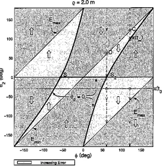
Figure 4. [oint-space trajectory evolutions for task
posi-tions that are located2m from the fh joint axis, e.g., task
positionsCandD.The large arrows denote the evolution
of the trajectory in a region. The end effectorposition error
increases in the light-gray regions, and decreases in the
dark-gray regions. The dark H-shaped curve indicates configurations to which the manipulator may converge,
i.e.,the commanded joint two velocity will be zero. Note
that the line corresponding to configurations that are
clos-est to the desired task positions (denoted Emin ) does not
coincide with the possible configurations of convergence. Thus, the end effector converges to a position that is not
closest toC.For task positionD,the manipulator does not
converge at all, but cycles continuously.
-30°), with the robot configuration given by 81
=0° and 82= - 30°, andis commanded to move
to-ward the task position until convergence. The joint-space trajectories for these cases are plotted in Figures
3and4as functions of 82and¢ (since 81is always0)
for p=l andp=2,respectively.For each particular task
position, ¢ is constant and the trajectory evolves
along the 82axis. For a given¢, the task positions are
characterized in these plots by 82=¢. Points of
con-vergence are at the intersection of the trajectory of 82
with the task position, or with the
8
2=0curve?Both the end-effector position error
E=llxd-Xall
and its rate of change
E
are shown in the plot. Theminimum and the maximum contours of the errorE
7InFigure4,the .92""0curveis discontinuous at positionsSl and
S2' For the given value ofp""2.0•.92is nonzeroatthese positions
II!
,i
1r
I
22 . Journal of Robotic Systems-lOOS! I I
,I
I I ti
o x,
x,
~··t----="-·'~
. ,.,:/.,." " '," . ' aFigure 6. Erroneous convergence when the desired task
positionXdis inthe postfailure workspace. With a joint1 failure the manipulator converges to a configuration where the "reduced-manipulator" becomes singular
eJ
=[hhJ
rank deficient), andXc
andh
align (Xi=
I-'
O.91.SJ T andXci=[1.51.5JT).and on the line xd=2. For such points, (15) gives 82
= - Yd'Thus, the manipulator rotates with a constant
angular velocity.
Remarks: Joint-space plots such as those in Fig-ures 3 and 4 are valuable workspace layout tools. As will be illustrated in Section 4.5, these plots can be used to identify regions of convergence where
suc-cessful task completion can be achieved even in the
presence of unidentified joint failures.
Figure 5. Successful convergence tothetask position. The manipulator is able to complete the point-to-point motion task between Xiand Xd' even with a failure of joint 2 (Xi =[2.0-1.4JT and x.t=[1.51.5JT).
are denoted by E~ and Em~,p respectively. In the
dark-gray regions, E is negative, and itis positive in
the light-gray regions.Ineach region, the evolution of
82isgovernedby(15) and is indicatedinthe plotsby
large arrows.
Case 1. Successful convergence. From Figure 3,
itcan be seen that for almostall
cp,
the 82trajectory isdrawn to the task position 82=
cp.
[One such exampleisshownwith point A (¢=45°).] This behavior is
ex-hibited only for p=1,i.e., when the task position lies
inthe postfailure workspace.Itwillbe seen that for
any other value ofP,not onlywillsuccessful
conver-gence not be achieved (since the task position lies out-side the postfailure workspace), but also the manipu-lator will almost always not converge to the point closest to that desired.
Even though successful convergence occurs for
p=l, the path taken by the end effector is dearly not
always the shortest. Also, the end-effector error
ini-tially increases for large regions of 82 and<p,leading
to large excursions of joint 2, which may violate joint limit constraints and therefore prevent convergence.
Itis also important to note that such behavioris not
preventable by simply restricting only the workspace
(by limiting
1»
or only the robot configuration (byconstraining 82 ) ,
Case 2. Erroneous convergence. Two types of er-roneous convergence are seen. The first is the unique situation where the task position (B) is in the post-failure workspace, but the robot does not move at all
(see Figure 3). Here, Xc and
h
are collinear and8
2=O. Indeed this condition is true for any 82 , and
therefore the robot does not move foranyinitial
con-figuration. Note that this behavior will be observed at every point on the boundary of the original
work-spaceifjoint 1 fails with the appropriate value for 81 .
The second, more common, type of erroneous
convergence is observed when the task position is
outside the postfailure workspace. Here, the end ef-fector does move, but converges to a point other than
one that minimizes the error,i.e., 82=1;.One such
ex-ampleis the point C shown in Figure 4. The figure
indicates that even for a constant value ofp,very
dif-ferent errors may be observed at convergence
de-pending upon the value of¢. The error is a minimum
for¢=180D
, and rises to a maximum for <pclose to 60°.
For the special case when4>=60°,no convergence
oc-curs; this is discussed next.
Case 3. No convergence. D is an example of a task position that lies outside the original workspace,
Godet al.: Analyzing Unidentified Locked-Joint Failures in Kinematically Redundant Manipulators 23
erroneously converges. An analysis of these configu-rations is thus necessary for a better understanding of the postfault behavior of the manipulator.
4.4. Conditions for Erroneous Convergence
The conditions of Theorem 1 can be used to deter-mine configurations of erroneous convergence for a
failed manipulator. Suppose the column of the
J
aco-bian corresponding to a failed revolute joint i is ex-pressed in standard Denevtt-Hartenberg notation as
(18)
end
Equations (19)-(21) represent the conditions that must hold for erroneous convergence. For a given failure angle of a joint, these equations can be solved for the other joint variables to determine the problem-atic configurations.
where coordinate frame (i-1) is attached to link (i
-1), the motion of jointi isalong the 7:;_1 axis, and
Pi represents the position vector of the end effector
expressed in the coordinate frame (i-1).Then,if
Xv
andXwrepresent the translational and rotational
com-ponents of
X
o the first condition is equivalent tosi-multaneously satisfying the following conditions:
(20) (19)
(21)
nt-(i)=O,
,
j=1,...,n-m.With pseudoinverse control (W=1), the rank
de-ficiency condition in Theorem 1 is equivalent to the
ith component of each of then - mlinearly
indepen-dent null vectors of Jbeing iindepen-dentically zero.12Thus if
{nj , ...,n] } represent any n-m linearly
tndepen-1 "-III
dent null vectors of
J,
then the second condition ofTheorem 1 is equivalent to
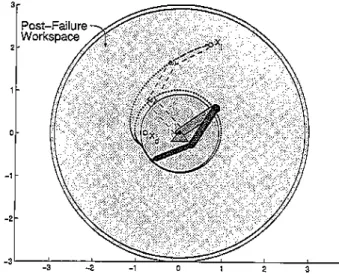
Figure 7. No convergence. With the choice of inverse-kinematics used, nonzero joint velocities are commanded in the healthy joints everywhere, therefore the
manipula-tor does not converge with the Joint 3 failure (~
=[0.7 2.lJT and:<0.=[-0.8 Of).
4.3 A 3-DOF Planar Example
Kinematic redundancy can be used to guarantee the postfailure reachability of task positions. However, potential problems with postfailure convergence
re-main eveninthis case, aswillbe demonstrated with
a planar 3-DOF example. All three distinct conver-gence behaviors are illustrated here with three ent cases shown in Figures 5-7. The failures of differ-ent joints are considered in these examples, and
pseudoinverse control is assumed. Ineach of these
cases the failed manipulator performs a
point-to-point motion task from an initial positionX;.to a
de-sired task positionXci' In the first case, shown in
Pig-ure 5, the manipulator is able to successfully complete the task even with a failure of joint 2. Illus-trated in Figure 6 is a case of erroneous convergence, where, even though the desired task position xci is the
same as in Figure 5 (and liesin the post-failure
work-space after a failure of joint 1), the manipulator
con-verges elsewhere. Presented in
Figure
7 is a casewhere no convergence is observed for the failure of
joint 3.Inthis case, the desired task position lies in the
original workspace, but outside the postfailure work-space. However, since at no position in the post-failure workspace are the conditions necessary for convergence satisfied, convergence is not possible. The manipulator therefore moves continuously.
The different convergence behaviors identified and illustrated above are characterized by the prop-erties of the configurations to which a manipulator
II!II
IJOint.2 Failure:45.0 d&\!, xd'• (1.501.50J
j
!I
,:1I
I
,
"'
'"
'00 ~50 ' 0, 0 0 ", ~OO ' ,.,"' ,... .."." . e-250 ,"' 200'·'J~L~_,,_,-.:J.
150 0 100 200 300 400 u (.) Join".,.·l '.5 1,5] 100 200 ~oo ecc o c.e " ".,.~::...
Joint1.', .(1.50 1.501 200' ""'~$;" , .... , . . ; '500 100 ~OO :300 400 <,..
250 ""." :."'"
""
",
"',
"
'"
• Journal of Robotic Systems-l005
24
Figure 8. Joint-space trajectories of a 3-DOF unit link
length, planar manipulator, with a failure of Joint 2 at 45°, S1 and 52 represent the two stationary configurations, while q,;olt and 'boll represent the two post-failure solu-tions corresponding to the desired position. The solid lines represent trajectories that are drawn to the stationary points; they also partition the joint space into the two ba-sins. All trajectories (shown by dashed lines) that originate inthe gray basin converge to qso1l' while those that origi-nate inthe unshaded basin converge to llsolf
4.5. Analyzing Stationary Configurations
After the stationary configurations of a manipulator are determined, an important question is whether a manipulator can be drawn into any of these configu-rations after a failure. The local behavior of the failed manipulator about a stationary point (qo) can be de-termined by analyzing the stability of the linearized
system dynamics about the point. For
q=
g(q), whereg(q)=iIGKc(Xd-xa), linearization about 'Io yields
200 25C (b) '00 15~ ""',
,
0.5 DOl'''''''"' .' '. 0.4 'mo>< " '; "]0.3\
.i " ,-' ,,0.2 " ; ' " r ~ \ r ' , !,
....\~~---~---~---~-~---~~--.
---~-~---~---,
.~,10 20 40 ao 80 'CO '20 '40 '8~Figure 9. Stationary curves for joint 1 failures of a 3-DOF unit link length planar manipulator are shown in (a). 51 and'52 denote the two seedconfigurations used to trace these curves. The sink segments are shown using dotted lines, while the nonsfnk segments are shown with solid lines. The segments are partitioned based on the behavior of the determinant and the real part of the eigenvalues of
it
shown in (b). The dashed lines in (b) define a "zero band" that is used to check for the zero crossings of the determinant curve. (22) d(agll·
-"q~-
"q~T~q· dt aq e, iI
Ii
Since the components of the vectors eq and (d /dt)~qcorresponding to the failed jointiare
ide_n-tically zero at a!:1 times after the failure, the matrix
ls,
obtained from
I
by removing the componentscorre-sponding to jointi,is examined for stability. While an
antistable equilibrium point (wherealleigenvalues of
Ii
have positive real parts) poses no problem as far aserroneous convergence of the manipulator is
con-cerned, a stable equilibrium point (all eigenvalues
have negative real parts) acts as an attractor andis a
Goel et al.: Analyzing Unidentified Locked-Joint Failures in Kinematically Redundant Manipulators 25
(a)nlOO
(c)
n ..
vg(b) .rlOO
eo 100"
Figure 10. Workspace shaded as a function of,7<.100' .rlOO,'R.;lvg, and'R.,;cns' for arbitrary joint failures (Xd= [1051.5JT).
is classified as a "sink." For an unstable equilibrium point (some eigenvalues have negative real parts), the stable modes can be used to trace the failure configu-rations for which the manipulator gets drawn to a sta-tionary point.
These traces, which are in general manifolds, may in some cases partition the workspace into dis-tinct regions or "basins," as seen for the 3-DOF ex-ample in Figure 8. Since trajectories originating off the basin boundaries can never reach these bound-aries, all trajectories are confined to the basins where they originate. Note that the Cartesian-space
trajec-tory shown in Figure 5 is an example corresponding
to a configuration that lies in the unshaded basin; it
thus converges to solution q,;,,12'
It is important to point out that unless the station-ary points are sinks, the dimension of the manifolds traced along the stable mode(s) is at least two less than the dimension of the joint space (or the number of DOFs) of the manipulator. This is because the fail-ure itself constrains one variable, reducing the di-mension by one, while the additional reductions in
dimension,if any, result due to the unstable modes.
probabil-26 . Journal of Robotic Systems-Z005
ity of a failure resulting in a manipulator
configura-tion ona problematic manifold is zero.
4.6. Tracing and Classifying Stationary Manifolds
For an analysis of correct convergence, all potentially problematic stationary configurations in the manipu-lator's joint space must be identified. The loci of these stationary configurations (referred to as "stationary manifolds") must be generated for every possible joint failure. The first step in tracing a stationary
manifold for a particular joint is to identify one
sta-tionary configuration for each distinct singularity of the failed arm. These stationary configurations rep-resent the set of seed configurations that are grown to trace out the entire stationary manifold. Since (19)-(21) must hold at all stationary configurations, the loci of stationary configurations can be traced by sim-ply starting at a seed that satisfies these conditions, and moving in a direction orthogonal to the gradients of the right-hand side components of these equations. Doing this for each seed allows all the loci to be traced. More specifically, a matrix M is formed by col-lecting the gradients, and joint motion in the null space of M traces the manifolds [see Figure 9(a)].8 The
rank of M may drop along a trace, signifying the
in-crease in the dimension of the null space, and hence
a branchinginthe manifold. This is an issue that must
be addressed in the implementation of this technique. Sinks, being the real hindrance to correct conver-gence, must be identified on the stationary manifolds. This is done by checking the eigenvalues of;i at each point on the discrenzed manifolds. For manipulators with exactly one degree of redundancy (as in the
3-DOF exampleconsideredr.j.issquare, andinsuch
cases the partitioning process can be performed more
efficiently by evaluating the determinant of
i..
andchecking the eigenvalues only at the zero crossings of the determinant. This is because only at these zero crossings can the eigenvalues change sign. The sta-tionary manifolds can thus be partitioned into "sink" and "nonsink" segments [see Figure 9(b)].
S. WORKSPACE ANALYSIS
The postfailure convergence behavior of manipula-tors, in addition to being functions of other variables,
"Tracing stationary manifoldsin high dimensions isingeneral a difficult problem. While there exist techniques for tracing2-D
manifolds, such as the one presented in ref.24,the formulation of general methods to trace such surfacesinhigher dimensions is an open problem.
is seen to be dependent on task placement.Iffailure
identification is not available, or otherwise, not reli-able, this knowledge can be exploited to better cope with failures. Through the characterization and clas-sification of workspace regions, critical tasks can be
placedinlocations to which the manipulator can
cor-rectly converge even after an. arbitrary joint failure. Analyzing the workspace of a manipulator for failure tolerance involves checking for reachability and correct convergence. Based on the ideas pre-sented in the previous sections, a systematic proce-dure can be developed to analyze a manipulator's workspace. For the given task model of point-to-point motion- a specified control scheme, and a
de-sired task position, it is of interest to evaluate theen~
tire workspace to determine the effect of the initial task position on the convergence behavior of a ma-nipulator when anticipating unidentified locked-joint failures. Some concerns when evaluating a candidate initial task position are the following.
• For what percentage of the trajectories
origi-nating on the self-motion manifolds of the
ini-tial position can reachability of the desired
po-sition be guaranteed?Ifreachability cannot be
guaranteed for a failure along the entire trajec-tory, then for what percentage of the trajectory can reachability be guaranteed?
• How much does the percentage reachability change 'With the initial configuration? That is,
how sensitiveisreachability to a choice of the
initial configuration?
Similarly, questions about correct convergence to the desired position can be posed for trajectory portions guaranteeing reachability.
For a given desired task position, the following procedure allows the workspace to be evaluated for identifying the suitability of different initial positions
for the task," The first step ofthe procedureisto
dis-cretize the entire workspace. The disdis-cretized posi-tions in the workspace represent the set of initial po-sitions to be evaluated. Since, in general, a redundant manipulator can reach each of these positions with an infinite number of configurations, a Set of initial con-figurations must be considered. This set of configu-rations is obtained from the discretized self-motion manifoldls) corresponding to the initial configura-tion. The procedure for the analysis is summarized in the following pseudocode.
"Iheeffectofthe choice of thefinal position on the convergence behavior, for a giveninitialposition, can be addressedina similar manner.
,
:1'.~
I ,'I
IGoel et al.: Analyzing Unidentified Locked-Joint Failures in Kinematically Redundant Manipulators • 27
eGenerateBd
(the union of the bounding boxes of all the
self-motion manifolds ofXd,the desired task position)
«Discretize the workspace to get a set of initial positions
xli),
i=
1 :nXifori
=
1 ;nj/s(for each joint)«Generate S,.(the union of all the stationary
manifolds) and classifyS,.into sinks/non-sinks
end
fori
=
1 :nXi(for each initial end-effector position)eGenerate the self-motion manifold(s) for Xi(i)
forj
=
1 :nq,.(for each discretized configuration on the manifold(s))eCompute the forward trajectoryT)toXufor the healthy manipulator
eCompute
T),.",
the portion ofTjinsideBXdfori
=
1 :nj/s(for each joint)-Computethe intersection of the range
of motion of jointiover T),.", with the
corresponding range over sink(SD
for
Tj,."
n S,.eFor each discretized point on the
overlap, assume a failure of jointi
and check whether or not the
manipulator converges to Xd
end
(Tj;"n S,. empty=>The task is
tolerant to joint i failures overTI. )
"m
end
(T)lfln SI empty for i
=
I :/1,)/.,=>The task istolerant to an arbitrary joint failure overTI. )
"m
end end end
The data obtained from the implementation of this procedure can be interpreted in a variety of ways; however, the questions posed earlier in this section are best addressed by the following measures:
RI GO: The percentage of configurations
consid-ered for Xi' for which reachability ofXcican be
guar-anteed for the failure of ajoint alongtheentire length
of the nominal trajectory.
Ravg : The percentage length of the nominal tra-jectory for which reachability to xa can be guaranteed for the failure of a joint, averaged over all considered configurations.
'R..sen~:The difference between the maximum and minimum, over all considered configurations, of the percentage of the trajectory for which reachability to xa can be guaranteed for a joint failure. This measure
r
II
I.
I
28 • [oumal oj Robotic Systems-2005
reflects the sensitivity of reachability to a choice of the
initial configuration corresponding to Xi'
Analogous measures for complete fault tolerance (correct convergence), over trajectory segments
guar-anteeing reachability, are given by FlOG, Fav g , and
Fsens ' respectively.
All measures are computed for the possibility of a failure of a specific (known) joint, as well as that of
an arbitrary (unknown) joint,10
5.1. AnIllustration
The application of the workspace analysis procedure
proposed above is illustrated for the example of a
3-DOF planar manipulator with unitlinklengths. The
desired position considered in this example of a
point-to-point motion task is Xd=[1.51.5]T, The
workspace of the manipulator is sampled on an equally spaced square grid, using 2032 samples. Each of these samples is evaluated as a candidate initial P'> sition for the task. The stationary manifolds for this example are generated and partitioned into sink and nonsink segments as discussed in Section 4.6. The
bounding box BXdfor the single self-motion manifold
corresponding to xa is computed using the technique
outlined in Section ill. The bounds are [-24.30°
11"30'1, [-111.80' 111.80'1, and [-111.80' 111.80'], for
joints 1, 2, and 3, respectively.InFigure 10 the
work-space is shaded as a function of four of the six
pro-posed measures:'R.100 , 'R,avf;' 'R.sens ' andF lOO,
consid-ering arbitrary failures. These plots demonstrate how the failure tolerance properties of the manipulator change over the workspace. Since the measures change in a continuous manner over the workspace, these plots can be used to identify regions that
guar-antee a certain level of failure tolerance. Itis noted
thatingeneral all regions with nonzero reachability
measures'R,lOoand'R,avgexhibit high values of the
cor-responding comprehensive fault tolerance measures FlOOand .r,wg(not shown).Inother words, most
tra-jectory segments that guarantee the reachability of the task position also guarantee correct convergence.
Though this is true for xa in this example,itmay not
be guaranteed for an arbitrary choice of task position.
Itwas also seen that the comprehensive sensitivity
measureF sffiS (not shown) is very low over the
work-space, implying that, for this example, if reachability
lOWhen a specific joint is considered, only projections of trajecto-ries and bounding boxes for that joint axis are relevant.
is guaranteed, correct convergence has little
depen-dence on the initial configuration of the manipulator. Figures 5 and 6 are examples of postfailure conver-gence behaviors that could be predicted by studying similar plots of workspace measures. While not shown here, it turns out that the initial positions of
the manipulator inboth Figures 5 and 6 are
charac-terized by perfect measures of'R,100,i.e.,100%, for the
failures of joints 2 and 1, respectively.Itis the
differ-ing values of the corresponddiffer-ing F100 measures of
these positions that result in the different
conver-gence behaviors. The initial position considered in
Figure 5 is characterized by a highFlOGmeasure, and
so correct convergence is almost always observed for a failure. The case presented in Figure 5 is an example
of such behavior. On the other hand, the initial
po-sition considered in Figure 6 is characterized by a low
FlOO measure, and consequently incorrect
conver-genceisseen for a significant number of failure
con-figurations.An example of this problem is illustrated
by the case presented in Figure 6. Workspace plots
such as those shown in Figure 10 can thus be effec-tively used for an off-line prediction of the postfault behavior of a manipulator.
6. CONCLUSION
In this work the behavior of robotic manipulators
performing point-to-point motion tasks with uniden-tified locked-joint failures was analyzed. Conditions governing convergence issues such as whether the
manipulator comes to rest, andifso, at what terminal
position of the end-effector, were explicitly defined and the different possible convergence behaviors, il-lustrated with examples. A general procedure for evaluating the failure-tolerance properties of a ma-nipulator over its workspace was also presented.P Since no closed form expressions to guarantee correct convergence exist, brute-force evaluations to check for the effect of certain failures become necessary over some portions of the workspace. However, the procedure based on the developed analysis tools al-lows for an intelligent evaluation of the workspace, thereby minimizing the number of brute-force checks. Using workspace information for task place-ment is an effective approach to coping with failures, with or without failure identification.
llThe analysis procedure can be extended,ina manner analogous to the one in ref. 27, to design manipulators that are guaranteed to convergein the post-failure workspace.
i
I II 'I :\____.rIi
Goel et: al.: Analyzing Unidentified Locked-Joint Failures in Kinematically Redundant Manipulators 29
REFERENCES
1. B.S. Dhillon, Robot reliability and safety, Springer-Verlag, New York, 1991.
2. R Colbaugh and M. Jamshidi, Robot manipulator
con-trol for hazardous waste-handling applications,
J.
Ro-bot Syst, 9:(2) (1992),215-250.3. M.L. Visinsky, J.R. Cavallaro, and LD. Walker, Robotic fault detection and fault tolerance: A survey, Rehab Eng Syst Safety 46 (1994), 139-158.
4. Unimation Incorporated, Unimate Puma Mark II Ro-bot 500 Series Equipment Manual, Danbury, CT, 1985.
5. K.N. Groom, AA. Maciejewski, and V.Balakrishnan,
Real-time failure tolerant control of kinematically re-dundant manipulators, IEEE Trans Robot Autom 15:(6) (1999), 1109-1116.
6. J.D. English and A.A Maciejewski, Fault tolerance for kinematically redundant manipulators: Anticipating free-swinging joint failures, IEEE Trans Robot Autom 14:(4) (1998),566-575.
7. G. Liu, Control of robot manipulators with consider-ation of actuator performance degradconsider-ation and fail-ures, in 2001 Int Com Robot Autom Seoul, Korea, IEEE, 21-26 May, 200l.
8. E.C.WU,J.e. Hwang, and J.T. Chladek, Fault-tolerant joint development for the space shuttle remote ma-nipulator system: Analysis and experiment, IEEE Trans Robot Autom 9:(5) (1993),675-684.
9. A.K.Pradeep,P.J. Yoder,R Mukundan, and
R.J.
Schill-ing, Crippled motion in robots, IEEE Trans Aerosp Electron Syst 24:(1) (1988),2-13.10. e.L. Lewis and AA Maciejewski, Dexterity optimiza-tion of kinematically redundant manipulators in the presence of failures, Comput Elect Eng 20:(3) (1994), 273-288.
11.Cn Paredis, W.K.F. Au, and P.K Khosla, Kinematic
design of fault tolerant manipulators, Comput Electr Eng 20:(3) (1994),211-220.
12. R.C.Roberts and AA. Maciejewski, A local measure of fault tolerance for kinematically redundant manipula-tors, IEEE Trans Robot Autom 12:(4) (1996), 543-553. 13.RG. Roberts, On the local fault tolerance of a
kine-matically redundant manipulator,
J
Robot Syst 13:(10) (1996), 649-661.14.W.E.Dixon, LD. Walker, and D.M. Dawson, Fault de-tection for wheeled mobile robots with parametric un-certainty, in 2001 Int Conf Advanced Intelligent
Mechatronics. VoL 2. IEEE! ASME, 2001, pp.
1245-1250.
15.M.B. Terra and R.Tines,Fault detection and isolation in robotic manipulators via neural networks; A com-parison among three architectures for residual analy-sis, J Robot Syst 18:(7) (2001),357-374.
16. L. Notash, Joint sensor fault detection for fault tolerant parallel manipulators,
J
Robot Syst 17:(3) (2000), 149-157.17. M.L. Visinsky, J.R. Cavallaro, and LD. Walker, A
dy-namic fault tolerance framework for remote robots, IEEE Trans Robot Autom 11:(4) (1995),477-490. 18. Y. Ting, S. Tosunoglu, and D. Tesar, A control structure
for fault-tolerant operation of robotic manipulators, in 1993 Int. Conf. Robot Autom, Atlanta, GA, IEEE, 2-6 May, 1993, pp. 684-690.
19. I.E.Mcinroy, I.E O'Brien, and G.w' Neat, Precise, fault-tolerant pointing using a stewart platform, IEEE! ASME Trans Mechatron 4:(1) (1999),91-95.
20. J.E. McInroy, G.w' Neat, and J.F. O'Brien, Robotic ap-proach to fault-tolerant, precision pointing, IEEE Ro-bot Autom Mag 6:(4) (1999), 24-31.
21.D. Urnand V. Lumelsky, Fault tolerance via analytic redundancy for a modularized sensitive skin,IntJ Ro-bot Autom 15:(4) (2000),155-165.
22. B.M. Harpel,
J.B.
Dugan, LD. Walker, and J.R. Caval-laro, Analysis of robots for hazardous environments, in Proc of the Annual Reliability and Maintainability Symposium, Philadelphia, PA, January 1997, pp. 111-116.23. S. Kimura, M. Takahashi, T.Okuyama, S. Tsuchiya,
and Y. Suzuki, A fault-tolerant control algorithm hav-ing a decentralized autonomous architecture for space hyper-redundant manipulators, IEEE Trans Syst Man, Cybem SMC-28:(4) (1998), 521-527.
24.C'l..Lewis andA.A.Maciejewski, Fault tolerant opera-tion of kinematically redundant manipulators for locked joint failures, IEEE Trans Robot Autom 13:(4) (1997), 622-629.
25.CnParedis andP.KKhosla, Mapping tasks into fault tolerant manipulators, in 1994 Int Conf Robot Autom, San Diego, CA, IEEE, 8-13 May, 1994, pp. 696-703.
26. F. Miyazaki and Y Masutani, Robustness of sensory
feedback control based on imperfect Jacobian, in Ro-botics Research: The Fifth International Symposium,
H. Miura and S. Arimoto, eds. 11IT, Cambridge, 1989, pp. 201-208.
27. M. Shoham and Y Koren, Motion control algorithms for sensor-equipped robots, ASME J Dyn Syst Measure Control 109 (1987), 335-344.
28. Y. Ting, S. Iosunoglu, and B. Fernandez, Control algo-rithms for fault-tolerant robots, in 1994 Int Conf Robot Autom, San Diego, CA, IEEE, 8-13 May, 1994, pp. 910-915.
29. Y. Ting, S.'Iosunoglu,R. Freeman, and D. Tesar, Satu-ration avoidance methods for serial robots operating under a failure, J Robot Syst 16:(12) (1999), 667-678. 30. E. Wu, J. Hwang, and
J.
Chladek, A failure tolerantjoint design for the space shuttle remote manipulator system: Analysis and experiment, in First IEEE Com Control Applications, Dayton, OH, 13-16 September, 1992, pp. 330-335.
31. CLLuck and S. Lee, Self-motion topology for redun-dant manipulators with joint limits, in 1993Int Com Robot Autom, Atlanta, GA, IEEE, 2-6 May, 1993, pp. 626-631.