Reliable RSS-based Routing Protocol for Industrial
Wireless Sensor Networks
Kan Yu
∗, Mikael Gidlund
†, Johan ˚
Akerberg
†and Mats Bj¨orkman
∗ ∗M¨alardalen University, Sweden†ABB AB, Corporate Research, Sweden
Abstract—High reliability and real-time performance are main research challenges in Industrial Wireless Sensor Networks (IWSNs). Existing routing protocols applied in IWSNs are either overcomplicated or fail to fulfill the stringent requirements. In this paper, we propose a reliable and flexible Received Signal Strength-based routing scheme. Our proposed solution can achieve a seamless transition in the event of topology change and can be applied in different industrial environments. The sim-ulation results show that our solution outperforms conventional routing protocols in both reliability and latency. Furthermore, the result also proves that the changes of the network topology have no impact on data transmissions of other nodes by our scheme, whereas conventional routing protocols are shown to fail to recover the network in a short time. Finally, due to dynamic weighting mechanism, the proposed scheme is verified to achieve significantly higher reliability in scenarios with obstacles and avoid installation troubles, compared to location-based flooding scheme. Thus, our proposed scheme is considered to be more suitable for IWSNs than other routing protocols.
I. INTRODUCTION
While a great number of benefits are derived by replac-ing Industrial Sensor Network (IWSN) of traditional wired counterpart for industrial automation, such as convenient de-ployment and cost efficiency, more challenges are faced to satisfy the stringent requirements from industrial applications, such as process automation (PA). When IWSNs are deployed in a hash industrial environment, the vulnerability of wireless signal leads to high risk of transmission failure and then results in missing or delaying of process or control data. However, for industrial automation, missing the process or control deadline is intolerable, which may terminate industrial application and finally result in economic loss.
WirelessHART [1], ISA [2] and WIA-PA [3] are three major industrial communication standards for process and control ap-plications. They are specifically designed to meet the enforced requirements on reliable and low latency transmission. For instance, in order to provide deterministic performance, the medium access mechanism combines Time Division Multiple Access (TDMA) with a contention-based approach. In IWSNs, a routing protocol plays a vital role in real-time communi-cations to guarantee process data arriving at the destinations before their deadlines. Currently, there exist a great number of routing protocols in WSNs [4] [5] [6] [7] [8] [9]. How-ever, very few of them fulfill the industrial requirements of both high reliability and low latency [10]. They either are designed for energy constrained systems without focusing on improving reliability [5] [6], or involve heavy control message
overheads for maintaining routing information [7] [8], or are overcomplicated for sensor nodes [4] [9]. Although extensive research efforts have been taken to investigate available routing schemes in IWSNs, existing solutions are not completely suitable for IWSNs.
To overcome the drawbacks of current routing schemes, a location-based flooding approach [11] was proposed. However, the inherent disadvantages of location-based scheme, such as difficulties in node installation, limit the use of this routing approach. Therefore, in this paper, we propose an advanced Received Signal Strength (RSS)-based flooding scheme. Our approach contains two main components. First, each node within the network needs to be assigned with a weight value. The sink periodically broadcasts a weight-updated message to all other nodes. Each node weights itself via Received Signal Strength Indicator (RSSI) values of incoming messages and the message weight according to our proposed weighting algorithm and forwards the message to other nodes. After the weight-updated messages are spread out within the whole net-work, all nodes obtain a weight value indicating its ”logical” communication distance to the sink. Secondly, when a node intends to transmit packets to the sink, the node inserts its own weight into its packets and broadcasts it to its neighbors. All packets from this node are only forwarded by the intermediate nodes with less weight. Since the sink is assigned with the weight zero, all packets will finally arrive at the sink. Based on our proposed routing approach, any path failure or change of the network topology will not trigger a route recalculation and interrupt data transmissions, since our proposed approach is entirely free of routing tables. Besides this advantage, by utilizing our solution, node installation becomes much more convenient without measuring the position, when compared with location-based flooding scheme. Since signal strength is used for weighting nodes, the weight value of our solution is more accurate and realistic than location-based weighting method by avoiding geographical obstacle problem. Since IWSNs are typically centralized network that each node only communicates with the sink, peer-to-peer communication be-tween any two end nodes is not considered in this paper.
The reminder of the article is organized as follows. Section II reviews the previous works on existing routing schemes in WSNs. The details of our proposed reliable RSS-based flooding scheme are introduced in Section III, followed by Section IV where details of simulation and scenarios of interest are presented. Simulation results and analysis are given in
Section V. Conclusions are drawn and summarized in Section VI.
II. PREVIOUSWORK
Based on different mechanisms, current existing routing schemes in WSN can be classified as five categories, which include flooding-based, dynamic routing table-based, cluster-based, geographical and self-organizing schemes. Among them, cluster-based [12] and self-organizing routing schemes [4] are mostly used for adhoc network, so they are not appro-priate solutions for centralized IWSNs. Geographical routing protocols [5] are usually designed for energy constrained purpose without considering reliability and latency. Therefore, flooding-based and dynamic routing table-based schemes are considered as potentially available solutions for IWSNs.
Flooding-based routing protocols have the advantages of not requiring path discovery or maintenance of routing in-formation and achieve high reliability by multipath diversity. However previous flooding schemes fail to satisfy industrial requirements. The approach by Akkaya and Younis [13] aims at avoiding the drawbacks of flooding by randomizing the selection of retransmitters, but it is unacceptable in IWSN settings. A random routing strategy for WSNs based on flooding in [6] aims for low energy consumption. However, this results in even higher latency.
Dynamic routing table-based routing schemes have been commonly used in IWSNs. Many conventional routing pro-tocols, such as Ad hoc On Demand Distance Vector (AODV) routing algorithm, Dynamic Source Routing (DSR), are sorted as this type. However, in industrial environments, link failures are common and frequent. To maintain the connectivity, for table-based routing schemes, excessive control messages are inevitable. A path failure or change of the network topology usually triggers route recalculation, which may prolong the transmission latency. Although a number of extensions of con-ventional routing protocols were proposed, such as AOMDV [7], an extension of AODV, and SMR [8] as a multipath version of DSR, primary drawbacks of routing table-based routing schemes still exist.
Among the latest research works, several routing protocols were proposed specifically for IWSNs. A location-based flood-ing approach [11], as a combination of traditional floodflood-ing and geographical schemes, were proposed. Although this scheme succeeds in improving both reliability and transmission la-tency, there exist two fatal drawbacks of this approach. First is that this solution is based on the assumption that better link quality can be obtained by shorter geographical distance, which does not hold all the time. Second disadvantage is that this scheme makes the installation of nodes extremely difficult and inefficient. Authors from [9] proposed entire graph routing schemes for broadcasting, uplink and downlink for IWSNs. They tried to maximize the reliability, meanwhile minimize the power consumption. However, their method for constructing routing graphs is complicated for sensor nodes and the network recovery time is not evaluated. Therefore, to find a more
lightweight, robust and efficient routing scheme for IWSNs is extremely important.
III. PROPOSEDRELIABLERSS-BASEDFLOODING
SCHEME
Our proposed scheme consists of two primary components, namely node weighting method and forwarding criteria. In this section, we first introduced industrial wireless channel con-ditions as background knowledge. Then we describe how we label each sensor node with a weight, followed by introduction of packet forwarding criteria for intermediate nodes. Finally, an example based on our proposed solution is given.
A. RSS-based Principle
Industrial wireless channel condition is considered to be hash and dynamic due to metallic surfaces, extreme temper-ature, high vibrations and non-line-of-sight (NLOS) commu-nications. In order to characterize wireless channel conditions in real industrial environments, a measurement from [14] was done in a power plant. In one of their measurement scenarios, one sensor node continuously sent data to another node with the distance of 10 meters NLOS. The result shows that around 90% of the RSSI concentrates between -65 dBm and -55 dBm. In another scenario of their measurement, when two nodes were apart from 30 meters away NLOS, the RSSI values drop to -71± 3.2 dBm. Another measurement from an industrial factory [15] also shows that the fluctuations of RSS are about 25 dBm. It is notable that, in industrial environments, although the RSSI varies from different packets, most of the values are scattered in a limited range and objectively indicates the link quality between two nodes. Hence, the RSSI can be used as a parameter for weighting nodes in our solution.
B. RSS-based Weighting Method
As one of the primary components of our proposed scheme, each sensor node in the network should be assigned with a weight value a through weighting procedure. A weight represents the logical network distance between the node and the sink, rather than geographical distance. A node with higher weight indicates more hops or weaker signal strength to the sink. The sink has the minimum weight in the whole network and a joining node is initialized with a predefined maximum weight. Since the weight plays a critical role when forwarding packets, the method of assigning weights to each node shall be accurate. As mentioned above, the RSSI is an appropriate parameter for weighting nodes. We define the weight as the absolute value of RSSI in dBm.
In order to weight all nodes in the network, the sink periodically broadcasts a weight-updated message. This mes-sage contains three types of important information: i) packet weight; ii) the node ID of previous hop; iii) hop number. They are initialized with zero, sink ID and one respectively. After being sent by the sink, this message is rebroadcasted by other nodes until it is spread out in the entire network. The rebroadcasting procedure by an intermediate node is summarized in Algorithm 1, where wpkt is the weight of
received packet, wbuf is the node buffered weight, wnode is
the current node weight, hpkt is the packet hop number and
hbuf is the node buffered hop number. wpkt and hpkt not only
help sensor nodes calculate new weights, but also prevent the message from endless forwarding. A broadcast threshold is required, which helps the node filter out unstable links. Algorithm 1 Weight-updated Message Rebroadcasting
1: if RSSI of received message ≥ broadcast threshold then 2: if hpkt≤ hbuf then
3: Store the node ID of the previous hop
4: if (wpkt+ |RSSI|) < wbuf then
5: wpkt= wpkt+ |RSSI|
6: wbuf = wpkt
7: hbuf = hpkt
8: hpkt= hpkt+ 1
9: Replace node ID of previous hop with its own ID
10: Rebroadcast 11: else 12: Drop 13: end if 14: else 15: Drop 16: end if 17: else 18: Drop 19: end if
After all sensor nodes receive the weight-updated messages, a response message to the sink from every node is required. This response message contains buffered weight, buffered hop number and all parent node IDs. Before the new weight being activated, all nodes still use the old weight to upload the response to the sink. After the sink collects responses from all nodes, it has the knowledge of the latest network topology. Since TDMA mechanism is used on the MAC layer, nodes closer to the sink require more transmission opportunities for serving both as sources and intermediators. The sink needs to make an appropriate scheduling decision according to the network topology in order to avoid network congestions. In our solution, a simple TDMA scheduling is utilized that more time slots are assigned to the nodes with lower weight, smaller hop numbers and higher refresh rate. If the network is schedulable, since the network topology is known by the sink, the allocation of the time slots is straightforward; otherwise, the network should be rebuilt. Finally, a confirmation message containing the latest scheduling decision and the activation time slot offset is broadcasted by the sink. After all nodes receive the confirmation message, the new node weight and scheduling scheme will be applied at the specific time slot informed by the sink. Buffered weight, buffered hop number and parent IDs in the node also need to be reset.
C. Forwarding Criteria
After all nodes are assigned their weights, the next essential step is to formulate packet forwarding criteria. First, we
introduce four basic forwarding criteria, whose validity is a necessary condition for packet forwarding to occur.
Criterion C1: same packets shall only be forwarded for once.
Every packet contains a unique (i, s) pair, where i is the source node ID and s is a unique sequence number for every packet generated by the node. By this pair, a node is able to unambiguously identify unseen packets. Duplicates are discarded. Meanwhile, each node shall manage a history table to store (i, s) pairs. Items in the history table shall be flushed according to the refresh rate of incoming packets in order to prevent the wrap-around of sequence number.
Criterion C2: a packet is allowed to be forwarded only if the packet weight is larger than the current node weight plus a margin, that is if:
wpkt> wnode+ wmargin (1)
where wpkt is the weight of received packet, wnode is the
weight of current node and wmargin is a predefined margin.
Besides the unique pair (i, s), each packet also contains the packet weight wpkt inserted by the source or the forwarders.
Since the weight represent the communication distance be-tween the node and the sink, this criterion shows that a packet must progress towards the sink at every hop. The packet weight wpkt shall be replaced with the current node weight
wnode before being sent out. However, if the difference in
weights is small, it indicates that the communication distances from these two nodes are approximately the same. Thus, it is unnecessary to forward the packet to save network resources for transmitting other packets. Therefore, the margin wmargin
is added to filter out incoming packets from the nodes with similar distance to the sink. The margin value depends on the variation of the channel status. Typically, huge variation of channel condition leads to a larger margin.
Criterion C3: a packet shall be forwarded only if the RSSI of this packet is larger than a predefined forwarding threshold: RSSIpkt> f orwarding threshold (2)
This forwarding threshold directly decides the number of neighbors whose packets a node considers for forwarding. By varying this value, a node can increase or decrease the number of its neighbors. Since the sink is aware of the network topology, the number of time slot assigned to a node is referred to the number of its neighbors. Without the forwarding threshold value, a packet may reach a node from very far away which does not have enough slots to serve more nodes. Therefore, the forwarding threshold is important to guarantee the deterministic transmission and prevent the network congestion.
Criterion C4: A packet is considered for forwarding if the packet age Tage is less than the refresh rate of its originating
sensor Tref resh:
(a) Original Network Topology (b) Weight-Updated Route (c) Packet Forwarding Route Fig. 1. An example of proposed scheme: R indicates the signal strength, W indicates the weight value
Outdated packets are meaningless to industrial applications, since new data is generated. Discarding these useless packets can save the network resources as well. Different from previ-ous three criteria, criterion C4 is checked before the packet is forwarded, since packets are buffered in the node until having dedicated time slot to be transmitted. This waiting period may lead to the expiration of the packet.
Besides these four basic forwarding criteria, in order to improve the reliability and guarantee deterministic commu-nication, one more conditions is also required to be fulfilled. From the measurement in [14], the RSSI value varies in a certain range. It indicates that the RSSI value of a packet sent by a neighbor node can be lower than the threshold value. Meanwhile, it is also possible that a packet from another node which is far away from the current node has the RSSI value larger than the threshold value. Both of these cases may affect the overall performance of our proposed solution. In order to prevent these cases from happening, each node shall maintain two extra tables to memorize friends and travelers. Friendsrepresents the nodes whose packets are expected for forwarding and travelers means the opposite. In the initialized stage, the lists of both friends and travelers in the node is empty. All other nodes are initially considered as strangers. Acquaintance time is defined according to the refresh rate of incoming packets, which can be calculated by 10 times or 20 times of the refresh rate. If a node successfully receives more than 50% of packets from another node during the acquaintance time, this node is memorized as a friend. If less than 20% of packets are received, the source node is added into the traveler list, otherwise it is still considered as a stranger. Privilege is granted to friend nodes that even if the RSSI value of packets from friend nodes is less than the threshold, its packets are still allowed to be forwarded. Meanwhile, even if the RSSI value of packets from travelers is higher than the threshold, those packets are discarded. Finally, the proposed forwarding process based on previous criteria and conditions is summarized in Algorithm 2. If the channel status does not vary a lot, Algorithm 2 can be greatly simplified. Then only four forwarding criteria are checked for every packet without sorting the types of the source node.
As we described above, a packet can reach the sink by our solution without routing tables. During our routing procedure,
broadcastthreshold and wmargin should be well defined
according to the industrial environment. This can guarantee that every packet from a node will always find an available path to the sink. Thus the situation that a node is surrounded by higher weighted nodes that always drop its packets will rarely happen.
Algorithm 2 Packet Forwarding Procedure
1: Extract (i,s) and wpkt from the received packet
2: if stranger then
3: if C1∧ C2∧ C3∧ C4= true then
4: Insert (i,s) in the pair table
5: if unseen source ID then
6: Calculate the acquaintance time and store the ar-riving time and node ID
7: else if the acquaintance time is over then
8: if friend then
9: Add the node ID to the friend list
10: else if traveler then
11: Add the node ID to the traveler list
12: else
13: Clear all stored information
14: end if
15: else
16: Increase the number of received packet by one
17: end if 18: wpkt = Wnode 19: Forward 20: else 21: Drop 22: end if
23: else if friend then
24: if C1∧ C2∧ C4= true then 25: wpkt = Wnode 26: Forward 27: else 28: Drop 29: end if
30: else if traveler then
31: Drop
D. Example: RSS-based flooding scheme
Figure 1 illustrates an example of our proposed flooding scheme in an IWSN. The original topology of the network is shown in Figure 1(a) and the dash lines in the networks represent all possible available links.
To update weights of all nodes, the sink periodically broadcasts a weight-updated message in the whole network. Propagation routes of the weight-updated message are shown as arrows in Figure 1(b). The number in each arrow is the received RSSI value when the message arrives at a node. The solid arrows represent that a weight-updated message is received and rebroadcasted by the receiver, whereas the dash arrows indicate that the message is received, but discarded or not considered by the receiver according to our proposed rebroadcasting algorithm. For instance, the node S1 can re-ceive two weight-updated messages: one is from the sink, the other is rebroadcasted by the node S2. The later message is discarded due to the larger hop number, compared with the message directly from the sink. To take another exam-ple, the node S5 can receive three weight-updated messages respectively from node S1, S2 and S3. Since the message from the node S2 has the lightest accumulated weight, namely 63 + 54 = 117, the messages from the other two nodes will not be considered. Besides calculating new weight, each node shall also records node IDs which sent it the messages with the minimum hops number. For example, the node S5 shall record nodes S1, S2 and S3, since they all sent it weight-updated messages with hop number 2. Afterward, each node will generate a response message to the sink, containing the new weight and all parent node IDs. When the sink gets all responses, a new appropriate scheduling scheme is generated. Taking the node S2 as an example, considering all nodes have the same refresh rate, since all nodes S4, S5 and S6 report the node S2 as their parent node, the sink will assign at least 3 + 1 = 4 time slots for the node S2. Finally, the sink will broadcast a confirmation message to all nodes to activate the new weight and new scheduling scheme.
The packet forwarding behavior is described in Figure 1(c). The node S4 is the source node, intending to transmit packets to the sink. The solid arrows indicate the valid packet forwarding routes from the source to the destination. Packets delivered via dash arrows will be discarded according to the proposed forwarding algorithm. For instance, packets are not allowed to be sent to a node with higher weight. Finally, packets from the node S4 arrive at the sink. It is obvious that the multipath diversity is achieved by our proposed solution to improve the reliability.
IV. EXPERIMENTALSETUP
The proposed scheme is evaluated in QualNet simulator. In this section, we describe the simulation environment and measurables of interest, as well as the simulation scenarios. A. Simulation environment and measurables of interest
In Qualnet, an IWSN, constructed by one sink and a number of sensor nodes, is placed within a 100 × 100 m area.
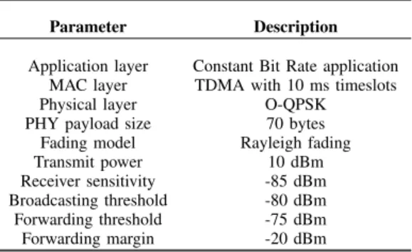
TABLE I
THE SIMULATION PARAMETERS
Parameter Description
Application layer Constant Bit Rate application MAC layer TDMA with 10 ms timeslots
Physical layer O-QPSK
PHY payload size 70 bytes Fading model Rayleigh fading
Transmit power 10 dBm
Receiver sensitivity -85 dBm Broadcasting threshold -80 dBm Forwarding threshold -75 dBm Forwarding margin -20 dBm
Each sensor node periodically sends measurement data to the sink. Protocol stack used in the experiments has the essential common properties of the existing IWSN standards, as shown in Table I. The length of PHY payload is chosen as 70 bytes, since it is the typical length for process data. Since NLOS communication happens most of the time in industrial environments, the channel model is chosen as Rayleigh fading, with fluctuations of received RSSI variations of around 22 dBm, which is a realistic variation according to measurement in real industrial environments [14] [15]. The parameters used in the proposed scheme are also shown in Table I.
B. Simulation Scenarios
In order to evaluate the improvement, we tested our pro-posed solution against three different scenarios.
1) Scenario I: The topology of IWSN is randomly gener-ated and shown in Figure 2. The nodes have a refresh rate 500 ms, which is also the deadline. The measurables of interest in this scenario are PDR, the average end-to-end delay and the maximum end-to-end delay. PDR exhibits the reliability of each routing scheme. Two types of PDRs are examined in our simulation. First type is P DRoverall as the overall
PDR in the network regardless of the deadline, whereas the second type is P DRdeadline, only considering packets, which
arrive at the sink within their deadlines. The overall latency performance is represented by the average end-to-end delay, whereas the maximum end-to-end delay reveals whether or not the routing scheme is suitable for real time industrial communications. We compare our proposed scheme with the location-based flooding scheme, as well as three conventional routing protocols, namely AODV, DSR and Dynamic MANET On-Demand (DYMO) protocol.
2) Scenario II: Generally, if a node is placed more than one hop away from the destination, the redundant paths should be kept for better reliability. Thus, when one intermediate node through the path halts, the routing scheme should guarantee that all packets from this node can be sent to the sink via other redundant path. In this scenario, the node 4 in Figure 2, as an intermediate node of the node 13, is shut down at a certain time during the simulation. The speed of network recovery is evaluated by observing the time to establish a new route.
Fig. 2. Network Topology
Fig. 3. Packet delivery ratios of Scenarios for scenario I
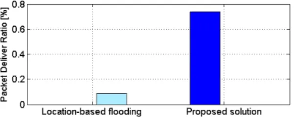
3) Scenario III: As we describe above, the location-based flooding scheme is based on the assumption that better link quality can be gained by a shorter communication distance. However, in a great number of scenarios, all kinds of obstacles exist between sensor nodes and the sink. In this scenario, in Figure 4, we establish an obstacle between the node 2 and the sink. The communication performance from location-based flooding and our proposed flooding scheme is compared.
V. EVALUATIONRESULTS ANDANALYSIS
This section describes the simulation results, followed by the analysis of the simulation results.
A. Scenario I
Figure 3 illustrates two types of PDRs of different routing protocols under Rayleigh fading. The result proves that our solution achieves higher PDR than those conventional routing protocols. The reason is that packets are routed via one preselected path by conventional routing schemes. Since the probability of transmission failure via one path is relatively high under the Rayleigh fading model, all PDRs from the conventional routing schemes are below 40%. However, be-cause our proposed solution allows packets to be transmitted to the sink through several paths under the condition of forwarding criteria, the transmission diversity is achieved to improve the reliability. The PDR from our proposed solution is slightly higher than location-based flooding, since both of
TABLE II
AVERAGE AND MAXIMUM END-TO-END DELAY FOR SCENARIOI Routing protocol Ave. end-to-end delay Max. end-to-end delay
AODV 0.260 ms 4.07 ms DSR 0.256 ms 8.30 ms DYMO 0.232 ms 3.98 ms Location-based flooding 0.171 ms 0.495 ms Proposed scheme 0.188 ms 0.496 ms TABLE III
RECOVERY TIMES FOR VARIOUS ROUTING PROTOCOLS
Routing protocol Recovery time Other parameters AODV 39.7 sec Hello interval: 30 sec
19.9 sec Hello interval: 15 sec
DSR 290.1 sec
DYMO 35.4 sec Hello interval: 30 sec 28.4 sec Hello interval: 15 sec Location-based
flooding
0 sec
Proposed scheme 0 sec Weight updated once
these schemes apply broadcasting method to forward pack-ets. Moreover, P DRdeadline from three conventional routing
protocols are less than P DRoverall, since these conventional
routing protocols do not guarantee that packets arrive at the destination within the deadline. Even if the outdated packets finally arrive at the sink, these packets are considered to be useless. By our proposed solution, outdated packets are discarded on-the-fly in intermediate nodes, so P DRdeadline
and P DRoverall are the same from our proposed scheme.
Average and maximum end-to-end delays are shown in Table II. Average end-to-end delays from all routing schemes are below 0.5 second. However, when we investigate the maximum end-to-end delays from three conventional routing schemes, the latency is much higher than the deadline. It clearly proves that the conventional routing schemes forwards packet at the best effort behavior, which is not suitable for industrial real time communications. Conversely, both the location-based flooding and our proposed flooding have the maximum end-to-end delay less than the deadline.
B. Scenario II
Packets from the nodes 13 are forwarded by the intermediate node 4. If the node 4 is shut down for some reason, a new path should be established by the routing protocols as soon as possible. The time is spent on finding a new route, named as recovery time, from different routing protocols is shown in Table III. It is obvious that the DSR scheme consumes the longest time to establish a new route due to the lack of route updated messages. The recovery time from AODV and DYMO is much shorter, depending on the time interval of hello messages. Although less recovery time can be achieved by shortening the hello interval, much more control messages as overhead are required in IWSNs, which leads to more network resources consumptions. By our proposed solution, weight-updated messages are only transmitted in the beginning of
Fig. 4. Network Topology with Obstacles
Fig. 5. Packet delivery ratios of Scenarios of node 2 for scenario III
the simulation. A seamless transition in the event of topology change can be achieved. It proves that the interval of weight-updated messages can be set much longer than the one of hello messages of the conventional routing schemes. Due to the similar mechanism, the location-based flooding scheme achieves the same recovery time as our proposed solution. C. Scenario III
As shown in Figure 4, an obstacle between the node 2 and the sink introduces huge attenuation of wireless signal. The optimum solution for the node 2 to send packets to the sink is to explore transmission paths via other intermediate nodes, rather than directly transmitting data to the sink. Figure 4 demonstrates that the node 2 is assigned a higher weight value W = 149.3, automatically discovered by the weight-updated mechanism. Thus, all packets from the node 2 are forwarded by other two nodes with smaller weight values, namely the node 7 with W = 74.9 and node 3 with W = 78.9. However, this cannot be achieved by the location-based flooding scheme. According to the result in Figure 5, a significant improve-ment is gained by our proposed solution, compared with the location-based flooding scheme. In industrial environment, due to a great number of metallic surfaces and machineries, this simulation scenario is quite common in reality. Therefore, our proposed solution is able to server much better for IWSNs than the location-based flooding scheme.
VI. CONCLUSIONS ANDFUTURE WORK
In this work, we point out the drawbacks of existing WSN routing protocols which make them not suitable for
IWSNs. A reliable and flexible RSS-based routing protocol is proposed. By flooding weight-updated messages from the sink according to the proposed algorithm, every node is assigned a weight value. Then packets from sensor nodes are forwarded to the sink according to forwarding criteria. The simulation results show a significant improvement of both transmission reliability and latency, compared with the conventional routing protocols and achieve similar communication performance as the location-based flooding scheme, but with the avoidance of installation difficulties. Our solution also provides a seamless transition in topology changes. Finally, the simulation result proves that our solution significantly outperforms the location-based flooding scheme in scenarios where obstacles exist.
Currently, more than one sink in IWSN and packet forward-ing from the sink to end nodes are not supported. Therefore, the future work in this area should consider fully support of multiple sinks and downlink RSS-based routing scheme.
REFERENCES
[1] (2010) Hart 7 specification, http://www.hartcomm.org/. [Online]. Available: http://www.hartcomm.org/
[2] Industrial society of automation, http://www.isa.org/.
[3] Shenyang institute of automation, http://www.industrialwireless.cn/. [4] T. Watteyne, A. Molinaro, M. Richichi, and M. Dohler, “From manet
to ietf roll standardization: A paradigm shift in wsn routing protocols,” Communications Surveys Tutorials, IEEE, vol. 13, no. 4, pp. 688 –707, quarter 2011.
[5] T. Melodia, D. Pompili, and I. Akyildiz, “On the interdependence of distributed topology control and geographical routing in ad hoc and sensor networks,” Selected Areas in Communications, IEEE Journal on, vol. 23, no. 3, pp. 520 – 532, march 2005.
[6] M. Hamdi, N. Essaddi, and N. Boudriga, “Energy-efficient routing in wireless sensor networks using probabilistic strategies,” in Wireless Communications and Networking Conference, 2008. WCNC 2008. IEEE, 31 2008-april 3 2008, pp. 2567 –2572.
[7] M. Marina and S. Das, “On-demand multipath distance vector routing in ad hoc networks,” in Network Protocols, 2001. Ninth International Conference on, nov. 2001, pp. 14 – 23.
[8] S.-J. Lee and M. Gerla, “Split multipath routing with maximally disjoint paths in ad hoc networks,” in Communications, 2001. ICC 2001. IEEE International Conference on, vol. 10, 2001, pp. 3201 –3205 vol.10. [9] S. Han, X. Zhu, A. Mok, D. Chen, and M. Nixon, “Reliable and
real-time communication in industrial wireless mesh networks,” in Real-Time and Embedded Technology and Applications Symposium (RTAS), 2011 17th IEEE, april 2011, pp. 3 –12.
[10] J. ˚Akerberg, M. Gidlund, and M. Bj¨orkman, “Future research challenges in wireless sensor and actuator networks targeting industrial automa-tion,” in IEEE 9th International Conference on Industrial Informatics (INDIN’11), July 2011.
[11] F. Barac, J. Akerberg, and M. Gidlund, “A lightweight routing protocol for industrial wireless sensor and actuator networks,” in IECON 2011 - 37th Annual Conference on IEEE Industrial Electronics Society, nov. 2011, pp. 2980 –2985.
[12] S. Bhatti, J. Xu, and M. Memon, “Clustering and fault tolerance for target tracking using wireless sensor networks,” Wireless Sensor Systems, IET, vol. 1, no. 2, pp. 66 –73, june 2011.
[13] K. Akkaya and M. Younis, “A survey on routing protocols for wireless sensor networks,” Ad Hoc Networks, vol. 3, pp. 325–349, 2005. [14] J. ˚Akerberg, M. Gidlund, F. Reichenbach, and M. Bj¨orkman,
“Mea-surements on an industrialwireless hart network supporting profisafe: A case study,” in IEEE Conference on Emerging Technologies and Factory Automation (ETFA’11), Sept. 2011.
[15] D. Sexton, M. Mahony, M. Lapinski, and J. Werb, “Radio channel quality in industrial wireless sensor networks,” in Sensors for Industry Conference, 2005, feb. 2005, pp. 88 –94.