Postadress: Besöksadress: Telefon:
Extended Junction Based Source Routing
Technique for Large Mesh Topology
Network on Chip Platforms
Usman Mazhar Mirza
Master of Science Thesis 2011
Extended Junction Based Source Routing
Technique for Large Mesh Topology
Network on Chip Platforms
Usman Mazhar Mirza
This exam work has been carried out at the School of Engineering in Jönköping University in the subject area Electronics. The work is part of the university’s two-year Master of Science programme.
The authors take full responsibility for opinions, conclusions and findings presented.
Examiner: Shashi Kumar
Supervisor: Shashi Kumar and Rickard Holsmark Scope: 30 credits (D-level)
Abstract
Network on Chip (NoC) has been proposed as a scalable and flexible interconnect infrastructure for communication among hundreds of cores on a core-based System on Chip. Routing algorithm affects the communication performance of a NoC. Therefore, many researchers have proposed different routing techniques in their work. Source routing, with many advantages over distributed routing, is very suitable for NoC platforms but has a serious drawback of overhead for storing the path information in every packet header. A technique called Junction Based Routing (JBR) was proposed to overcome this limitation of source routing. In JBR, either the packet reaches the destination directly, or reaches a junction from where it picks up the path information for on-ward path towards the destination. However, JBR has few drawbacks such as increased packet latency due to the delay involved in fetching the new path information from junction nodes, increased path length overhead using minimum number of junctions and deadlocks while even using the deadlock free routing algorithms.
In this thesis we proposed a technique, called Extended Junction Based Routing (EJBR), to address the limitations of JBR. EJBR reduces the packet latency for the communicating pairs of nodes involving multiple junctions. We are using three virtual channels to avoid deadlocks and to make communication from junction to junction faster we are reducing the delay at intermediate routers among them by skipping routers pipeline stages. There are many interesting issues related to this approach. We discuss and solve three important issues related to EJBR, namely, number and position of junctions, junctions network topology and path computation for efficient deadlock free routing. A simulator has been developed to evaluate the performance of EJBR with simple source routing and JBR. We also developed a tool in MATLAB to find the efficient junctions network topology and to compute the paths for deadlock free routing. The results of simulations show that the performance of EJBR is better than JBR for few routing algorithms in terms of latency and throughput.
Keywords
Networks on Chip (NoC), System on Chip (SoC), Routing Algorithms, Source Routing, Junction Based Routing (JBR), Extended Junction Based Routing (EJBR), Packet Switched Networks, On Chip Communication, Core Based Design.
Acknowledgements
I take this opportunity to express my gratitude and deep regards to my supervisor Professor Shashi Kumar for his exemplary guidance, monitoring and constant encouragement throughout the course of this thesis. The blessing, help and guidance given by him time to time shall carry me a long way in the journey of life on which I am about to embark.
I also take this opportunity to express a deep sense of gratitude to my second supervisor Rickard Holsmark for his help, valuable information and guidance in modifying the SystemNoC simulator, which helped me in completing this task through various stages.
I am obliged to all of my teachers, for the invaluable knowledge provided by them in their respective subjects. I am grateful for their support during the period of my study.
Lastly, I thank Almighty, my parents, wife, brothers, sister and friends for their constant encouragement without which this assignment would not be possible.
Contents
1 Introduction ... 1
1.1 SYSTEM ON CHIP (SOC) ... 1
1.1.1 Core Based Design ... 1
1.2 METHODS FOR INTERCONNECTING THE CORES IN SOC ... 2
1.2.1 Point-to-Point Interconnections ... 3
1.2.2 Bus-Based SoC ... 3
1.2.3 Network on Chip (NoC) ... 4
1.3 NOC-BASED SOCDESIGN ISSUES ... 5
1.3.1 Topology ... 6
1.3.2 Routing Algorithms ... 6
1.3.3 Protocols ... 7
1.4 THESIS OBJECTIVES AND TASKS ... 7
1.5 DELIMITATIONS ... 8
1.6 RESEARCH METHOD ... 8
1.7 THESIS LAYOUT ... 8
2 Theoretical background of NoC ... 9
2.1 NETWORK ON CHIP ... 9
2.2 NOC:TERMINOLOGIES AND CONCEPTS ... 10
2.2.1 Layered Communication Architecture ... 11
2.2.2 Network Topology ... 12
2.2.3 Switching Techniques ... 13
2.2.4 Network Diameter ... 15
2.2.5 Path ... 15
2.3 MAIN COMPONENTS OF NOC ... 15
2.3.1 Resource Network Interface (RNI) ... 15
2.3.2 Router ... 16
2.4 BUFFERS AND VIRTUAL CHANNELS ... 17
2.5 CLASSIFICATION OF ROUTING ... 18
2.5.1 Deterministic Vs. Adaptive Routing ... 19
2.5.2 Source Vs. Distributed Routing ... 19
2.5.3 Static Vs. Dynamic Routing ... 20
2.5.4 Minimal Vs. Non-Minimal Routing ... 20
2.5.5 Application Specific Routing ... 20
2.6 DEADLOCK AND LIVELOCK ... 20
2.7 TURN MODEL BASED DEADLOCK-FREE ROUTING ALGORITHMS ... 22
2.8 EVALUATION OF NOC ... 26
2.8.1 NoC Simulator ... 26
2.8.2 Performance Parameters ... 26
2.8.3 Traffic Types ... 27
3 Junction Based Routing: an Overview ... 28
3.1 INTRODUCTION TO JUNCTION BASED ROUTING (JBR) ... 28
3.2 ANALYTICAL ANALYSIS OF DISTRIBUTED,SOURCE AND JUNCTION BASED ROUTING FOR NOC 30 3.2.1 Routing Overhead ... 31
3.2.2 Bandwidth Utilization ... 32
3.3 ISSUES IN JUNCTION BASED ROUTING ... 34
3.3.1 Number and Positions of Junctions ... 34
3.3.2 Number and Positions of Junctions with Zero Path Length Overhead ... 34
3.3.3 Deadlocks in Junction Based Routing with Minimum Number of Junctions ... 38
4 Extended Junction Based Routing ... 40
4.1 BASIC IDEA OF EXTENDED JBR ... 40
4.2 TWO IMPLEMENTATION OPTIONS FOR EJBR AND THEIR COMPARISON ... 41
4.2.1 Comparison of EJBR with Long Range Physical Links Insertion and with Virtual Channels ... 44
4.2.2 An Illustration of EJBR with Virtual Channels ... 45
4.3 FLITS FORMAT IN EJBR ... 49
4.4 STEPS FOR DESIGNING NOC WITH EJBR ... 51
4.4.1 Generation of Junction Network Topology ... 51
4.4.2 Routing Algorithm Selection, Path Computation and Path Encoding ... 51
4.4.3 Performance Evaluation of Extended Junction Based Routing (EJBR) ... 52
4.4.4 Router Design ... 52
5 Junction Network Topology ... 53
5.1 OBJECTIVE AND CONSTRAINTS ... 53
5.2 ALGORITHM FOR TOPOLOGY GENERATION ... 54
5.3 RESULTS ... 57
6 Performance Evaluation of EJBR ... 61
6.1 MESH TOPOLOGY NOCSIMULATOR FOR SBR,JBR AND EJBR ... 61
6.1.1 Simulator Inputs and Other Hard-Coded Parameters ... 63
6.1.2 Simulator Outputs and Performance Parameters ... 65
6.2 SIMULATION RESULTS ... 65
6.2.1 Comparison of EJBR with SBR, JBR for Various Routing Algorithms ... 66
6.2.2 Performance Comparison of Various Routing Algorithms for EJBR ... 76
6.2.3 Advantage of Smaller Routing Information ... 79
7 Conclusions and Future Work ... 81
7.1 CONTRIBUTIONS AND RESULTS ... 81
7.2 LIMITATIONS ... 83
7.3 FUTURE WORK ... 83
8 References ... 85
9 Appendices ... 87
9.1 PERFORMANCE COMPARISON OF VARIOUS ROUTING ALGORITHMS FOR JBR ... 87
1 Introduction
The number of components or cores of a system that are integrated on a single chip are increasing rapidly and results in efficient communication requirements among different cores or components of the system. This thesis focuses on techniques for the efficient communication among different cores of a system on chip. In this chapter, we will discuss different ways to interconnect the cores of a System on Chip. We will also list the objectives and issues solved in this thesis.
1.1 System on Chip (SoC)
The improvement of Very Large Scale Integration (VLSI) technology in the past few decades resulted in millions of transistors on a single silicon die. The growth of number of transistors is increasing rapidly and with current technology it is possible to fabricate one billion transistors on a single silicon die. The improved technology and higher capacity resulted in implementation of the complete electronic system on a single chip and integration of different components of the systems on the same chip. This results in more complex designs. Thus to reduce this complexity, System on Chip (SoC) came into existence which provides a platform to interconnect large number of components or Intellectual Property (IP) blocks on a single chip.
1.1.1 Core Based Design
A core is an already designed component or block that can be used to develop a system on chip and has its own particular functionality. A SoC can be developed by designing own cores or components or by reusing already designed Commercial of the Shelf (COTS) cores. We can integrate those cores on a single chip to develop a SoC [1][2]. Mostly SoC are designed using IPs or cores to reduce the time to market of the product and to increase the reuse of the components [1]. Integrated system on a single chip results in reduced size and increased performance of the system. Some examples of cores are special purpose blocks, general-purpose processor cores, DSP cores, memories, I/O controller blocks etc. As we increase the number of cores or IPs it becomes harder to interconnect and integrate them on a single chip and it increase the complexity of design. Some issues involved in SoC development are to reduce power consumption and to reduce design complexity [3]. An example of core based SoC is “System-on-Chip for 2.4 GHz ZigBee/IEEE 802.15.4 with Location Engine” [4], developed by Texas Instruments which has 8051 microcontroller core, location engine, IEEE 802.15.4 compliant 2.4 GHz transceiver, 128KB Flash, 8KB RAM etc. (see Figure
Figure 1-1 System-on-Chip for 2.4 GHz ZigBee/IEEE 802.15.4 with Location Engine (Photo from TI website).
1.2 Methods for interconnecting the Cores in SoC
There are many different methods for interconnecting the cores in a SoC. Examples of methods for interconnecting the cores are Point-to-Point Interconnections, Buses and Network on Chip (NoC) [5][6]. Choosing a good method for interconnection of cores in a SoC is a very important design issue. A better method for interconnection of cores reduces the energy consumption, complexity and manufacturing cost of the system.
By choosing a better method for interconnection, the performance of the system can be improved by decreasing the communication delay between the cores and by increasing the average throughput [7][8].
1.2.1 Point-to-Point Interconnections
Point-to-Point Interconnections and Shared Buses were mostly used for interconnecting the cores till very recently [5]. Point-to-Point Interconnections among different cores is shown in Figure 1-2.
Figure 1-2 SoC based on Point-to-Point Interconnection Infrastructure. This method has drawbacks such as low reusability and scalability and under utilization of network resources. Large routing area is required because of large numbers of wires between each communicating core. This method also becomes inefficient with the increase in number of cores. However, if the numbers of cores are small then SoC designs based on this method are likely to give highest possible performance [6].
1.2.2 Bus-Based SoC
SoC based on shared bus communication infrastructure is illustrated in Figure 1-3. The idea behind this method is that the communicating cores share the wires. Many existing Systems on Chip are Bus-Based SoC [3].
In Bus-Based SoC there is a component called bus arbiter that decides the grant of bus access to a particular core. In this method of interconnecting the cores, bus access time increases with the increase in number of cores. The longest distance between two communicating cores determines the communication delay in this method of communication.
Figure 1-3 SoC based on Shared Bus Communication Infrastructure.
In this method the cores/resources compete for the access of bus and bus arbiter grants the access of bus to the cores according to given set of rules/priorities. Also just two cores can transfer data to each other at the same time. There are also some advanced ways such as hierarchical, segmented and pipelined buses that makes the communication in bus-based systems better than the normal bus-based systems. The bus-based interconnections work well with less than 8 cores/resources in the system. It is suitable for the systems where cores/resources as sources are few and cores/resources as destinations are in majority [9].
1.2.3 Network on Chip (NoC)
SoC based on Network on Chip (NoC) infrastructure is illustrated in Figure 1-4. For multicore system on chips, NoC has emerged as a dominating paradigm. In NoC communication infrastructure the cores are interconnected using a network of routers. Packet-switched communication is used for communication of cores in NoC infrastructure. Many researchers have proposed many NoC architectures in literature [8][9]. Two most important aspects to differentiate NoC architecture are routing algorithm and network topology. Like other networks, router is the most important component in SoC based on NoC infrastructure. Router forwards the
incoming packets either to destination core or to next router in the routing path from source to destination.
Figure 1-4 SoC based on NoC Infrastructure.
The protocols used in NoC are mostly adopted from general data network protocols but are the simplified versions of them. In NoC, we want the router design as simple as possible for small sized communication infrastructure.
1.3 NoC-Based SoC Design Issues
In this section we will discuss some issues in NoC-Based SoC Design such as Topology, Routing Algorithms and Protocols. Performance of a NoC depends mainly on these design issues.
1.3.1 Topology
Topology is one of the most important issue in the design of a NoC because the design of network router depends upon network topology. Network topology is described as the arrangement of different components (routers, links etc.) in the NoC. Different researchers in literature proposed many different topologies. We will discuss some of these topologies in detail in the next chapter. One of the most common network topology for NoC is Mesh topology and we will use it throughout in this thesis.
1.3.2 Routing Algorithms
Routing algorithms plays an important role in communication performance of a NoC. In literature routing algorithms have been divided in many different categories. We can categorize routing algorithms as source routing vs. distributed routing. In source routing, the complete routing path is embedded in the packet header and it is not possible to change the path once the packet leaves the source node. One drawback of this scheme is that it increases packet overhead because each packet must have the whole routing path information. Whereas in distributed routing, each router upon receiving a packet takes the routing decision and hence results in reduced packet overhead.
Another classification of routing algorithms in literature is deterministic vs. adaptive routing. In deterministic routing (also known as oblivious routing), the path is computed using the source and destination addresses only. In adaptive routing, different routing paths can be adopted depending upon the dynamic network conditions at runtime, which is not the case with deterministic routing algorithms. We will discuss more about routing algorithms and their classification in detail in next chapter.
For mesh NoC platforms, a master thesis [9] compared the performance of source routing with distributed routing and showed that the design of router is very simple for source routing as compared to distributed routing. It showed that source routing is likely to have advantages over distributed routing for small networks. Source routing was not performing well for large NoC platforms due to increased packet overhead. To overcome this drawback, a junction based routing (JBR) technique was presented for large NoC platforms in a master thesis in 2011 [10]. This thesis also compared the performance of JBR with source routing and showed that the performance of JBR in terms of throughput and latency is improved over source routing because now the header flit can carry the payload also instead of just the path information.
On the other hand JBR introduced some other problems such as increased overhead in terms of path length because using minimum number of junctions for mesh NoC the minimal paths cannot be used for packet transfer among many pairs of nodes in the network [10].
1.3.3 Protocols
Performance of NoC also depends upon Protocols used in NoC. Mostly the NoC communication protocols are the simplified protocols adopted from general data networks.
1.4 Thesis Objectives and Tasks
Junction based routing as we mentioned earlier cannot use the minimal paths for packet transfer among many pairs of nodes if we use minimum number of junctions and that results in increased overhead in terms of path length as compared to the source routing. This issue finally results in increased average packet latency for those pairs of nodes that cannot use the minimal paths. One solution is to increase the number of junctions, but as junction routers are more complex this increases the overall network cost. Therefore, a solution is required to decrease the average packet latency of those pairs of nodes that cannot use the minimal paths. There is no existing solution of the mentioned problem so far in the literature for JBR.
The main purpose of this master thesis is to design a new routing technique for large mesh NoC, called Extended Junction Based Source Routing Technique (EJBR), which will make the communication among junctions faster and results in efficient communication among the pairs of nodes in the network that cannot use the minimal paths and for those pairs of nodes that use multiple junctions for their communication and are far apart in terms of path length. The goal is to complete the theoretical work regarding this new technique and to work on evaluation and comparison of this new technique with existing techniques (Source Routing and Junction Based Routing). The evaluation will be simulation based and the simulator is designed in SDL language.
The thesis consists of the following tasks:
Ø Development of new Extended Junction Based Source Routing Technique for Large Mesh NoC and identify the contexts in which the new technique will perform better than the old ones.
Ø Perform the general and analytical analysis of the routing algorithms (distributed, source and junction based routing algorithms) and compare them. It is not a compulsory requirement of thesis.
Ø Compute all paths from sources to destinations for each pair of nodes for the new routing technique.
Ø Modification of an existing simulator to evaluate the new routing technique.
Ø Evaluation and comparison of new routing technique with source and junction based routing.
1.5 Delimitations
Similar to JBR, delay in junctions in EJBR is still more than simple router. The cost (in terms of area) of junctions and simple router is more than that of JBR and source routing because we have introduced virtual channels and each virtual channel requires extra input and output buffers on each router port. We can compensate these disadvantages by a good router and junction architecture design but it is not addressed in this thesis.
1.6 Research Method
Simulation-based experiments are used as our research method in this master thesis. We used two methods, literature review and interviews, for data collection and required background information for our work. Quantitative content analysis is used as methodology for data analysis and comparison of results.
1.7 Thesis Layout
In this chapter, we described different methods of interconnecting cores in a SoC. We discussed NoC-based SoC design issues and finally we discussed the objectives and goals of the thesis work. Next chapter presents the detailed background knowledge about the NoC paradigm and also discusses the related work already done in this area. In chapter 3, we illustrate junction based routing with examples and presents its comparison with source and distributed routing analytically. We also describe advantages and disadvantages of JBR. Chapter 4 defines new Extended Junction Based Routing Technique and its concepts. It presents two implementation options and their comparison and finally it discusses the steps for improved JBR. Fifth Chapter discusses the algorithm for junction network topology and its objectives and results. Chapter 6 presents the performance evaluation of new technique. The NoC simulator (designed in SDL language) is used for performance evaluation and results are presented and analysed for different routing algorithms. Chapter 7 concludes by mentioning the contribution and our proposal for the future work.
2 Theoretical background of NoC
In this chapter basic concepts about NoC will be discussed. Discussion will start with the introduction to the terminologies of NoC and the concepts borrowed from the communication networks. It will continue with describing the components of a NoC, switching techniques and classification of routing algorithms. The discussion will end with describing the performance parameters that are important to evaluate a NoC.
2.1 Network on Chip
Point to point interconnection/dedicated wires and bus-based SoC, both methods of interconnections have number of disadvantages such as both can be used only for interconnection of a few IP cores and are inefficient for high communication performance. Other disadvantages are that both methods have low scalability and are less reusable for new SoC designs. Because of these number of disadvantages researchers proposed a new method of interconnections, packet switched network on chip, for efficient communication among cores in a SoC [6][7][8][11][12]. Packet switched network communication infrastructure is shown in Figure 2-1.
Figure 2-1 SoC based on Packet Switched Network Communication Infrastructure.
In a NoC-based SoC, cores/resources transfer packets among them using a network of switches also called routers. Figure 2-2 shows a mesh topology NoC. In NoC-based SoC, a resource network interface is used to connect each resource with a router as shown in Figure 2-2. Data travels in form of packets from source core to destination core. These packets may traverse to multiple routers to reach their specific destinations in the network. In this design paradigm many pairs can communicate at the same time but it can affect the performance efficiency. NoC-based interconnection method is much more scalable and reusable than dedicated wires and bus-based SoC and thus it reduces the cost and time to market of the system. It reduces complexity of design and makes the testing and verification of the whole system easier because of the pre-routed wires [7][8]. A SoC based on 3X3 Mesh topology NoC is illustrated in Figure 2-2.
Figure 2-2 SoC based on 3X3 Mesh Topology NoC Infrastructure.
2.2 NoC: Terminologies and Concepts
Mostly the protocols used in NoC are the simplified versions of the communication protocols that are used in data networks. Similarly many concepts and terminologies used in NoC are adopted from data networks. We will discuss some network communication definitions and concepts that are applicable in NoC in the following subsections.
2.2.1 Layered Communication Architecture
Similar to general communication networks, the architecture used in NoC is layered communication architecture. Communication architecture is partitioned into different layers namely application layer, transport layer, network layer, data link layer and physical layer. Each layer performs its tasks independently. In NoC, mostly three layers are used i.e. physical, data link and network layer. Each layer in NoC performs different tasks independently (i.e. protocols). There are many advantages of layered communication architecture but there are certain overheads involved.
Now we will discuss some network communication terminologies in the following sub-headings.
Message
Message is the data to be moved from source core to the destination core. Its size can be fixed or variable and it is defined in the application layer. A message may consist of many packets.
Packet
A packet represents a data unit in the form of group of bits. It can be transferred from the source node to the destination node independently because the packet consists of all the data that is required for it to reach its particular destination from the source node. A packet normally is divided into two parts; header that contains the control and routing information and payload that contains the data. Sometimes packet has one more part as well that indicates the end of packet. Its size can be fixed or variable and can be partitioned down into smaller data units that are called flits.
Flit
Flit or Flow Control Digit is the group of constant number of bits (fixed size) that fits the storage resources (such as buffers) in the network switches.
Phit
Phit stands for Physical Transfer Digit. Its size is equal to link/channel width between two routers for data transfer. The size of Phit may be equal to Flit size.
2.2.2 Network Topology
Network topology is described as the arrangement of different components (routers, links etc.) of a network. Network topology is a very important in designing of a network router. Generally we can categories the topologies as regular or irregular topologies. There are many topologies that are proposed for NoC and some are shown in Figure 2-3.
In this thesis, we will use dimensional mesh topology. Because of its flat two-dimensional layout it is easy to implement it. The size of mesh is generally defined in the form of RXC where R represents number of rows and C represents number of columns in the network. Mesh is a regular topology and there are also other regular topologies such as cube and hypercube that are similar to mesh.
2.2.3 Switching Techniques
Switching techniques describe how data will move from input channel of the router to the output channel. Latency of the network mostly depends upon the used switching technique [13]. Common switching techniques used in NoC are circuit switching, store and forward, virtual cut-through and wormhole switching. Wormhole, virtual cut-through and store and forward are all packet switching techniques [3][7][8][9].
In circuit switching, before transmitting the data a physical path is established between source and destination nodes. The path remains established for the whole duration of communication and after the transmission of data the path is released. This technique is not flexible and reactive to traffic. Although this technique of switching ensures reliable communication, it results in underutilization of network resources. The performance of this technique is better than other techniques for real-time streaming applications.
Store and forward switching is also known as packet switching. In packet switching, data is transferred among nodes in the form of formatted packets. Different fields of packets are header, payload and some times terminator field. The packet’s header stores the routing and control information whereas real data to be transferred is stored in packet’s payload field. The packet’s terminator field may contain end of packet information. The routing path in packet switching can be changed while the packet is in the way to its destination, hence the routing can be reactive to the traffic. A packet may traverse through number of routers in its way before reaching its destination node and the resources of network are assigned as the packet traverse in the network.
Store and forward switching has higher communication delay and it requires large buffer size in network routers equivalent to at-least one packet size because a whole packet is transferred from one router to the next and the packet can only be forwarded to the next router when it is completely received.
In virtual cut-through switching, the communication delay is less than store and forward switching but the buffer size requirements are same. The reason of reduced communication delay is that it is not required that complete packet arrives at intermediate routers and the router starts to forward the packet as the header arrives and the destination output channel is free. The reason of same large buffer size requirement is that if the required output channel is busy then the router needs to store the whole packet.
A packet is further divided into flits in wormhole switching before transmission. Hence, smaller input/output buffer sizes as compared to store and forward and virtual cut-through switching are required and hence the size of router is decreased. Normally, the packet is divided in three types of flits i.e. head flit, body flit and end flit as shown in Figure 2-4. The head flit(s) contain the control and routing information, body flits contain the payload and the end flit carries the payload and end of packet information. An example to demonstrate wormhole switching is shown in Figure 2-5.
To transmit data from a source node to a destination in wormhole switching, source node first transmits the head flit and then it transmit body and end flits that follow the head flit. When the head flit reaches the next routers in its way to destination, the routers check it and lock that path for the remaining flits of that packet. The remaining flits follow the path locked by head flit and travel in pipelined way in the network. Hence reducing the latency because the latency now is less dependent on the distance between the source node and destination node. The path is unlocked by the end flit when it traverses through the router. As the flits seem to move as a worm in the network thus the technique is named as wormhole switching. If a head flit cannot move further, then all the body and end flits remain blocked along the way to destination and keep on occupying the channels and switches. Maximum number of occupied switches can be equivalent to the number of flits of the packet. Because the other messages, travelling in the network, also wait for the release of resources occupied by these flits to move further, this situation increases the chances of deadlock [13]. This is a major drawback associated with wormhole switching.
2.2.4 Network Diameter
Network diameter is defined as the maximum of the shortest distance between all pairs of nodes in the network. For a MXN mesh network, the network diameter is (M+N-2) [10].
2.2.5 Path
A path for communication from source to destination is represented by the set of channels ordered according to increased traversal time as packets travel from source node to the destination node. Path length is equal to the number of channels from source node to the destination node. Number of different possible paths from one node to other node defines the path diversity. A network is more fault-tolerant if it has higher path diversity.
2.3 Main Components of NoC
Three main building blocks of a NoC are routers/switches, resource to network interfaces (RNIs) and links or channels. In the following subsections we will discuss about routers and RNIs. These building blocks are shown in a 3X3 mesh topology NoC presented in Figure 2-2. Links/Channels are shared in NoC based SoC architectures and cores/resources compete for them and routers. One of the challenges in NoC architecture is to achieve high resource utilization [3].
2.3.1 Resource Network Interface (RNI)
Resource Network Interface (RNI) in NoC based communication architecture is used to connect each resource/core with router/switch. The functionality of RNI is similar to the functionality of an ethernet card in a PC [14]. RNI receives
packets from resource/core (source node) and performs some tasks such as packet flitization and embedding routing information etc. Similarly after receiving flits from a router connected to destination node, it performs deflitization, buffering etc. RNI is divided into resource independent and resource dependent parts as illustrated in Figure 2-6. The resource dependent part of RNI depends upon many things such as control signals, I/O, address and data bus width etc. of each resource and hence it is different for different resources. The resource independent part of RNI is reused in the whole network because it does not need to be modified for different resources.
Figure 2-6 Resource Network Interface.
2.3.2 Router
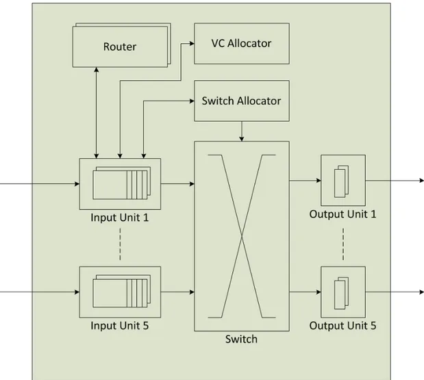
Router is very important component for SoC based on NoC communication infrastructure. Design of router should be very simple because with the increase in design complexity of the router the implementation cost is also increased [3][7][15]. A router, in a packet switched network on chip, forwards packets to the next router in the path or forwards packets to the destination core that is directly connected to it. Hence router switches the incoming packet from input channel/port to an output channel/port. In the routers designed for distributed routing, the output port is computed dynamically by running a routing algorithm or by using the routing tables (table based routers). In source routing, the complete routing path information is already stored in the packet header and hence the router read it from there. Router architecture for mesh topology NoC with virtual channels is shown in Figure 2-7. Generally the packets are buffered in input buffers before routing. Virtual channel allocator is used to allocate the desired virtual channel and it uses virtual channel identifier (VCI) field of packet header for this purpose. We will discuss the packet header format in detail later. A crossbar switch connects the input and output ports. The routing of packets is done simultaneously when there are no conflicts for output ports because the crossbar switch consists of many multiplexers.
Router block computes the desired output port using the implemented routing algorithm and it uses destination address stored in packet header for this purpose. Switch allocator allocates the switch to the input ports if the desired output ports are idle. Switch allocator use an arbiter to resolve the port conflicts using priority if there are conflicts for same output port.
Figure 2-7 Router Architecture for Mesh Topology NoC with Virtual Channels.
2.4 Buffers and Virtual Channels
In routers, input and output buffers are used to decrease the congestion effects. Input buffers are used to store the incoming packets that are waiting for the access of the desired output ports within the same router whereas output buffers are used to store packets that are waiting for the access of next router’s input ports. Buffers consume a lot of energy [15].
A virtual channel virtually splits a single physical channel into multiple channels and virtually provides multiple paths for a packet to be routed [7]. Because each virtual channel has an associated buffer so a virtual channel is nothing but a buffer that is associated with the respective virtual channel (VC). The working of virtual channels is illustrated in Figure 2-8.
For instance, if there is just one physical channel, if the packet B from node 1 which has to take turn towards south at node 2 is blocked, then the packet A from node 1 which has to go straight or take turn towards north at node 2 will also remain blocked until the packet B moves further. If there are two virtual channels, then packet A from node 1 which has to go straight or take turn towards north at node 2 can use the second virtual channel and move further even the packet B is still blocked at node 2 (shown in Figure 2-8). Hence the latency is reduced and throughput is increased using the virtual channels. Deadlocks can also be avoided using the virtual channels as well; difficult and interesting task is to find the minimum numbers of virtual channels to avoid deadlocks for a particular topology.
Figure 2-8 Illustration of Working of Virtual Channels.
2.5 Classification of Routing
We use routing algorithms to find the path(s) from one node to other nodes in the network. The path(s) can be selected such that the overall average latency is minimum and the network load is balanced properly. Thus, the performance of network depends upon the routing algorithm. The cost of router in terms of area and power consumption is reduced using simple routing algorithms [3][7][8][9]. We can classify routing in NoC in many different ways. Most commonly used classes of routing algorithms are:
• Deterministic Vs. Adaptive Routing • Source Vs. Distributed Routing • Static Vs. Dynamic Routing
• Minimal Vs. Non-Minimal Routing • Application Specific Routing
2.5.1 Deterministic Vs. Adaptive Routing
In deterministic routing algorithms, also known as oblivious routing algorithms, the complete path between any pair of nodes is computed in advance by using the source and destination addresses without considering the state of network. Deterministic routing algorithms determine the fixed paths whereas multiple paths are possible in adaptive routing algorithms. In adaptive routing, dynamic network conditions such as congestion and faulty links are considered to select a path. Adaptive routing algorithms can result in deadlocks and collisions [16]. Adaptive routing algorithms can be divided in fully adaptive and partially adaptive routing algorithms. Partially adaptive routing algorithms restrict some paths for communication, whereas in fully adaptive routing algorithms, all paths between any pair of nodes are possible for communication. Partially adaptive routing algorithms are very simple than fully adaptive routing algorithm and hence it is easier to implement them as compared to fully adaptive routing algorithms.
2.5.2 Source Vs. Distributed Routing
In source routing, all the routing information is embedded in the packet header before the packet transmission and the path information cannot be modified once the source node has transmitted the packet. Because all the packets contains the entire path information, therefore the packet size is increased but the router design for source routing is simple. In distributed routing, a router either computes the output channel dynamically by running a routing algorithm, or selects the output channel by using the routing table that is stored in router. In distributed routing, dynamic network conditions are considered to compute or select the path. The packet formats for both source and distributed routing is shown in Figure 2-9. We can see from Figure that packet header for distributed routing contains only the destination address. Where as, packet header for source routing contains the complete routing information (addresses of all the routers in its way to the destination node).
2.5.3 Static Vs. Dynamic Routing
In static routing, it is not possible to modify the routing path after the packet has been transmitted. In dynamic routing, the routing path is determined dynamically and hence it is possible to modify the path according to the network conditions.
2.5.4 Minimal Vs. Non-Minimal Routing
In minimal routing algorithms, just the shortest possible paths are used for communication. Whereas in non-minimal routing algorithms, shortest as well as longer distance paths are also used for communication. Some advantages of non-minimal routing are better load balancing and better fault tolerance as compared to minimal routing.
2.5.5 Application Specific Routing
Application specific routing algorithms are used for specialized applications. For some specific applications, we can estimate the communication profile of application and see which cores are communicating and in which volume they are communicating and which cores are not communicating at all. Hence, for the best performance of that particular application, application specific routing algorithms can be designed. One example of specialized application specific routing algorithm is APSRA [17].
2.6 Deadlock and Livelock
Deadlock is a process in which the packets are blocked in some routers in the network and do not move further and the delivery of packets is delayed forever. When number of packets wait for each other to release resources in a circular fashion then this situation can lead to deadlock. Because a packet in wormhole switching may hold buffers in many routers at the same time, hence possibility of deadlocks is more in wormhole switching technique than other switching techniques. An example of deadlock situation is given in Figure 2-10. Four source nodes S1, S2, S3 and S4 are trying to send packets to destination nodes D1, D2, D3 and D4 respectively at the same time. We can see from the Figure that the packets stopped to make progress when the packets from S1, S2, S3 and S4 reach D4 (2,2), D1 (1,2), D2 (1,1) and D3 (2,1) respectively. This is because there is clockwise cyclic dependency among the channels C2, C5, C8 and C11 as we can see in Figure 2-10. Hence the packets cannot make further progress in the network towards their respective destinations. This results in a deadlock situation, which may be resolved using special methods.
Resolving the deadlocks can be costly, therefore it is generally recommended to have deadlock free routing algorithms that guarantees that deadlock cannot happen. One solution for deadlock freedom is to avoid circular communication in channel dependency graphs [13][16]. Similarly, we can use pre-emptive communication and priorities to avoid deadlocks.
Figure 2-10 An Example of Deadlock Situation.
Livelock is a process in which packets keep on traveling in the network forever and never arrive at their destinations. Livelock is the problem associated with non-minimal adaptive routing algorithms. An example of livelock situation is given in
Figure 2-11. Packet from node (1,0) to (4,0) followed the shortest path till node
(3,0) and found congested path/link between nodes (3,0) and (4,0) and hence took the east turn towards node (3,1) to use the non-minimal path. At node (3,1), packet found that the link between nodes (3,1) and (2,1) is the only link that is not congested; hence packet took south turn towards node (2,1). Similarly, at node (2,1) packet took west turn towards node (2,0). The packet keeps on traveling from node (2,0) to (3,0), (3,1), (2,1) and back to (2,0) in the similar fashion and it results in a livelock situation. Livelock is not the problem with non-adaptive routing algorithms.
Figure 2-11 An Example of Livelock Situation.
2.7 Turn Model based Deadlock-Free Routing
Algorithms
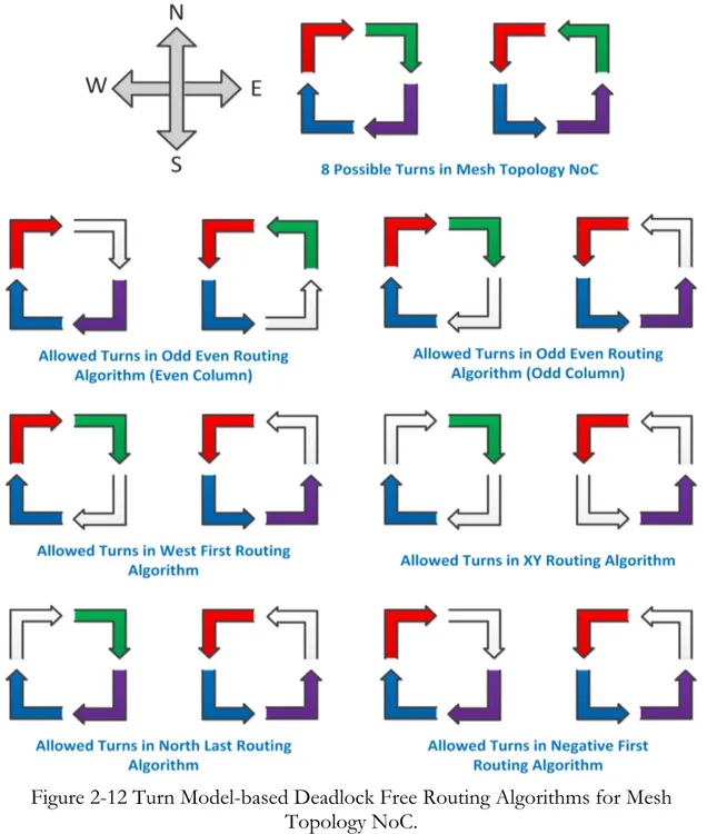
The performance of NoC heavily depends upon the routing algorithm. One of the important characteristics of routing algorithm is that it is deadlock free or not. We can use turn model and restrict some turns to design a deadlock free routing algorithm for N-dimensional mesh topology NoC [3][7][8]. In literature, there are many deadlock free turn model based deadlock free routing algorithms. In turn model based dead lock free routing algorithms, as illustrated in Figure 2-12, packets are restricted to take some turns while traveling in the network (restricted turns are represented by white colour). At least 2 turns should be restricted (1 clock wise, 1 anti-clock wise) for a deadlock free routing algorithm for a 2 dimensional-mesh topology network on chip [3]. In Figure 2-12, all eight turns of turn model for 2 dimensional-mesh topology NoC are presented. Below we will discuss some of the turn model based deadlock free routing algorithms.
In Odd-Even routing algorithm, packets are restricted to take East-South and East-North turns if the routers in mesh network are located in even column. If the routers are located in odd column in mesh network then packets are restricted to take South-West and North-West turns (see Figure 2-12). Odd-Even is a partially-adaptive routing algorithm and provides more even distribution of adaptivity as compared to other routing algorithms [3][13].
West-First routing algorithm restricts South-West and North-West turns at any router in the mesh network (see Figure 2-12). This is also a partially-adaptive routing algorithm and it is more adaptive as compared to XY routing algorithm [3][13]. The degree of adaptiveness in it is much less evenly distributed than Odd-Even routing algorithm [18].
In XY routing algorithm, just half of the turns of turn model are allowed and rest of them are restricted (see Figure 2-12). It is static, deterministic dead lock free routing algorithm. In this routing algorithm, packets always travel along the X-axis or horizontally towards the destination and then travel along Y-axis or vertically to reach their destination.
North-Last routing algorithm restricts North-East and North-West turns in all routers in the network (see Figure 2-12). It means that if the packet requires travelling north along with other directions to reach its destination, then it should travel towards other direction first and at the end towards north. It is also a partially-adaptive routing algorithm.
Negative-First restricts East-South and North-West turns in all routers in the network (See Figure 2-12). It means that if the packet requires travelling to horizontal or vertical negative axis along with other directions to reach its destination, then it should travel towards that negative axis first and then towards other directions.
For mesh topology NoC, many other deadlock free routing algorithms are available [3][13][17].
Figure 2-12 Turn Model-based Deadlock Free Routing Algorithms for Mesh Topology NoC.
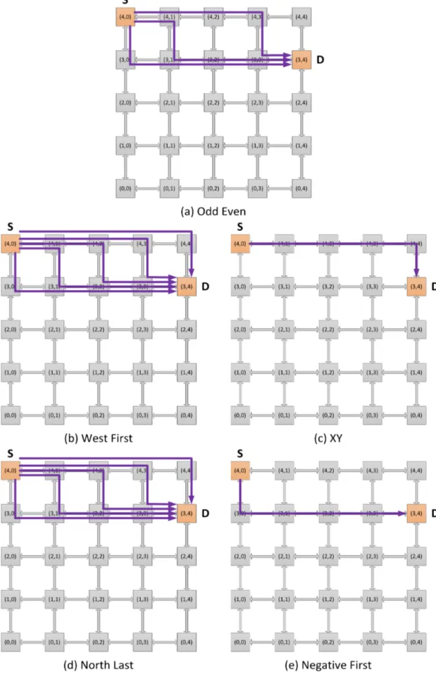
Allowed communication paths for source located at (4,0) and destination located at (3,4) in a 5X5 mesh topology NoC for all turn model based routing algorithms explained above are shown in Figure 2-13.
Figure 2-13 Allowed Paths in Different Turn Model Based Deadlock Free Routing Algorithms in a 5X5 Mesh Topology NoC.
2.8 Evaluation of NoC
2.8.1 NoC Simulator
Building hardware prototype for a NoC is a very time consuming and costly process. Hence to evaluate the performance of a NoC and model the behaviour of network, we use network simulators. For example, simulators are used to compare the performance of NoC for different routing algorithms.
Many simulators have been already developed to simulate NoC such as Noxim (developed in SystemC) and Network Simulator (NS2). Both simulators do not support source routing. SystemC, Java, C/C++, CAL, SDL etc. are some languages to model NoC simulators. Our research group in Jonkoping University used SDL language to model NoC simulator. This simulator supports both source-based routing and junction-based routing. We will modify the existing simulator and use it in this thesis to model the extended junction based source routing technique.
2.8.2 Performance Parameters
Below we will discuss some of the parameters that are important for performance evaluation of NoC.
Latency
Latency is the average delay of network to transfer payload from source to destination. Latency in NoC depends upon many factors such as routing delay, contention delay, channel occupancy and overhead involved in synchronizing routers packetization/depacketization and flitization/deflitization.
Throughput
Throughput is defined as the number of packets reached at destination per unit time.
Router Area
Router size/area also depends upon the routing algorithm used. The routing algorithm with smaller router size is more cost efficient.
Power Consumption
One more very important parameter for performance evaluation is power consumption. The routing algorithm with less power consumed by its corresponding router is considered better.
Packet Drop
Packet drop is the probability lost packets in the NoC. It is also used for performance evaluation.
Bandwidth
It is defined as the maximum rate of data transfer in the network. In-Order Packet Delivery
In adaptive routing algorithms where non-minimal paths are also used, packets can arrive out of order at destination routers and it requires extra computation at destination routers and it results in lower network performance. Hence, in-order packet delivery is one more important property for routing algorithms.
Link Load
It is an important parameter, as link load affects the network latency and latency increases with high link loads. If we consider bidirectional links then link load is the data travelling in network in each direction [9].
2.8.3 Traffic Types
The performance of NoC varies for a particular routing algorithm when we use different traffic patterns or types [18]. Different traffic types have been used by different researchers such as random (uniform random), hot spot, local, address bit reversal, shuffle, transpose and application specific traffic etc. for the evaluation of NoC [9][17][18]. In this thesis we will just use uniform random traffic for the performance evaluation of different deadlock free routing algorithms for extended junction-based source routing technique. In uniform random traffic, the source selects the destination randomly.
3 Junction Based Routing: an Overview
In this chapter, we present and discuss Junction Based Routing [10] in detail and illustrate its use in NoC. We also present its analytical comparison with Distributed Routing and Source Based Routing. Finally we discuss some of the challenges and issues in Junction Based Routing and advantages and disadvantages of JBR.3.1 Introduction to Junction Based Routing (JBR)
An important disadvantage of source routing is increased path information overhead in the header of each packet, which makes it a non-scalable technique as well. As the network size becomes larger, this disadvantage becomes worse. Junction based routing is a scalable technique to support source routing for large NoC platforms [10]. The idea is basically that, for long distance communications, send packets to the junction that is located nearest to the source node and then from there send them to the junction that is located closest to the destination node and finally from there to the respective destination node. In other words, in JBR we divide the whole path in different segments of shorter length. We restrict the path length to a constant number (For example Hop Count = 4 or Distance = 3) that makes it a scalable technique for source based routing.
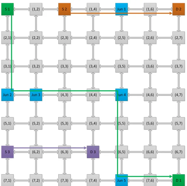
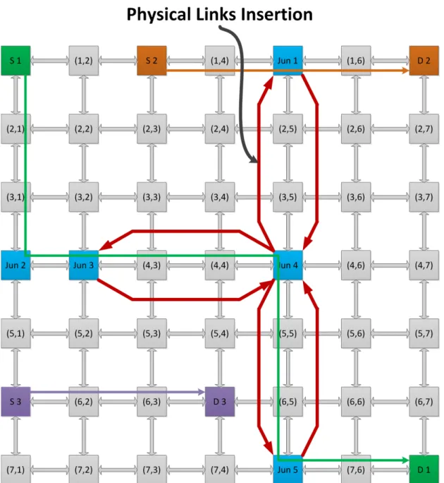
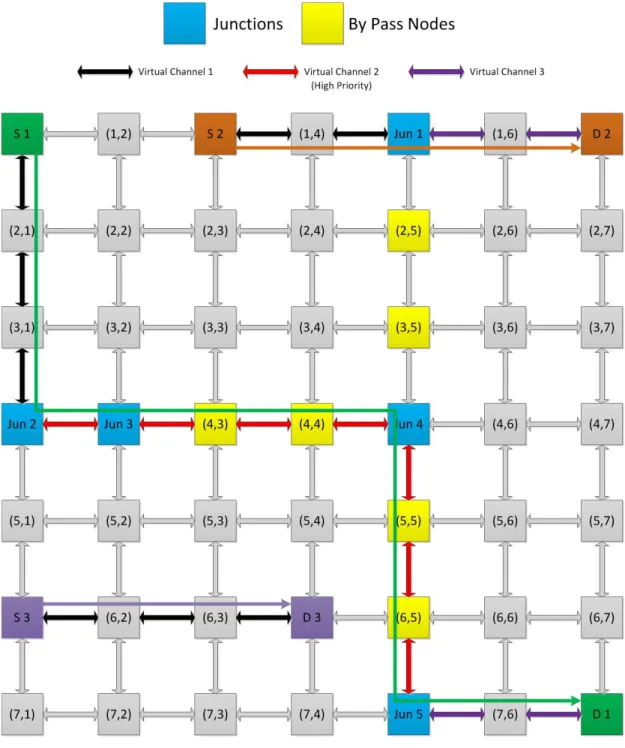
In Figure 3-1, an example to illustrate junction based routing for 7X7 mesh topology NoC is given. In source based routing (SBR) for 7X7 mesh NoC, path length is equal to Hop Count = 13 (Path information overhead is equal to 13*2 = 26 bits [9].), so any source node can send packets to any other destination node in the network. For the given example of JBR the path length is restricted to Hop Count = 4 (Path information overhead is equal to 4*2 = 8 bits [10].) and hence source nodes can only send packets to the destination nodes which are within the Hop Count limit of 4. Now we will consider the example shown in Figure 3-1 to explain junction based routing. We suppose S1, S2 and S3 are the source nodes located at locations (1,1), (1,3) and (6,1) respectively. D1, D2 and D3 are the destination nodes located at locations (7,7), (1,7) and (6,4) respectively. Similarly Jun1, Jun2, Jun3, Jun4 and Jun5 are the junction nodes located at locations (1,5), (4,1), (4,2), (4,5) and (7,5) respectively.
To send packets from S3 to D3, there is no need to use any junction because the hop count between both the nodes is equal to the maximum allowed path length (Hop Count = 4). To send packets from S2 to D2, just one junction Jun1 is required because the hop count between (S2, D2) is more than the maximum allowed path length but hop count between (S2, Jun1) and (Jun1, D2) is less than the maximum allowed path length. So S2 will first send packets to Jun1 (temporary destination) and then Jun1 will reload the path information in packets header and forward to the destination D2. To send packets from S1 to D1, multiple junctions Jun2, Jun3, Jun4 and Jun5 are required.
Figure 3-1 An Illustration of Junction Based Routing in 7X7 Mesh NoC.
A junction node can also work as normal node/router for forwarding packets to the next node/router. For example, if we consider node located at (4,4) as source node and node located at (4,6) as destination node, then Jun4 located at (4,5) will work as normal node/router instead of a junction. Because the hop count between the source and destination nodes is less than the maximum allowed path length, the packets have enough path information to reach the destination node so the Jun4 just forward the packets to the next router instead of reloading the path information in the packets header.
Packet formats for distributed, source and junction based routing for communicating pair (S1, D1) are shown in Figure 3-2 [10]. We can see that the packet header in JBR is very small compared to source based routing but still larger than distributed routing. The analytical analysis of this routing information overhead is performed in next section for all three kinds of routing techniques.
Figure 3-2 Packet Formats in Distributed, Source and Junction Based Routing [10].
3.2 Analytical Analysis of Distributed, Source and
Junction Based Routing for NoC
Analytical analysis of distributed, source and junction based routing in terms of routing overhead and bandwidth utilization is presented in the following subsections.
3.2.1 Routing Overhead
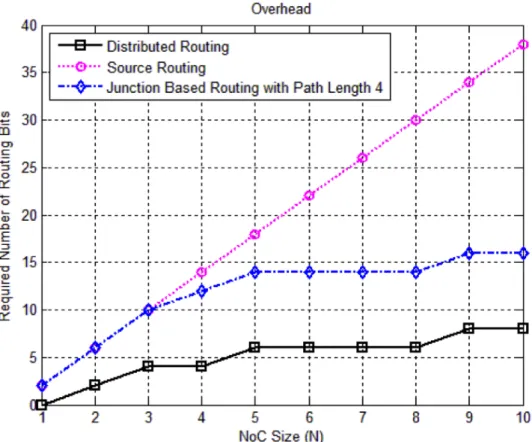
In Figure 3-3 a graph is shown in which the numbers of bits required for routing are plotted against NXN sized mesh topology NoC for distributed, source and junction based routing. Number of required routing bits for distributed routing increase logarithmically with the increase in network size because only destination address should be stored in the packet header. Whereas number of required routing bits for source routing increases proportional to the diameter of the network because complete route information is required in each packet header and hence results in large routing overhead [9]. On the other hand, partial route information (fixed bits for fixed segment length) and destination address should be stored in each packet header in case of junction based routing and hence routing bits required for routing increase logarithmically. Number of routing bits required to route data in NXN mesh NoC for distributed, source and junction based routing is given by the following formulae.
Number of required routing bits in Distributed Routing: 2 ∗ 𝑙𝑜𝑔!(𝑁)
Number of required routing bits in Source Routing: 2 ∗ (2𝑁 − 1)
Number of required routing bits in Junction Based Routing: min (2 ∗ 2𝑁 − 1 , 𝐾 + 2 ∗ 𝑙𝑜𝑔!(𝑁) ) where 𝐾 = 8 for segment length 4.
As we can see in Figure 3-3, the gap between graphs for distributed and source routing increases with an increase in the size of NoC whereas the gap between graphs for distributed and junction based routing remains constant (8 bits for segment length 4) when the size of NoC increases beyond N = 4. This difference in overhead if measured in terms of extra flits to be transmitted, remains very small or zero. Hence junction based routing in terms of routing overhead is much better than source routing.
Figure 3-3 Required routing bits for NXN sized NoC for Distributed, Source and Junction Based Routings.
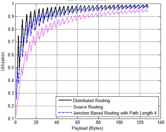
3.2.2 Bandwidth Utilization
The ratio of payload in bytes to be transmitted and the actual number of bytes to be sent carrying this payload is known as bandwidth utilization [9].
𝐵𝑎𝑛𝑑𝑤𝑖𝑑𝑡ℎ 𝑈𝑡𝑖𝑙𝑖𝑧𝑎𝑡𝑖𝑜𝑛
= 𝑃𝑎𝑦𝑙𝑜𝑎𝑑 𝑖𝑛 𝑏𝑦𝑡𝑒𝑠 𝑡𝑜 𝑏𝑒 𝑡𝑟𝑎𝑛𝑠𝑚𝑖𝑡𝑡𝑒𝑑
𝐴𝑐𝑡𝑢𝑎𝑙 𝑛𝑢𝑚𝑏𝑒𝑟 𝑜𝑓 𝑏𝑦𝑡𝑒𝑠 𝑡𝑜 𝑏𝑒 𝑠𝑒𝑛𝑡 𝑐𝑎𝑟𝑟𝑦𝑖𝑛𝑔 𝑡ℎ𝑖𝑠 𝑃𝑎𝑦𝑙𝑜𝑎𝑑
We assume fixed size flit of size 32 bits or 4 bytes (Data is transferred in form of flits when wormhole switching is used). In case of distributed and junction based routing, we assume that head flit can carry maximum 2 bytes and 1 byte of payload respectively. In case of source routing, we assume that head flit does not carry any payload. Let “P” be the payload to be transmitted in bytes then based on assumptions we made, actual number of bytes to be transmitted carrying this payload “P” in case of distributed, source and junction based routing is given by the following formulae.
Actual No. of bytes required in Distributed Routing: 4; 𝑓𝑜𝑟 𝑃 = 1,2 4 + 4 ∗ (𝑃 − 2)
Actual No. of bytes required in Source Routing: 4 + 4 ∗ (!!)
Actual No. of bytes required in Junction based routing: 4; 𝑓𝑜𝑟 𝑃 = 1 4 + 4 ∗ (𝑃 − 1)
4 ; 𝑓𝑜𝑟 𝑃 > 1
Bandwidth utilization is plotted in Figure 3-4 against the payload in bytes for distributed, source and junction based routing for a 7X7 mesh topology NoC. It can be seen that bandwidth utilization of junction based routing is much better than source routing and is almost equal to distributed routing. In all types of routing, the bandwidth utilization increases with the increase in payload. For larger payloads, utilization of both distributed and junction based routing becomes very close to each other and nearly equal to one, thus junction based routing is almost as good as distributed routing.
Figure 3-4 Bandwidth Utilization for Distributed, Source and Junction Based Routings in NoC.
3.3 Issues in Junction Based Routing
There are many interesting issues in junction based routing. Some important issues are finding number and positions of junctions in the network (addressed in [10]), finding number and positions of junctions with zero path length overhead and avoiding deadlocks when using minimal number of junctions. All these issues are discussed in detail in the following subsections.
3.3.1 Number and Positions of Junctions
When we limit the number of allowed bits to store the routing information in the header flit then minimum number of junctions are required to be placed in the network to make the communication possible among all the pairs of nodes in the network [10]. The pseudo code of the algorithm for finding minimum number of junctions and all possible configurations of their positions for given network size N and hop count limit H is given in [10].
Table 3-1 shows some results of the algorithm (presented in [10]) to find minimum
number of junctions that are required for different sizes of mesh topology NoC with given hop count limit “H”.
Mesh Size Hop Count Limit (H) Number of Junctions Number of Configurations 3x3 2 3 2 5x5 4 2 6 7x7 4 5 691 8x8 5 4 261 10x10 6 4 309 16x16 10 4 59238
Table 3-1 Required Minimum Number of Junctions and Number of All-Possible Configurations of Their Positions for Different Mesh NoC Sizes and Different
Hop Count Limits.
3.3.2 Number and Positions of Junctions with Zero Path Length Overhead
One interesting issue in junction based routing is to find the number and positions of junctions with zero extra path length overhead. It is important to notice that when we use the minimum number of junctions in JBR then for communication of many pairs of nodes it is not possible to use the minimal distance paths.
In Figure 3-5 (a), it is shown that 2 (minimum number of junctions) junctions are required for 5X5 mesh NoC with hop count limit 4 that are located at locations (2,1) and (2,4). Suppose source is located at location (0,0) and destination is located at location (4,0). Minimal distance between source and destination in this case is 5 hops (using SBR) but when we use JBR using minimum number of junctions then minimal distance between source and destination is 7 hops because packets has to go through the junction located at location (2,1). Hence packets have to go through 2 extra hops in this case. We can compute the extra path length overhead using JBR for all pairs of nodes using the following formula:
𝐸𝑥𝑡𝑟𝑎 𝑃𝑎𝑡ℎ 𝐿𝑒𝑛𝑔𝑡ℎ 𝑂𝑣𝑒𝑟ℎ𝑒𝑎𝑑 = 𝐽𝐷!" − 𝐷!" ! !!! ! !!! 𝑁! 𝑁!− 1 Where:
N = Number of Nodes in a Row/Column in NXN Mesh Network. 𝐽𝐷!" = Minimal Distance between nodes “i” and “j” using JBR.
𝐷!" = Minimal Distance between nodes “i” and “j” using SBR.
(𝐽𝐷!" − 𝐷!") is the extra path length overhead between nodes “i” and “j” when
we use minimum number of junctions in JBR. ! (𝐽𝐷!" − 𝐷!")
!!! !
!!! gives
accumulated extra path length overhead for all pairs of nodes in the mesh network. Dividing accumulated extra path length overhead for all pairs of nodes with the total number of pairs of nodes (𝑁!(𝑁!− 1)) in the network provides
the average extra path length overhead.
We developed a program in MATLAB that computes the minimum number of junctions with zero extra path length overhead and all possible configurations of their positions for a given network size and hop count limit. The pseudo code of the algorithm for finding minimum number of junctions with zero extra path length overhead and all possible configurations of their positions for given network size N and hop count limit H is given on the next page. We keep on increasing the required number of junctions until we find the configuration of junction positions such that extra path length overhead using that configuration of junction positions becomes zero.
For 5X5 mesh NoC with hop count limit 4, the required number of junctions with zero extra path length overhead are 7 and all-possible configurations of their positions in the network are 54. Some of the possible configurations of junction positions are shown in Figure 3-5 (b).
Mesh Size Hop Count
Limit (H) Number of Junctions Configurations Number of
5x5 4 7 54 ALGORITHM Number_and_Positions_of_Junctions_with_Zero_Path_Length_Overhead (N, H, Junctions_Positions) { Result_Found = 0; Required_Extra_Junctions = 0; Number_of_Junctions_Configurations = 0;
Delete current Junctions_Positions from all nodes and store the remaining nodes into Remaining_Nodes.
WHILE (Result_Found == 0) DO {
Required_Extra_Junctions += 1;
FOR All_Combinations of (Remaining_Nodes, Required_Extra_Junctions) DO
{
Assume each combination as one of the possible configurations for the junctions with zero extra path length overhead.
Also assume New_Junctions_Positions = Selected combination of junctions + Junctions_Positions;
IF (New_Junctions_Positions is fully connected with path length <= H)
{
Compute extra path length overhead using New_Junctions_Positions.
IF (Extra path length overhead using New_Junctions_Positions == 0) { Result_Found = 1; Number_of_Junctions_Configurations += 1; Store New_Junctions_Positions to Final_New_Junctions_Positions. } } } }
RETURN Required_Extra_Junctions, Final_New_Junctions_Positions, Number_of_Junctions_Configurations;
Figure 3-5 Few Possible Configurations of Junction Positions for 5X5 Mesh NoC with Hop Count 4 and Zero Path Length Overhead.
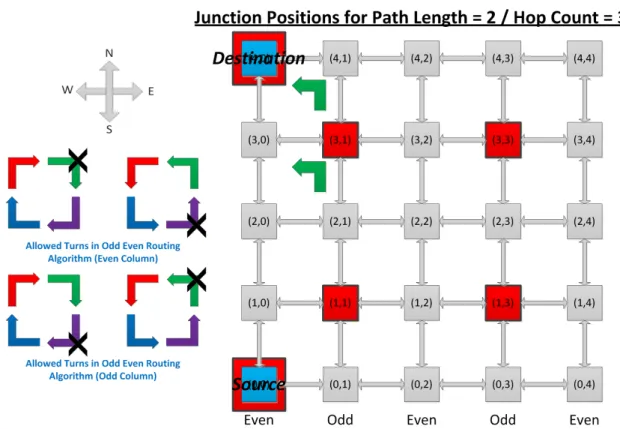
3.3.3 Deadlocks in Junction Based Routing with Minimum Number of Junctions
When we use minimum number of junctions that are required in the network to make communication possible among all pairs of nodes then used dead-lock free routing algorithm remains no more dead-lock free. This is a very serious issue with JBR that is illustrated in Figure 3-6. In the example odd-even deadlock free routing algorithm is used in 5X5 mesh NoC with hop count limit of 3. We suppose that we are allowed to just use the minimal paths for routing of packets. Suppose source is located at location (0,0) and destination is located at location (4,0) then two junctions are required for packets transfer from source to destination which are located at locations (1,1) and (3,1). In the particular example, using minimal paths, north-west turn is required either at node (3,1) or at node (4,1) for packets transfer from junction located at (3,1) to destination as shown in Figure 3-6. Both the nodes (3,1) and (4,1) are located at odd-column in the mesh network and we know that using odd-even routing algorithm north-west turn is not allowed when the node/router is located at odd column of mesh network. But for transfer of packets from junction located at (3,1) to destination, north-west turn is must required when we use minimal paths. Hence odd-even routing algorithm will no more remain deadlock free when we use minimum number of junctions with minimal paths in JBR. Similarly, for other deadlock free routing algorithms, we can create the examples to illustrate that those algorithms are also no more deadlock free.
Figure 3-6 An Illustration of Deadlocks in JBR when Odd-Even (Deadlock Free) Routing Algorithm is used with Minimum Number of Junctions Required.