INTERNATIONAL DESIGN CONFERENCE - DESIGN 2018 https://doi.org/10.21278/idc.2018.0219
EXTENDED DESIGN ASSETS ENABLING
AUTOMATED TOOL DEVELOPMENT AS A PART
OF A PRODUCT PLATFORM APPROACH
T. M. D. Heikkinen, J. Johansson and F. P. W. Elgh
Abstract
Product platform development is a well-established approach for reusing product knowledge in the form of geometry and its configuration rules and constraints. Explicitly defining all platform components is not always possible however. This is why a product platform approach where the processes of realising platform components also are supported is needed, instead of exclusively relying on their results. The work presented here works toward this, with a focus on automated tool development enabled by extending design assets from different tools.
Keywords: product platform, design automation, product families, model based engineering
1. Introduction
To meet the ever-increasing demand for more efficient and effective realization of products, a common approach is to reuse previous product and/or process knowledge (Heisig et al., 2010), both inside and in collaboration between the disciplines involved. Product platform development is a well-established approach for reusing product knowledge in the form of geometry and its configuration rules and constraints, commonly referred to as modules. It usually includes two main phases where first a platform is defined, which subsequently is used to realise product variants fulfilling the requirements within a specific market segment (Zha and Sriram, 2006). In cases where a product platform can be defined as a set of modules with predefined components and configuration rules, the realisation of a new product variant becomes a configuration task. Return of investing in platform development is achieved through standardisation of manufacturing processes and tools in such cases. Explicitly defining all module components entirely which meet the requirements for a specific market and time-frame might not always be possible, or even desired, however. One reason for this is if customer requirements are uncertain and the realisation of all components required to meet the potential customer requirements are not feasible. Developing some module components might require extensive product and production development and testing for each unique customer requirement. Enabling mass customisation by explicitly defining all possible module components then becomes implausible. This is why another, extended, product platform approach is necessary in these contexts where the processes of realising module components are supported, instead of exclusively relying on complete solutions. In this way, product variants can be implicitly defined as the results from specific processes, but only generated and evaluated when demanded. This entails new challenges however, such as assuring the process itself works within the bounds of product realization and can be used to meet the requirements within the targeted market segment.
In this paper, an effort is made in this direction by looking at production development aspects at a Swedish manufacturing company. The company operates in a context where future product requirements are
uncertain and highly coupled to the necessity to continuously adapt their products to market changes. These adaptions are done by the introduction of new module components. These module components are examples of how processes can be developed and standardized to implicitly define module components. The case company has for years put efforts to specify those underlying processes in close collaboration with the authors of this paper. Previous work has focused on automating product development activities, such as searching previous solutions (Johansson, 2012) and analysing safety factors (Johansson et al., 2015). Making sure the necessary production equipment can be efficiently developed had not yet been approached however, which of course is just as important. Therefore, the research work presented in this paper addresses the automation of tooling development as a way of implicitly defining tool-inserts to efficiently generate them on demand for a specific module component.
The paper is structured as follows: related work, automation context within the case company, approach employed, results, discussions and finally conclusions drawn.
2. Related work
A product platform has been defined in many ways, a shared element of them is however that they are a set of common objects used to efficiently realise and launch products (Meyer and Lehnerd, 1997). In other words, they are collections of objects which can be reused among products. When these reusable objects can be defined as pre-defined components, the task of realising a product which fulfils a customer's needs becomes one of pure configuration. Propagating constraints to achieve high levels of consistency when the number of variants grow, or constraints are applied between several domains, quickly makes this task highly complex or even computationally impossible within a reasonable time-frame. One way of dealing with this is to apply a procedure for the configuration task, where some domains are left implicitly defined until some related domains have been reduced.
Recent approaches in applying a product platform approach have included reusability of design aspects as well (André et al., 2017). In a way, these design assets can be seen as implicit definitions of some aspects of the product. However, since human creativity can be involved there are aspects of randomness and the process results can vary even though the input, design assets and tools are kept the same. Developing just one explicit platform component with them can be difficult to know in hind sight. This is because they might be high-level process descriptions with simple guidelines and heuristic rules. The knowledge involved when developing products (or components) can be categorised as product and process knowledge (Zha and Sriram, 2006). Product knowledge refers to the outcome from design activities and process knowledge to the activities themselves. In this paper we focus on the limitations of current product platforms to contain knowledge with respect to implicit component definitions, this could be seen as explicit process knowledge. To support re-usability of process knowledge, in order to efficiently and effectively realise platform components, the rationale behind them could be documented and guidelines to repeat them could be made as human and/or computer readable. To be able to find and effectively reuse these added support assets they could be attached to or otherwise linked to the features they relate to. The centralisation of CAD-models as an initial digitalised representation of the product geometry (Lundin, 2015) has made it a potential communication hub for many activities in multiple disciplines. Attaching or linking information through extensions to the CAD-models can be achieved in many ways; additional attributes, names, parameters, annotations, bundled features, programmed features, and additional geometry. These methods differ with respect to additional aids required, how comprehensive they are individually, and to which degree they can express actions to alter, add, or notify to different events (Heikkinen et al., 2018).
Model Based Enterprise (MBE) is a concept which has broadened the Model Based Definition (MBD) methodology (Miller et al., 2017a, 2017b). Instead of only using model based information as a way of replacing 2D drawings with 3D CAD-models, MBE has been described as a general way of supporting information consumption among any activity within an organisation. Many of the examples found revolve around annotating 3D-CAD models as a means of making the geometry more comprehensive and in this way make them more reusable (Trainer et al., 2016), stored inside or outside the actual CAD-model (Camba et al., 2014).
Annotations do not support modelling of process knowledge however, only the results from them as well as descriptions for how and why they came to be. The reasons why more elaborate extension
methods (as far as we have seen) are not used could be due to the restrictions in the interoperability between software, which is enabled through standardisation of the information (such as STEP AP204). Core Product Model2 (CPM2), as briefly described in (Fenves et al., 2008), is an interesting concept focusing on these shortcomings. CPM2 is a product model with the purpose to serve as a common data model supporting product lifecycle management and includes the outcome of design as well as the activities describing how the product information came to be as well as to some extent why it is conformed as it is.
Including design aspects within a product platform makes them similar to design repositories which can be defined as "intelligent knowledge-based design artifact modeling system used to facilitate the representation, capture, sharing, and reuse of corporate design knowledge" (Szykman et al., 2000). It has been noted that significant efforts are still required between design repositories and design automation modelling in CAD systems (Lyu et al., 2017) which this paper addresses in connection with tooling development.
3. Automation context within the case company
The company within which the automation took place is a global manufacturing company focusing on safe, easy-to-use and aesthetic products supporting an active lifestyle. Their products include transport equipment on cars, such as roof-racks, bike carriers and cargo carriers, and much more. Roof-racks are a central product on which both bike and cargo carriers are attached. They are comprised of two distinct parts; load bar and fixation system. Load bars are offered in four different variants and fixation systems vary with roof type (such as whether the roof has fixation points, flush railings, normal or wide railings, etc.). If the roof type is one without railings, a third component is necessary, an adaption kit, which varies with respect to roof-profiles, a unique geometric feature for each car-model.
The company's targeted market is 95% of all car-models for many years. Applying a conventional product platform approach would be possible if it was not for the incredible number of possible variations to the adaption kits. Since the kits are dependent on roof-profiles which vary for each new car-model released to the market, a well-established process has instead been defined to be prepared to develop and produce them as they are released and before customers need them (see Figure 1).
Figure 1. Overview of kit-development process
A Create Project Specification B Create Kit C Create Tools D Produce Start End B Retrieve Roof Profile A‐Market research B‐Product development C‐Production development D‐Production
In previous research projects at the company, focus has been on increasing the efficiency when searching for previous roof-profiles (Johansson, 2012) (to increase reuse of previous kit variants) and when performing crash simulations (Johansson et al., 2015) (for safety assurance). Efficiently realising production aspects is also an important part of the process which will be the focus of the current research. Adaption kits are comprised of two components, a footpad and bracket. At the moment, only the bracket is produced internally, and footpads are purchased, so the focus in the study presented here has been further narrowed to the bracket. It is a sheet-metal component which is formed in a press, which requires unique tool-inserts (pads and punches) and accompanying documentation for each adaption kit (see Figure 2). Since the process is performed several tenths of times a year, depending on the number of car releases, and the scope of requirements are quite well known in hind sight, automation fits this process well.
Figure 2. Product model constituents from product and production development
4. Automation approach
Initial steps towards automation of the tool development process included documentation analysis and qualitative interviews with domain experts. The focus for the automated process was put to range from receiving a tool order to developing the tool-inserts (punch and pad) as well initial documentation. This focus was put since these process steps are all performed within a digital environment and are confined by a single group in the organisation. Figure 3 shows an overview of the entire process, starting with getting an order through email followed by modelling and documentation efforts in CAD- and spreadsheet-software. Testing is then performed which can result in further refinements to the models. After identifying a general scope of the automation project, it was divided into six main phases: (1) Collect detailed information about the different tasks by recording and discussing the development of an actual order. (2) Formalise the process, including design assets and tools utilised using the recordings and notes taken. (3) Review automation capabilities and formalise a list of identified challenges. (4) Analyse the challenges identified and formalise a strategy to deal with them. (5) Codify, analyse and optimise. (6) Evaluate by recording the same activity again, supported with the developed automation system.
Figure 3. Tool-development activity overview, including tools utilised in each task
5. Results
Presentation of the tool development is structured according to the automation approach described above, steps (1) and (2) are integrated into Section 5.1 however.
5.1. Observe and formalize manual process (steps 1 and 2)
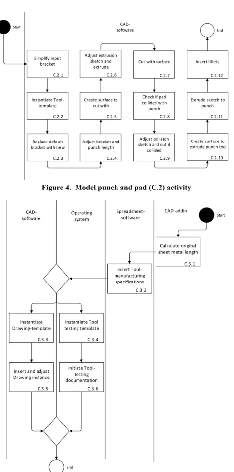
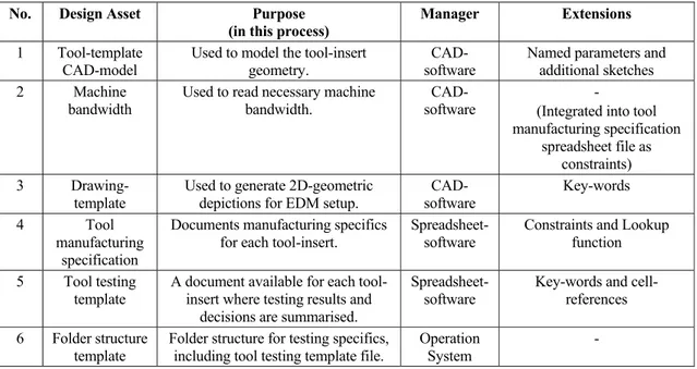
The manual process was recorded into a video and simultaneously discussed which took approximately 35min. This recording and the notes taken were then used as a basis for the formalisation of the activities, depicted in Figure 4 and 5. Within the process there were six design assets used each time; three managed by CAD-software, two by spreadsheet-software and the final one by the operation system. Their individual purpose and managing tools can be seen in Table 1 below. In short, there were four templates instantiated each time an order was received. They included a general tool model, a tool-insert drawing, a testing documentation spreadsheet and a testing folder structure. In addition, a tool-model was used to get the required sheet-metal bandwidth and a documentation file was used summarising all tool-inserts developed. C.1 Get order C.2 Model Punch and Pad C.3 Initial documentation C.4 Testing C.5 Documentation continued OK? C.6 Modify Punch and Pad Not OK Start End OK
Non‐digital Spreadsheet‐ CAD add‐in software
Email‐ software
CAD‐ software
Figure 4. Model punch and pad (C.2) activity
Figure 5. Initial documentation activity
C.2.2 Instantiate Tool‐ template C.2.3 Replace default bracket with new C.2.4 Adjust bracket and punch length C.2.5 Create surface to cut with C.2.6 Adjust extrusion sketch and extrude C.2.7 Cut with surface C.2.8 Check if pad collided with punch C.2.9 Adjust collision sketch and cut if collided C.2.10 Create surface to extrude punch too C.2.11 Extrude sketch to punch C.2.12 Insert fillets Start End C.2.1 Simplify input bracket CAD‐ software Start C.3.2 Insert Tool‐ manufacturing specifications C.3.6 Initiate Tool‐ testing documentation C.3.5 Insert and adjust Drawing instance End C.3.1 Calculate original sheet metal length CAD‐addin Spreadsheet‐ software CAD‐ software Operating system C.3.3 Instantiate Drawing‐template C.3.4 Instantiate Tool testing template
Table 1. Design assets and their specific purpose, tool-manager and extensions required for automation
5.2. Review automation capabilities and bring forth any challenges (step 3)
The tools utilised during the manual process (as illustrated in Figure 3 and 5) were three software (Email, CAD, and spreadsheet), one add-in to the software, and the operation system. All but the CAD-software add-in had extensive API's which enable automation processes that are persistent over time (e.g. software updates). That add-in was a third-party CAD-module specifically for sheet-metal forming purposes and would require the simulation of how a user interacts with the graphical user interface (e.g. sending short-commands or worse, simulating the mouse) to automate which is not a persistent way of automating software.
After reviewing the manual process and the automation capabilities a number of challenges could be identified, they were: (1) How should we deal with the "non"-automatable (at least persistently) tool? (2) How should we deal with the fluctuating modelling techniques applied to the received geometric model? (3) How should we deal with the uncertainties with spring-back effects? These are further described below. 5.3. Formalise a strategy to deal with challenges (step 4)
A strategy to deal with the above identified challenges was made by first analysing the underlying reasons for it followed by iteratively discussing and testing different approaches. Below is the analysis of the underlying reasons behind the challenges and the final strategy decided.
5.3.1. Challenge (1) How should we deal with the non-automatable (at least persistently) tool?
The tool which was difficulty to automatically manipulate effectively was the CAD-software add-in. This was used to measure the original (unbent) sheet length. To work around this a simple linear model, i.e.
∙ , was constructed relating the bended sheet length ( ) to the unbent (u) with a coefficient (k) which was estimated by running the add-in for several brackets. Initial tests (of about 10 brackets) showed a standard deviation of about 0,3mm with a maximum of 0,63mm, which was within the acceptable range. Later tests did however show larger deviation up to 2mm, which could be cause of concern.
5.3.2. Challenge (2) How should we deal with the fluctuating modelling techniques applied to the received geometric model?
Some of the process specifics was difficult to know in hind sight, such as how to simplify and otherwise alter the bracket geometry for tool-insert modelling. The bracket that is received is a depiction of the
No. Design Asset Purpose (in this process)
Manager Extensions 1 Tool-template
CAD-model Used to model the tool-insert geometry. software CAD- Named parameters and additional sketches
2 Machine
bandwidth Used to read necessary machine bandwidth. software CAD- (Integrated into tool - manufacturing specification
spreadsheet file as constraints)
3
Drawing-template Used to generate 2D-geometric depictions for EDM setup. software CAD- Key-words
4 Tool
manufacturing specification
Documents manufacturing specifics
for each tool-insert. Spreadsheet-software Constraints and Lookup function 5 Tool testing
template
A document available for each tool-insert where testing results and
decisions are summarised.
Spreadsheet-software
Key-words and cell-references 6 Folder structure
final form of the component which is not what the tool-inserts being developed are considering. There are a number of fillets and cuts which are sometimes removed since these are realised later in the production process. In addition, geometric dimensions associated with spring-back effects need to be changed as well. One reason for the difficulties in formalising how to simplify the bracket each time was the difference in modelling approaches when developing the bracket. There are at least four engineers modelling the brackets. To deal with this it was decided that some manual work would be required to simplify the model but also informing product development about the implications in efficiency of tooling development.
5.3.3. How should we deal with the uncertainties with spring-back effects?
Another rule which was difficult to specify in hind sight was what the spring-back effects would be, something which was evaluated each time by taking the experience gained from testing previous solutions in consideration. It was decided that this would be left as a manual step.
5.4. Codify, analyse and optimise (step 5)
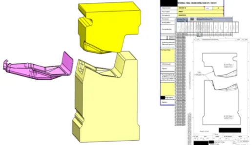
Since the process required some manual setup work using CAD-software it was decided that this would also become the main manager for the process. A CAD-macro was developed which was managed by a CAD add-in. The codification took about 4days to formalise 70% of the process, but approximately another 15days for another 15%. This was mainly because of the difficulties in formalising some of the geometry selection steps further down the process. The final 15% is made up of the setup process which was discussed above and also the positioning of two arrows in the drawing. They were not possible to position in an efficient way with the CAD-API and therefore left out. The positioning of the arrows took about 5seconds. Two examples can be seen below, Figure 6 shows a longer bracket and Figure 7 one where the pad and punch collided and an extension of the punch was necessary as well as the removal of a section of it.
Figure 6. Resulting tool-inserts (middle) and initial documentation (right) for a long bracket (left)
During the codification a number of extension were used, mainly for providing visible handles to the CAD-macro so that it could find and manipulate the correct parts. Table 1 shows a summary of all design assets and their individual extensions. A name convention was introduced and applied to parameters. The name convention allowed for adding key-words (marked by special characters within the name strings) so that sketch-parameters and drawing notes could be found and changed automatically. The name convention and key-words made the connection to the macro more visible and maybe ensured it is not altered or removed without consulting the effect on the macro as well. One design asset, namely
the machine bandwidth, could be added as a table of constraints to the manufacturing specification instead. Also, by using a spreadsheet internal look-up function it could give the bandwidth required directly when the unbent sheet-metal length was inserted. The final extension was cell-references where copies of the same information could be found, such as the bracket article number found on several of the spreadsheet sheets.
Figure 7. Resulting tool-inserts (middle) and initial documentation (right) for a short and high bracket (left)
5.5. Evaluate (step 6)
To evaluate the automated process, one of the domain experts was set out to receive two randomly selected tool orders, and the goal was to achieve the same (or improved) outcome as for the initially recorded manual process. The modelling of the first order was recorded and the second was not. It took approximately 5minutes to setup the model in both orders and an additional 12min for the first one and a little less for the second one. This is about half of the initial time. It was noted that the process had become a little less flexible however, names of components and the flexibility in changing modelling parameters had been affected.
6. Discussions
Automating tool-insert development to implicitly define tool-inserts for future platform/module components was shown to be practically possible to some extent and required the extension of design assets in the form of CAD-models and spreadsheet templates. How and why they were extended is discussed further in Section 6.1. Recording the task was possible since it only took about 30min, this made it easier to understand the detailed steps involved and most likely removed many questions due to memory loss. There are still some aspects which could not be formalised and the outcome from the process was not as flexible as wanted however. These aspects are also further discussed below, followed by future opportunities if the process was to be fully automated.
6.1. Extending design assets
To clarify what is put into the words "design asset" in this paper, they are used to describe a pre-defined digital artefact which is of value when executing a design process, separate from the entity performing the task (e.g. software or human). During the formalisation of the manual process of designing tool-inserts described in Section 5.1, a number of such objects could be identified, and they can be seen in Table 1. Identifying and utilising these design assets is thought to have made the automation project easier. To utilise the design assets within the automation application they were extended in different
ways however, this can also be seen in Table 1. As an example, a naming convention was established and applied to geometric parameters so that the script (CAD-macro) could find and alter it without mistaking it with another "randomly" generated parameter.
In previous research (Heikkinen et al., 2018) seven extension techniques for CAD-models were identified, they were: names, additional attributes, parameters, annotations, bundled features, programmed features, and additional geometry. Some of these are also applicable to other models, spreadsheets can be extended with notes (similar to annotations) and user-defined functions (similar to programmed features). In the automation of tool-inserts presented here the tool-template CAD-model (design asset no. 1) was extended using names and additional geometry (sketches). This was mainly done because these are information sources commonly manipulated at the company already. Any of the alternative techniques could have been used however which might have made it more secure and easier maintained. As was discussed in (Heikkinen et al., 2018) names cannot be used to model executable information which could make it dynamic with respect to changes made to it or other dependent aspects. Names are visible in for instance the CAD-feature tree but in contrast to annotations not in the graphical user interface and they quickly become incomprehensive when the amount of information needed to be stored inside becomes too large. Additional geometric elements can be visible in both the graphical user interface and the CAD-feature tree but bundled features or programmed features can be reviewed and references to the dependant entities can be customised. The added complexity and managerial aspects associated with these methods made them less interesting initially in the work presented here.
The drawing-template model (design assets no. 3) was extended with key-words, as an example all drawing annotations and textboxes where the kit article number was supposed to be inserted was replaced with the key-word "@KitNo" to make sure the script could identify all instances within strings that needed it. This could have also been done in an alternative way by adding new annotations or textboxes with unique names for instance. Using key-words changed the original template as little as possible and made it easy to manipulate and identify where the script was being affected however. Spreadsheet models (design assets 4 and 5) were extended with constraints (cells with new information), look-up functions, key-words, and cell-references. Using look-up functions and cell-references make the extensions dynamic to changes with respect to the dependant parts. However, since the references are one-way (in the sense that the constraints do not know which cells utilise them) and separated from the constraints they can become difficult to manage if changes are frequently required. This was not an issue in this context as these constraints are built into the machine from where they originate (sheet-metal bandwidths) and changes are not very likely.
6.2. Automation challenges
Automating the process of tooling-insert development starts when orders are received from email, but an initial manual setup is still required within the CAD-software partially due to the differences in modelling strategies within product development. Through formalisation of the tool development process, some of the relations have now been identified and communicated back to the design engineers (such as tangency between faces, specific dimensioning strategies etc.).
Ensuring that the models developed adhere to the standards required could be done post-development by formalising and implementing rules which need to be run successfully before sending an order to tool-development. Another approach which has been introduced is to work proactively and generating a bracket template which ensures that the geometry can be simplified automatically in the development of tool-inserts. Other reasons for the initial manual setup process is the prediction of spring-back, which is made by the production engineer taking the most recent experience from testing into consideration. Simulations had been reviewed previously, but not with good enough results. As the experience is further built maybe a general rule can be identified and applied however.
6.3. Output flexibility
Model flexibility is lost to some extent because the process knowledge contained in the automation-script is not instantiated and attached to the models it deals with. CAD-features (such as Extrusion, Revolve, Cut, etc.) are an example of process knowledge which is not only run, but also instantiated within the process context and saved with input, making it possible to also alter the input and rerun the
activity. Extending CAD-models with process knowledge is possible by using CAD-software capabilities such as rule-based systems or programmed-features. Rule-based systems, such as Knowledgeware within CATIA or Knowledge Fusion within Siemens NX, could be used for modelling process knowledge within their specific domains as well as for connection to spreadsheet-software. Macro-features, such as Custom Features within Siemens NX and Macro-features within Solidworks, can also be used to automate modelling activities within the CAD-domain and spreadsheet-software, but even more so by enabling the addition of COM-registered reference libraries. This means that activities performed in many other software can be included. Spreadsheet models could also be extended with process knowledge using user-defined functions. Instantiating and attaching the process knowledge would enable backtracking or reviewing of examples where the platform process knowledge was used, to which effect, and maybe for which reason (if documented correctly).
6.4. Opportunities
If the full process, from roof-profile data to the development of components, safety assurance through crash-simulations and tool-insert development, could be automated there are a number of interesting aspects to explore.
An exploration could be made of the roof-profile data extremes where maybe safety factors are affected, or production limitations are reached. In other words, the full design space could be modelled, and decisions could be made to investigate the limiting reasons if necessary and focus could be set at optimising manufacturing aspects or further expanding the scope. Thus, the product platform could be used very similar as to a conventional product platform. The product variants could be defined by describing which modules that should be included although it might not be possible to visualise the full component variation within the module containing the automation system.
Roof-profile trends could be analysed, and proactive actions could be applied to avoid possible issues in the future. If the sales-trends start moving toward a limitation of any product realisation requirement (safety or producibility in this case) then the initiation of a new product platform development project could be deployed to expand the scope for a future product family.
7. Conclusions
Being able to elicit the positive results from a product platform approach which includes design aspects requires a configuration procedure where some domains are kept implicitly defined through explicit process knowledge modelling. The company investigated in this paper manufactures products that need to be continuously geometrically adapted to new car-models. Keeping a constant outlook for upcoming car releases and proactively formalising and optimising the development process of the affected platform modules makes it possible to meet the requirements for the targeted market segment, and still keep internal production efficiency in check.
The presented automation of tooling development is one part of the companies increased development efficiency and was shown to be practically possible to a large extent in a persistent manner. The use of extended design assets as a foundation for automation projects might also be general and applicable in other design automation projects. The automation project of tool development at the company described in this paper can serve as a model for future automation projects within automated tooling development. To fully automate the process, further investigations are required with respect to the CAD-modelling strategies applied in previous steps and effective models for estimating sheet-metal spring-back. Ensuring output flexibility by exploring rule-based systems and programmed features is another interesting aspect which might also contribute to more transparency and exemplification of the design assets themselves.
Acknowledgement
The work has been carried out within the project ProAct (Platform Models for Agile Product Development: Building an Ability to Adapt), financed by the Region Jönköping County and Jönköping University.
References
André, S., Elgh, F., Johansson, J. and Stolt, R. (2017), “The design platform – a coherent platform description of heterogeneous design assets for suppliers of highly customised systems”, Journal of Engineering Design, Vol. 28 No. 10–12, pp. 599–626. https://doi.org/10.1080/09544828.2017.1376244
Camba, J., Contero, M., Johnson, M. and Company, P. (2014), “Extended 3D annotations as a new mechanism to explicitly communicate geometric design intent and increase CAD model reusability”, Computer Aided
Design, Vol. 57, pp. 61-73. https://doi.org/10.1016/j.cad.2014.07.001
Fenves, S.J., Foufou, S., Bock, C. and Sriram, D. (2008), “CPM2: A core model for product data”, Journal of
Computing and Information Science in Engineering, Vol. 8 No. 1, pp. 014501.
https://doi.org/10.1115/1.2830842
Heikkinen, T., Johansson, J. and Elgh, F. (2018), “Review of CAD-model Capabilities and Restrictions for Multidisciplinary use”, Computer-Aided Design and Application, Vol. 15 No. 4, pp. 509–519. https://doi.org/10.1080/16864360.2017.1419639
Heisig, P., Caldwell, N.H.M., Grebici, K. and Clarkson, P.J. (2010), “Exploring knowledge and information needs in engineering from the past and for the future - Results from a survey”, Design Studies, Vol. 31 No. 5, pp. 499–532. https://doi.org/10.1016/j.destud.2010.05.001
Johansson, J. (2012), “Combining Case Based Reasoning and Shape Matching Based on Clearance Analyzes to Support the Reuse of Components”, ASME 2012 International Design Engineering Technical Conferences and
Computers and Information in Engineering Conference, Chicago, pp. 603–610.
https://doi.org/10.1115/DETC2012-70631
Johansson, J., André, S. and Elgh, F. (2015), “Simulation Ready CAD-models as a Means for Knowledge Transfer”, Proceedings of the 20th International Conference on Engineering Design (ICED 15), The Design Society, Glasgow, pp. 195–205.
Lundin, M. (2015), Computer-Aided Product Development: Using Computer-Aided Technologies for Efficient Design Capture and Representation for Reuse, PhD thesis, Luleå tekniska universitet.
Lyu, G., Chu, X. and Xue, D. (2017), “Product modeling from knowledge, distributed computing and lifecycle perspectives: A literature review”, Computers in Industry, Vol. 84, pp. 1-13. https://doi.org/10.1016/j.compind.2016.11.001
Meyer, M.H. and Lehnerd, A.P. (1997), The Power of Product Platforms - Building value and cost leadership, The Free Press, New York.
Miller, A.M., Hartman, N.W., Hedberg, T., Barnard Feeney, A. and Zahner, J. (2017a), “Towards identifying the elements of a Minimum Information Model for use in a Model-Based Definition”, ASME 2017 12th
International Manufacturing Science and Engineering Conference, MSEC 2017 collocated with the JSME/ASME 2017 6th International Conference on Materials and Processing, Los Angeles, pp.
V003T04A017. https://doi.org/10.1115/MSEC2017-2979
Miller, A.M., Hughes, M.N. and Hartman, N.W. (2017b), “Evolution of the Model based Enterprise”, Proceedings
of CAD’17, Okayama, pp. 347–351. https://doi.org/10.14733/cadconfP.2017.347-351
Szykman, S., Sriram, R.D., Bochenek, C., Racz, J.W. and Senfaute, J. (2000) “Design Repositories : Next-Generation Engineering Design Databases”, IEEE Intelligent Systems, Vol. 15 No. 3, pp. 48–55. https://doi.org/10.1109/5254.846285
Trainer, A., Hedberg, T., Barnard Feeney, A., Fischer, K. and Rosche, P. (2016), “Gaps analysis of integrating product design, manufacturing, and quality data in the supply chain using model-based definition”, ASME 2016
11th International Manufacturing Science and Engineering Conference, Volume 2: Materials; Biomanufacturing; Properties, Applications and Systems; Sustainable Manufacturing,Blacksburg, Virginia, USA, June 27–July 1, 2016, pp. V002T05A003. https://doi.org/10.1115/MSEC2016-8792
Zha, X. F. and Sriram, R. D. (2006), “Platform-based product design and development: A knowledge-intensive support approach”, Knowledge-Based Systems, Vol. 19 No. 7, pp. 524–543. https://doi.org/10.1016/j.knosys.2006.04.004
Tim Matias Daniel Heikkinen, PhD Student Jönköping University, Product development Stjärnvägen 18, 55312 Jönköping, Sweden Email: tim.heikkinen@ju.se