2012:54
Technical Note
Initial Review Phase for SKB´s safety
assessment SR-Site: Geological
struc-tures and deformation zones, from site
investigation to safety assessment
SSM perspektiv
Bakgrund
Strålsäkerhetsmyndigheten (SSM) granskar Svensk Kärnbränslehantering
AB:s (SKB) ansökningar enligt lagen (1984:3) om kärnteknisk verksamhet om
uppförande, innehav och drift av ett slutförvar för använt kärnbränsle och
av en inkapslingsanläggning. Som en del i granskningen ger SSM konsulter
uppdrag för att inhämta information i avgränsade frågor. I SSM:s Technical
note-serie rapporteras resultaten från dessa konsultuppdrag.
Projektets syfte
Uppdraget är en del av granskningen som rör den långsiktiga utvecklingen
av bergmassan omgivande det tilltänkta slutförvaret. Detta uppdrag fokuserar
på att studera SKB:s strukturgeologiska modell. Frågor som berörs är hur
SKB har hanterat insamling och sammanställning av geologisk och
struktur-geologisk data samt hur dessa har använts vid design av förvaret och i
säker-hetsredovisningen. Strukturer i en bergmassa har stor betydelse för
grund-vattenflöde, skjuvrörelser och för utformningen av förvaret(hänsyn tagen till
deformationszoner och sprickor). En annan aspekt är de olika bergarternas
olika temperaturledningsförmåga som kopplar till förändrat avstånd mellan
enskilda deponeringshål. Frågor som berörs är också metodiken för
identifi-kation av deformationszoner, val av acceptanskriterier för
deponeringsposi-tioner samt den framtida karaktäriseringen av bergmassan på djupet.
Författarens sammanfattning
Den plats som Svensk Kärnbränslehantering AB (SKB) valt för djupförvaring
(ca 500 m djup) av använt kärnbränsle ligger i en berggrundsmiljö bestående
av prekambriska bergarter. Platsen för förvaret är Forsmark beläget vid norra
upplandskusten, 122 km norr om Stockholm. I ett geologiskt perspektiv
är Forsmark beläget i de centrala delarna av den Fennoskandiska skölden.
Upplands flacka landskap sammanfaller i stort med en utsträckt erosionsyta
bildad ovan vatten för mer än 540 miljoner år sedan. I själva verket har denna
yta återigen exponerats efter att ha varit täckt av palaeozoiska
sedimentberg-arter (yngre än 540 miljoner år).
Målområdet, den valda platsen tillräckligt stort för att inrymma förvaret,
är beläget i de centrala delarna av en storskalig veckstruktur med granitisk
berggrund (graniter och granodioriter). Veckstrukturen omges på vardera
sidan, mot nordöst och sydväst, av storskaliga, regionala deformationszoner
som mot nordväst skär varandra bildande en kil innehållande förvaret. Vid
förvaret varierar avståndet mellan dessa zoner från 2,5 till 3,5 km.
Berggrun-den på förvarsnivå kan även innehålla bergarter (basiska) som på grund av
deras lägre termiska ledningsförmåga kan påverka nyttjandegraden av
bergs-volymen. Detta eftersom denna egenskap hos de basiska bergarterna medför
behov av större separation mellan deponeringspositioner.
Själva förvarsområdet tudelas av en regional deformationszon (brant stående
och orienterad ONO, >3km lång) och ett område, vars utsträckning är 100 m
bred på vardera sidan om denna zon, tillåts ej att ingå i själva förvarsvolymen.
Utmed målområdets avgränsningar förekommer brant stupande
deforma-tionszoner orienterade i VNV, NV och ONO.
Berggrunden invid målområdet är med avseende på dess allmänna struktur
ej homogent. De ytliga delarna av berggrunden karaktäriseras av en förhöjd
täthet av flacka öppna sprickor och andelen öppna sprickor bland de brant
stupande sprickorna är även den förhöjd i förhållande till djupare nivåer.
Berg med öppna sprickor tilltar i mäktighet mot sydöst och innehåller även
flacka deformationszoner. Detta medför att sprickors egenskaper i hällar
funna i terrängen inte direkt återspeglar sprickors egenskaper på
förvarsni-vån. Markmagnetiska mätningar med hög upplösning indikerar att
berggrun-dens generella strukturmönster med avseende på brant stupande spröda
deformationszoner ej är homogent. Till exempel, den centrala brant stående
deformationszonen som är orienterad i ONO utgör en gräns med
huvudsak-ligen ONO orienterade deformationszoner sydöst därom och NO till NNO
orienterade strukturer i norr.
Den deterministiska strukturmodellen som beskriver målområdet uppvisar
ett relativt enhetligt mönster av lokala deformationszoner (1km≤length≤3
km); NO till ONO orienterade strukturer dominerar. Strukturer av denna
storlek får ej sammanfalla med kapselpositioner i förvaret. På grund av
osäkerheter i modeller kan läget på modellerade deformationszoner avvika
från dess verkliga läge i förvarsområdet. Modellen ger dock information om
mängden av deformationszoner. Utmed större sprickor (mindre
deforma-tionszoner och enskilda sprickor större än 150 m) kan sekundära rörelser, av
sådan storleksordning att de kan skada kapslar, utlösas av jordskalv. Sådana
strukturer får ej skära kapselpositioner. I djupa lägen är det dock svårt att
mäta den verkliga längden hos deformationszoner och sprickor. Emellertid,
förståelsen av strukturmönstret i förvarsområdet kan stödjas av modellering
med hög upplösning baserad på detaljerade geologiska data (borrhål och
tunneldata) och geo-fysikaliska undersökningar. Den statistiska fördelningen
av mindre deformationszoner (< 1 km) och sprickor i målområdet,
inklude-rande förvarsområdet, presenteras i stokastiska modeller (DFN).
Det saknas en diskussion om hur heterogenitet i rumslig fördelning av
indata (t.ex. borrhålslägen, riktningar och mätområde för de högupplösta
magnetiska mätningarna i relation till rumsliga förekomsten av grupper/set
av deformationszoner) påverkar den deterministiska modellen.
Sannolikhe-ten/risken för att tunna flacka deformationszoner förekommer på planerat
förvarsdjup är av stor vikt och borde lyftas fram mer.
Det hade varit fördelaktigt om skisser som beskriver geometrin (yttre och
inre) hos olika grupper/set av deformationszoner hade presenterats för att
stödja information given i tabeller. Visualisering är ett bra sätt att förmedla
och beskriva strukturgeologisk information.
Mängden insamlad geologisk och geofysikalisk information är mycket stor
och mängden skrivna rapporter är omfattande. All insamlad geologisk och
geofysikalisk fältdata är kvalitetsgranskad och lagrad i SKB:s databas SICADA.
Dock har några fel i kontrollerade data påträffats (felaktiga data t.ex. i
geofy-sikaliska borrhålsmätningar, och blandning av data, t.ex. i borrhålsradardata).
Kvaliteten hos utförda undersökningar och sammanställda rapporter är av
hög internationell standard. SKB:s platsundersökningar har utgjort underlag
för flertalet doktorsavhandlingar och publikationer i internationella
veten-skapliga tidskrifter samt presentationer vid internationella möten.
Emeller-tid behövs ytterligare studier, såsom alternativa modelleringar för att mer i
detalj utvärdera de resultat SKB erhållit, och för att bedöma om information/
data eller utförande behöver kompletteras.
Projektinformation
Kontaktperson på SSM: Lena Sonnerfelt
Diarienummer ramavtal: SSM2011-3633
Diarienummer avrop: SSM2011-4306
Aktivitetsnummer: 3030007-4019
SSM perspective
Background
The Swedish Radiation Safety Authority (SSM) reviews the Swedish
Nu-clear Fuel Company’s (SKB) applications under the Act on NuNu-clear
Acti-vities (SFS 1984:3) for the construction and operation of a repository for
spent nuclear fuel and for an encapsulation facility. As part of the review,
SSM commissions consultants to carry out work in order to obtain
in-formation on specific issues. The results from the consultants’ tasks are
reported in SSM’s Technical Note series.
Objectives of the project
This assignment is part of the review regarding the long-term evolution
of the rock surrounding the repository. The assignment focuses on the
structural geology model. Issues regarded are the handling and
inter-pretation of geology and structural geology data, and the use of data in
repository design and safety assessment. Geological features have impact
on groundwater flow, shear movements and on the design of the
reposi-tory (consideration to deformation zones and fractures). Another aspect is
the different thermal properties of different rock types which have impact
on the spacing between deposition positions. Issues regarded are also the
methodology for identification of deformation zones, selection of
accep-tance criteria for deposition positions and the planned future geological
characterization.
Summary by the author
The site selected by the Swedish Nuclear Fuel and Management Co (SKB)
for location of a deep geological repository, i.e. a storage for spent
nu-clear fuel at about 500 m depth in Precambrian metamorphosed rocks.
The location of the site is Forsmark at the northern coast of Uppland and
122 km north of Stockholm. In geological terms Forsmark is located in
the central part of the Fennoscandian Shield. The flat ground surface in
Uppland today mainly coincides with a vast surface formed by long-lasting
subaerial erosion more than 540 million years ago. Actually, the bedrock
surface is exposed again after being covered by sedimentary rocks of
Pala-eozoic age (younger than 540 million years).
The target volume, considered large enough to host a repository, is
loca-ted in the core of a large-scale fold where the rock is composed of
granite-like rocks (granites and granodiorites). The fold is bordered on each side,
i.e. to the northeast and southwest, by subvertical regional brittle
defor-mation zones (DZ) trending WNW and NW, respectively. The regional
zones form a wedge closing north-westwards. The separation between the
WNW and NW trending regional DZ varies from about 2.5 to 3.5 km in
the local site area. The bedrock at the planned repository level may also
contain rock (amphibolites) that may affect the utilization of the
availa-ble rock volume; due to lower thermal conductivity a larger separation of
canister positions is needed in amphibolites than in granitoids.
The actual target area is crossed by a steeply dipping regional DZ (>3 km)
trending ENE dividing the planned repository volume into two parts and
along such DZ no canister position closer than 100m is allowed. Along
borders of the target area there are steeply dipping regional DZ mainly
trending WNW, NW and ENE.
The general structural pattern in the bedrock is not homogeneous at the
target volume. The shallow part of the bedrock is characterized by
en-hanced density of open fractures dominated by gently inclined to
sub-horizontal fractures and also the proportion of open fractures among the
steeply dipping fractures are markedly higher compared to deeper levels.
The domain of open fractures increases in thickness south-eastwards. It
contains gently inclined DZ. This implies that outcrop fracture data do
not directly reflect fracture characteristics at the repository level. The
high-resolution ground magnetic measurements indicate that the general
pattern of steeply dipping brittle deformation zones (including also minor
deformation zones) is not homogeneous. For example, the central regional
ENE trending DZ forms a border; to the south mainly ENE trending DZ,
to the north a high proportion of NE to NNE trending DZ.
The deterministic structure model in the target area displays a relatively
regular pattern of local DZ (1km≤length≤ 3km); NE to ENE trending DZ
dominate. Such DZ are not allowed to intersect canister positions. The
actual location of DZ in the repository volume may, however, not fully
agree with the model DZ due to modelling uncertainties. On the other
hand, the model gives information about the general density of DZ. There
are also large fractures (minor DZ and single fractures; extending for more
than 300m) along which earthquake induced secondary slip may occur;
i.e. displacement that can distort a canister. Such DZ are not allowed to
intersect canister positions. It is difficult to measure the true length of
DZ and fractures at depth. However, high-resolution modelling based on
detailed geologic data (boreholes and tunnel data) supported by
geophy-sical measurements will strongly contribute to the understanding of the
structural pattern in the repository volume. The distribution of minor DZ
(<1km) and fractures in the target area, including the repository volume,
is presented in stochastic (DFN) models.
Missing is a discussion on how heterogeneity in spatial distribution of
input data (e.g. borehole location and orientation, and areal coverage of
the high-resolution ground magnetic measurements in relation to the
dif-ferent sets of deformation zone sets) effect the deterministic models. The
probability/risk for thin gently dipping DZ to occur at planned repository
depth and the potential to detect them prior to the excavation of the
repository level is crucial and could be enhanced.
It had been advantageous if sketches illustrating the geometry (external
and internal) of different sets of DZ were presented to support the
in-formation given in tables. Visualization is a good way of communicating
structure geological information.
The recorded geological and geophysical data is voluminous and the
number of reports written is exhaustive. All geological and geophysical
field data are quality checked and stored in SKBs database SICADA.
Ho-wever, some errors (distorted data, e.g. in a few geophysical borehole logs,
and mixing of data sets, e.g. in borehole radar files) have been found in
checked data.
The quality of performed investigation and reports are of high
internatio-nal standard. The SKB site investigations have formed the basis for several
Ph. D theses and publications in international scientific journals and
pre-sentations at international symposia. However, further studies are needed,
for instance alternative modelling, to evaluate the result gained by SKB in
more detail and to judge whether information/data or performances need
to be complemented.
Project information
2012:54
Author:Initial Review Phase for SKB´s safety
assessment SR-Site: Geological
struc-tures and deformation zones, from site
investigation to safety assessment
Sven A. Tirén
Geosigma / Uppsala, Sweden
This report was commissioned by the Swedish Radiation Safety Authority
(SSM). The conclusions and viewpoints presented in the report are those
of the author(s) and do not necessarily coincide with those of SSM.
Contents
1. Introduction ... 3
2. Description of the site, initial state – Geological description ... 7
2.1. General introduction – bedrock geology ... 7
2.2. Review, geological evolution ... 10
2.3. Overview, performed investigations ... 16
2.4. Overview, scales of geological models ... 17
2.5. Overview, base data – uniformity in data distribution... 19
2.6. Review, geological models – rock domains ... 23
2.7. Review, structure models ... 28
Structure model – brittle deformation zones... 33
2.7.1. Fracture minerals ... 40
2.7.2. Structure model – fracture domains ... 42
2.7.3. 2.8. Review, economic geology – natural resources ... 45
3. Geological concepts to support the layout criterion and strategies . 49 3.1. Terminology ... 49
3.2. Layout and the character of the bedrock ... 51
4. Summary and conclusions ... 59
1. Introduction
This review assignment is part of the Swedish Radiation Safety Authority’s (Strålsäkerhetsmyndigheten, in Swedish; SSM) Initial Review Phase of the Swedish Nuclear Fuel and Management Co’s (SKB) safety assessment SR-Site covering final disposal of spent nuclear fuel at the Forsmark site. The present review covers aspects on bedrock geology within the site area and its surroundings, with a special emphasis on structure geology.
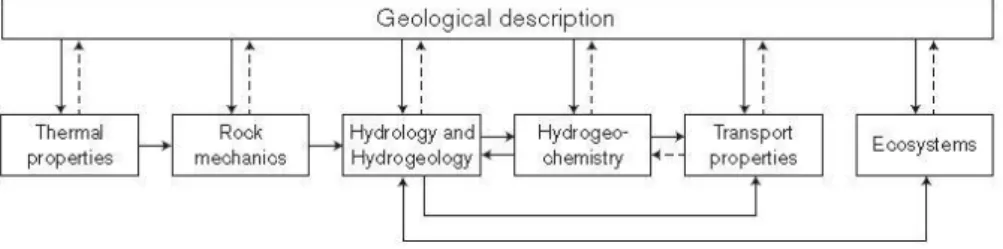
The characterization of a site is a multidisciplinary task and the geological character of the bedrock is of importance for the description/understanding of the full character of the site for deep geological disposal (Fig. 1.1).
Figure 1.1:The different discipline descriptions in the SDM are interrelated with several feedback loops and with geology providing the essential geometrical framework (TR-11-01; Fig. S-41).
Figure 1.2:The site descriptive modelling process may be split into various components (R-03-05; Fig. 2-1).
The integration of geoscientific information acquired within the site volume was first evaluated separately for each discipline. The outcome of this was subsequently compared and integrated with an interdisciplinary approach in order to achieve a site-descriptive model. The site investigations have been progressively and systematically performed and a sequence of gradually more refined site models have
1
References to SKB reports are given by the type of report /TR, R and P/ followed by the number of the report /e.g. SKB TR-11-01, i.e. in this case the first SKBTR report for 2011/. The type of reports gives also the level of the report, cf. Fig. 1-4. To find the reference either the page in the report (e.g. SKB TR-11-01 PXX) is given or the figure or the table (e.g. SKB TR-TR-11-01 Fig. XX/Table XX). SKB report are available at www.skb.se and go to publications. Other references are given by author/s and year. Cross-references have no external reference noted (e.g. Fig. XX).
been developed: version 0 (SKB R-02-32), version 1.1 (SKB R-04-15), version 1.2 (SKB R-05-18), stage 2.1 (SKB R-06-38), stage 2.2 (SKB R-07-45), stage 2.3 (SKB R-08-128, SKB R-08-64) and SDM-Site (SKB TR-08-05).
There is a large number of supporting reports (cf. references in reports listed above). Site investigation approaches and applied techniques were documented in a series of SKB reports. Descriptions of applied methods are given in method descriptions (SKB MD) and performances are given in activity plans (SKB AP). As the site characterization proceeded investigation techniques were improved. A good example is the high-resolution ground magnetic measurements performed at a relative late stage of the site investigations (2006-2007; SKB R-07-62). The results of these had a great impact on the structure model of the local site volume.
The presentation of performed investigations is systematically described and the language is Standard English. However, the number of reports is, as pointed out above, large. The data are thereby successively filtered as the site investigation proceeds and it can therefore sometimes be hard to trace all data. By necessity, basic information is repeated while some data is only to be found in earlier reports while several times repeated data my lose their references. The search for data on SKB’s homepage must be very specified unless not resulting in very large number of hits and to request primary data (see following section) need good information regarding what research has been performed or expectations regarding site characterization work.
Acquired site data are stored in the SKB data base SICADA (SIte ChAracterization DAtabase, mainly primary data) and models are stored in the SKB model data base SIMON (an Internet based data repository service; containing RVS / 3D models/ and GIS/ 2 D models -maps/). Data-freezes associated with each version/stage of the development of site descriptive models have been applied and secure that the data usage for each model is well defined and quality checked.
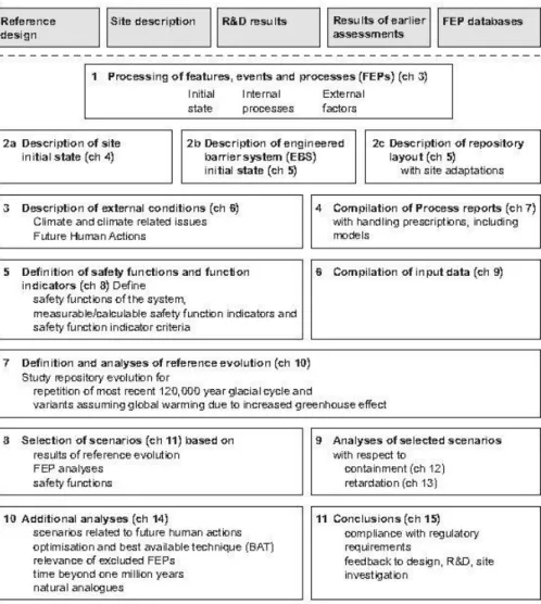
This review considers the following steps of the 11 steps (cf. Fig. 1-3) listed in the main SR – Site report (TR-11-01):
Step 2a Description of site, initial state (TR-11-01 sections 4-1-4.4); section 2 in this review document.
Step 2c Description of repository layout - with site adoption (TR11-01 section 5.2); section 3 in this review document.
The following SKB reports (or sections of reports if applicable) are included in this review assignment:
SKB TR-10-52, Data report for the safety assessment SR-Site, Sections 2, 6.2, and 6.3
SKB TR-10-48, Geosphere report, section 2, 4.1-4.4
SKB TR-08-05, Site description of Forsmark at completion of the site investigation phase, sections 1-3, 5-6and 11.
In many cases information from other SKB reports (SKB TR, SKB R and SKB P-reports; references mainly given by report number, cf. Fig. 1-4) are also used to support the review as well as data obtained from SKB data bases SICADA (site data) and the SIMON (site models)
.
Figure 1.3: An outline of the eleven main steps of the SR-Site safety assessment. The boxes at the top above the dashed line are inputs to the assessment. The chapters in the main report where the steps are further documented are also indicated (TR-11-01 S-6: references given in the figure refer to report SKB TR-11-01).
The geological description of a site has to provide information about the existence of available space for the location of a repository (cf. step 2 C in Fig. 1.2) and to provide other disciplines with basic information (cf. Fig. 1.2). To do this a set of thematic sub-models have been developed to describe the site:
Lithological model – rock domains; cf. section 2.6 below.
Structure model – brittle deformation zones, cf. section 2.7.1 below
Structure model – fracture domains, cf. section 2.7.3 below.
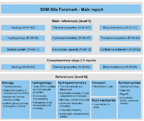
The first two types of sub-models are presented in two scales (R-06-38 P23-24): a regional scale block (165 km2 large and having a vertical extension to -2 100 m a.s.l.) and a local scale block (16 km2 large and having a vertical extension to 1 100 m a.s.l.). The local model is required to cover the volume within which the repository is expected to be placed, including accesses and the immediate environment.
Figure 1-4:SDM site main report and background reports on different levels produced during modelling stages 2.2 and 2.3 (TR-08-05 Fig. 1-9).
The following, section of this review (Chapter 2) considers the description of the initial character of the Forsmark site and its geological and structural character. The second chapter is divided into subsections discussing various topics regarding the site description: geological setting (2.1), followed by a section describing how information about the geological evolution is presented (2.2). The following subsections are more focused on the Forsmark site itself, the local model volume, and comprise discussions of performed investigations (2.3), scales of geological models (2.4), homogeneity of acquired site data (2.5).Then follow reviews of the geological models (2.6) and structure models and fracture minerals (2.7).In the last section of part 2 a review of the potential for mineral resources at Forsmark (2.8) is given. In the third part (Chapter 3), terminology (3.1) and geological concepts supporting layout criterion of a deep geological repository (3.2) are discussed. In the last part (Chapter 4) summary and conclusions are presented.
In addition to the description on the local scale (review here), a description is also devised for a much larger volume, the regional model, in order to place the local model in a larger context and to allow for a sensitivity analysis of, mainly, hydrogeological boundary conditions” (R-06-38 P23). The structure model describing fracture domains is only presented for parts of the local scale model. The regional scale model of the Forsmark area is only briefly discussed in section 2.2.
References to SKB reports are in this review not given in general descriptions of topics, i.e. in the introduction sections. At the end of each overview and review sections in Chapter 2 and at the end of Chapter 3 short comments on, for instance uncertainties, performance and complimentary works, are given.
2. Description of the site, initial state –
Geological description
The geological character of an area reflects its evolution and the characterization of an area is an interactive process as new information is progressively obtained during the characterization process. This implies that the approach of characterizing an area may be modified as the investigation proceeds, i.e. data with higher resolution may be needed and added, complimentary investigations to be adopted or that some performed investigations did not contribute successfully.
2.1. General introduction – bedrock geology
Location
The Forsmark candidate area is located within the sub-Cambrian peneplain and is a coastal lowland area in the northern part of Uppland (cf. Fig. 2-1 and 2-2), eastern Sweden. The bedrock is composed of metamorphosed and foliated Precambrian rocks. The degree of exposed rock inside the candidate area is low and outcrops are unevenly distributed, e.g. there are few outcrops in the central part of the target area NW of the lake Bolundsfjärden. The proportion of wet land is relatively high (25 to 35% in some of the sub-catchments) and the candidate area contains parts covered by sea water and lakes (Fig. 2-7b). The proportion of water-covered areas (lakes+sea water) in the target area or local model area is not found to be presented.
Geological setting of the Forsmark area
The Forsmark target area is located in a WNW-trending tectonic domain of Proterozoic age, composed by metamorphosed and foliated rocks and is regarded as part of a shear belt with an internal anastomosing network of ductile to ductile-brittle shears that outline large-scale tectonic lenses composed of apparently less deformed rock (cf. Figs. 2-1 and 2-4). The belt has a length of more than 1 000km and, at Forsmark, a width of about 35 to 40km. The amount of displacement along the discrete shears is not known and shears/faults have experienced later a tectonic, brittle reworking. Hence the bedrock in juxtaposed lenses may not be fully similar regarding rock type distribution and structural pattern. The Forsmark candidate area is located in the north-western part of a large scale shear lens.
Target area – target volume
In the target area, the bedrock types of interest for a potential deep geological repository are metamorphosed plutonic rocks (granodiorites-granites) in the north-western synformal part of a sheath fold (a tube like structure; in this case closing upwards), located between two regional shear zones, the Singö deformation zone and the Eckarfjärden deformation zone, conforming the north-western tip of a regional shear lens (cf. Fig. 2.4a and 2-4c). The boundary of the granitoids forms a reference structure as it has a well-developed magnetic banding. The questions are: a) the size of available volume for a repository (section 2.6, bedrock model) and b) how it can be effectively used for a geological repository (section 2.7.1, structure models, in combination with Paragraph 3, layout criterion and strategies)?
Geological modelling
The rock types and their three-dimensional distribution are well described in
deterministic models for rock domains (RFM /rock domain in Forsmark/, cf. section 2.6), which were outlined at a relatively early stage of the site characterization work. Later boreholes have confirmed the bedrock model and only minor adjustments have been made. The geological model forms the framework for the thermal, rock-mechanics, hydrogeological, hydrochemical and bedrock transport models.
A central assumption in the modelling of lithologies (rock domains, cf. section 2.6) is that rocks are extended parallel to the mineral lineation giving for example an aplitic granitic body in the north-eastern part of the fold a tubular form; dipping steeply south-eastwards in the synformal northern part of the sheath fold. On a larger scale, this involves that the geometry of the sheath fold (a fold that may form closed structures) enveloping the bedrock hosting the repository is controlled by the striation. This implies that a good control of the striation is important in the modelling the rock distribution in the Forsmark area.
The accumulated strain in the central granitoids is hard to assess as the rock may have been recrystallized synkinematically. However, the ductile deformation in the central granitoids increases outwards (achieves a magnetic banding, as a foliation) when approaching the regional ductile deformation zones at the borders of the candidate area. These ductile zones are the precursors of the NW to WNW trending Singö and Eckarfjärden brittle deformation zones bordering the Forsmark candidate area. Furthermore, the geological map indicates that the sheath fold is asymmetric and sheared along the Eckarfjärden deformation zone to the southwest. This is reflected by increased deformation (including also brittle deformation) in the western part of the target area (an inhomogeneity that may be considered in stochastic modelling of subordinate rock types and also fractures outside deformation zones).
The internal deformation in the granitoids is also revealed by the occurrence of minor lens-shaped bodies of amphibolites (meta-dolerites) lying concordant to the foliation and having their long axis parallel to the mineral lineation.
The high-resolution ground magnetic measurements, performed in the north-western part of the candidate area (i.e. the main part of the local model volume), show a more intricate pattern in the central granitoids than what is expressed in the geological map. The magnetic pattern reflects both primary inhomogeneities in the granitoids and the imprint of alteration and tectonic structures. The magnetic measurements may also reflect rock constituents not exposed in outcrops or found in boreholes. An example is a magnetic linear structure discordant to the foliation, having a more westerly trend, and interpreted as a basic dyke (no age suggested: youngest dolerites in the region are c. 1.4-1.2 Ga: 1Ga=109 years). The magnetic measurements also indicate low magnetic lineaments trending mainly NNE and out of five investigated lineaments one was found to represent late granitoids and pegmatites (see text below) while the other four are brittle deformation zones, i.e. the late granites have similar magnetic signature as brittle deformation zones (cf. text below).
In areas with rock sequences displaying sheath-folds, the character of the rock at depth may be hard to predict as infolded rocks also may have tubular geometry (c.f. the aplitic granite described above). Rock types located below the granitoids are not
discussed. However, modelling of gravity data confirms that the granitoids extend to great depth.
The Site Descriptive Model (SDM) gives a confident description regarding the geometry and distribution of the dominant rock types in the area. Information about subordinate rock types is scarce in all SDM’s (stage 0 to 2.3). However, the occurrence of amphibolites, due to their thermal conductivity (low) may affect the layout of canister positions in the repository. Based on a stochastic model of rock types, to display the distribution of minor rock types, the variation in thermal properties in the bedrock is given in the SDM. It is also shown that there are sub-horizontal layers of, e.g. "pegmatites, pegmatitic granites and amphibolites" whereas the dominant dip of rock contacts is steep. In the boremap documents (SKB P-reports) the orientations of lithological contacts are generally not given.
Of interest are sub-dominant rocks, with exception for amphibolites, occurring as NNE/sub-vertical acid dyke-like bodies and small irregular intrusions discordant to the foliation; i.e. the latter post-date the peak of the ductile deformation. Such rocks, composed of low-magnetic fine- to medium-grained meta-granitoids, generally less than one metre wide in boreholes, are relatively evenly distributed and constitute about 5 to 9% of the bedrock in the central part of the local area, i.e. in the core of the fold. The origin of these rocks is not given. The reason for the interest is that they occur together with brittle deformation zones having the same orientation and magnetic signature. Furthermore, the dykes may contain/trap extensive fractures, long fractures (cf. section 3.2), affecting the location of canister positions in the repository.
Bedrock alteration
The most common type of alteration (section 2.6) in Forsmark is oxidation; red-staining of the rock and a reduced magnetic signature. The oxidation is commonly associated with brittle structures and hydrothermal processes. Another type of alteration, albitization, occurs particularly in the north-eastern part of the local area and has an affinity to the amphibolitic lenses/bodies and is apparently not related to brittle deformation zones. These two types of alterations are not related to depth. A third and conspicuous type of patchy alteration is the vuggy granites (epi-syenite), which are characterized by a high porosity, voids formed due to solution of quartz, and altered, often oxidized/red-stained rock. Alterations are recorded in the core log, but are not modelled in three dimensions.
Brittle deformation zones
The local and regional brittle deformation zones (ZFM; zones with lengths ≥ 1 km) are displayed in the local brittle deformation zone model (section 2.7.1). Regional brittle deformation zones (≥ 3 km) are mainly presented in a larger scale, regional model. A conceptual model describing the development and reactivation of brittle deformation zones has been developed and a synopsis regarding orientation of fractures and assemblages of fracture minerals associated to the different sets of brittle deformation zones have been presented (cf. sections 2.7.1 and 2.7.2).
From a structural point of view the local model volume can be described to consist of a set of subareas, each with a dominating set of brittle deformation zones. In the vicinity of the NW- to WNW-trending regional boundary zones that demarcate the local area, brittle deformation zones conforming to the regional zones are common.
Such deformation zones are not found in the more central part of the target area. In south-eastern parts and the north-western quadrant of the local model volume, brittle deformation zones with ENE-trends are dominant, while in the north-eastern quadrant of the local model NNE-trending structures (local and minor brittle deformation zones) are prominent.
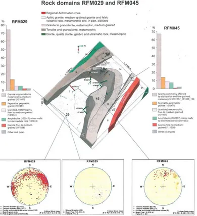
Fracture domain model
A special type of structure model has been constructed, a fracture domain model (section 2.7.3), and the aim of this model is to give input data to stochastic modelling of fractures and minor brittle deformation zones (DFN models). Fracture domains (FFM) are only identified for rock domains in the central part the local model volume. The fracture domains describe brittle structures, fractures and minor brittle deformation zones, in the parts of rock domains that are not occupied by regional and local deformation zones. The enhanced density of sub-horizontal to gently inclined fractures in shallow parts of rock domains RFM29 and RFM45 (Fig. 2-9) is also considered in the subdivision of the rock into fracture domains. This implies that the potential repository volume is located in two fracture domains and that these domains do not extend to the ground surface.
Economic geology – mineral resources
The region where the Forsmark candidate area is located, is, from the point of view of economic geology (section 2.8), regarded as a part of an ore province, as the bedrock is partly composed of supra-crustal rocks, meta-volcanites, which have potential to be mineralized. Minor mineralizations are known from the meta-volcanites southwest of the candidate area. In the sea northwest of the Forsmark candidate area there is a larger body of meta-volcanites. It has not yet been explored. A local gravity maximum corresponds to a magnetic low at the north-western tip of the Forsmark lens (just outside the mapped area, 3 km northwest of the candidate area) may indicate a mineralization. The metamorphic plutonic rocks occupying the central part of the candidate area appears to be non-mineralized. The largest ore bodies in the region are located in Dannemora, mainly iron ore, approx. 28 km southwest of Forsmark.
2.2. Review, geological evolution
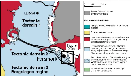
The report on the geological evolution (SKB R-08-19 Chapter 2) presents a verbal overview of the regional structural context for the Forsmark and Laxemar areas. Large parts of the text constitute summaries of results obtained by SKB during the investigations of the Forsmark and Laxemar areas (e.g. dating of rocks and fracture minerals). The Forsmark area is located in a tectonic domain formed during the Swecokarelian orogeny (Fig. 2-1; Tectonic domain 2), which is characterized by ductile, high strain belts striking WNW and anastomosing around tectonic lenses with lower strain (one containing the Forsmark area) . The structures displayed to be located at the eastern and western “ends” of Tectonic domain 2 (Fig. 2-1) are younger. Tectonic domain 2 is actually located along a regional structure that intersects, possibly transect, the Fennoscandian Shield, i.e. the regional WNW to NW trending structures in Forsmark form a part of a large scale structure that have a length exceeding 600 km (Figs. 2-2 and 2-3).
Regional comparison
A difference between the described early deformation (during the Precambrian, ≥ 540 Ma ago) in Forsmark and south-western Finland is that well defined
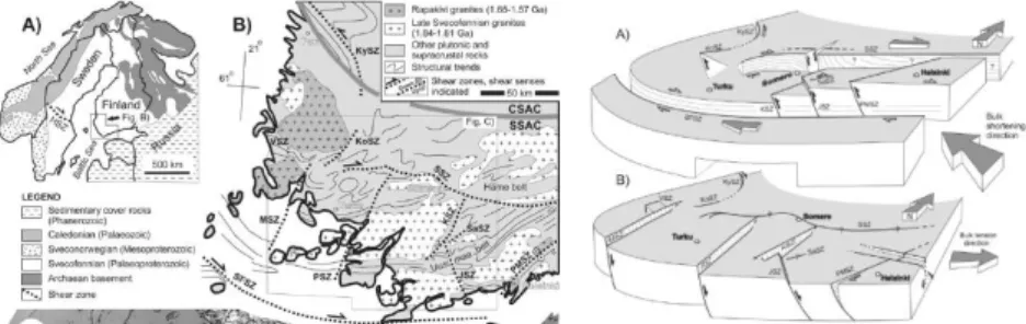
Figure 2-1: Regional geological setting of the Forsmark (modified from SKB R-08-19 Fig. 2-3).
Figure 2-2: Bedrock map of south-central Sweden and Southern Finland, modified from Koistinen et al. (2001). Stars denote locations of 1.87–1.84 Ga U–Pb ages of plutonic rocks, from Nironen (2003), Hermansson et al. (2006), Bergman and Söderman (2005), Bergman et al. (2005) and the Geological Survey of Sweden age database. Localities referred to in the text: H: Hyvinkää, L: Los, M: Masku, N: Naggen, Or: Orijärvi, On: Onkimaa, P: Pöytyä, S: Soukkio, T: Torsholma, V: Veikkola (from Bergman et al.
Figure 2-3: Schematic block diagram model for the evolution of the shear zones in SW Finland. To the left; A. An overview of the geological units in the Fennoscandian Shield. HSZ – Hassela Shear Zone (Fig 2-2). B. Shear zones described in the block diagram to the right.
To the right; A. The contractional stage at ~1.83–1.79 Ga. SE–NW contraction leads to a transpressional regime along the E–W trending Southern Svecofennian Arc Complex. Tectonic strain was partitioned into the major strike-slip shear zones at the margins and into steep reverse dip-slip shear zones between the strike-slip zones. B. The extensional stages at ~1.79– 1.77 Ga, 1.64–1.55 Ga and/or 1.26 Ga. The MSZ, VSZ and PSZ were formed and the other SZs were reactivated. Lines on the shear planes illustrate mylonitic lineations. The block south to the SFSZ is omitted for clarity. (From Vaisänen and Skyttä 2007).
a. b. c.
Figure 2-4: Characteristics of areas affected by high ductile strain, location of NW to WNW
trending regional zones (a.SKB R-08-19 Fig. 2-3), displacement along regional WNW to NW trending regional deformation zones (R-08-19 Fig. 2-22) and the magnetic signature related to deformation in the bedrock (TR-08-05, part of Fig. 5-1).
deformation stages controlled by extension tectonics are indicated in Finland but not in Forsmark (Fig. 2-3). In the Forsmark area the described periods of tectonic deformation are characterized by bulk crustal shortening (i.e., compression cf. SKB R-07-45 Figs. 5-3 to 5-5). Another difference is that the NE to ENE trending deformation zones in Forsmark are smaller. Still, the length of NE and ENE structures appear in both Forsmark and SW Finland to be restricted by WNW to EW trending zones, i.e. zones conform to the southern boundary of Tectonic domain 2. However, indications of extension tectonics in the Forsmark area have been found in a paleostress field reconstruction study (Saintot 2011) and are not included in the structure evolution model. What is emphasised here is that the description of the geological evolution should include relevant areas such as south-western Finland.
Ductile deformation at Forsmark
“Tectonic lenses, in which the bedrock is less affected by ductile deformation, are enclosed in between ductile high strain belts. The candidate area is located in the north-westernmost part of one of these tectonic lenses. This lens extends from northwest of the Forsmark nuclear power plant south-eastwards to the area around Öregrund” (TR-11-01 P17; cf. Fig. 2.4). Within a structure domain like Tectonic domain 2, lenses may occur on different scales and there is a possibility that the Forsmark lens closes south of the south-eastern tip of the candidate area (cf. Fig. 2-4a and c). Such smaller scale lenses will have higher symmetry than the larger scale Forsmark lens. Ductile deformation is found along both the northwestern and south-eastern borders of the candidate area (R-07-45 Appendix A13- P10, 14, 15 and 21). However, ductile shear are sparsely found in boreholes inside the lens and such zones are generally thin.
Plastic deformation such as folding and refolding is typical for the Tectonic domain 2 and the Forsmark lens contain in its central part a deformed “closed” fold (a sheath fold/tube fold – the fold display a closed structure on the geological map).
Ductile-brittle deformation at Forsmark
Major regional structures in the Forsmark area are the WNW to NW trending ductile to shear zones, e.g. the Singö, Eckarfjärden and Forsmark deformation zones (Fig. 2-4a) are mostly well described (the Eckarfjärden deformation zone is not investigated by any cored borehole) and located inside the areas with higher ductile strain. It is indicated that the zones are indicated to be curved, listric, as the paleoground surface is tilted (Fig. 2-4b). This character of the shear zones gives that reactivations associated with oblique displacement along the fault will cause tilting of the ground surface. The ground surface approximately coincides with an early formed denudation surface, the even and flat sub-Cambrian peneplain formed more than 540 Ma ago, and thus the period during which the distortion may have taken place is extensive.
Brittle deformation at Forsmark
It is indicated that “faulting with a conspicuous dip-slip sense of movement also occurred after 1.67 Ga ago along the steeply dipping ENE and NNE fracture zones inside the target volume” (R-08-19 P64), i.e. inside the north-western wedge of the Forsmark lens. Such block displacement must also encounter, be related to, dip-slip or oblique slip along other zones, e.g. the WNW to NW trending zones.
Study of fracture mineral indicates that a brittle regime prevailed in the bedrock at medium to lower temperatures, i.e. below ~400°C. The first generation of fracture minerals is given a relatively wide time period spanning from 1.8 to 1.1 Ga ago (R-08-12 P103), which is even from a geological viewpoint a large period.
Late deformation in the region around Forsmark
Comparing the regional interpretation of airborne magnetic measurements and the topographical map (Fig. 2-5) for the Uppsala County it is obvious that the main topographical breaks and low-magnetic anomalies coincide and represent deformation zones, faults. Notable is the systematic tilting of blocks displayed on the topographical map and the geometry of the blocks. What is special for the
characterization/ identification of structures in the Forsmark area is that both the magnetic measurements and the topographical data indicate that structures trending approximately NS approach the Forsmark area from the south. Some of the northerly trending faults may transect the Forsmark lens, at least along
Kallrigafjärden located southeast of the candidate area (cf. Fig. 2-4c). The Forsmark lens is possibly also cut by the structures that align the western boundary of the Gräsö block (the largest topographical break, > 30 m vertical displacement of the mean ground surface, within a radius of 10 km from the Forsmark site). The trough along the western side of Gräsö is locally deeper than – 40 m a.s.l.
However, it is pointed out that “On the basis of geomorphological data, dip-slip disturbance and eastward or northward tilting of the sub-Cambrian unconformity are apparent along faults that strike NNE-SSW, NNW-SSE or WNW-ESE in northern Uppland, where Forsmark is located. In particular, dip-slip displacement of the sub- Cambrian unconformity along the Forsmark deformation zone, with uplift and northward tilting of the bedrock block to the north of this zone, has been inferred. The consistent sense of kinematics and sense of block tilt inferred from both the 40Ar/39Ar biotite and the geomorphological data across the Forsmark zone suggest that at least some dip-slip displacement along this zone occurred after the
establishment of the sub-Cambrian unconformity during the latest part of the Proterozoic and/or the Phanerozoic” (R-08-19 P64).
To get a better understanding of different generations of regional deformation zones in northern Uppland and adjacent sea areas a block model comparable with that presented for south-western Finland should be produced (cf. Fig. 2-3). Of special interest is to consider faults related to late block faulting as such fault are most probably the structures that control the present circulation of the groundwater in the bedrock and having the greatest potential to reactivate. Before this is done it is difficult to answer whether or not the regional Forsmark area has an appropriate size to reveal structures that may contribute to the characterization of the Forsmark site.
Figure 2-5: Interpretation of structures in the bedrock based on air-borne magnetic
measurements (a;SKB R-98-32 Fig. 13) and the topographical elevation model (b.SKB R-98-32 Fig. 12), county of Uppsala.
It is not found in the site reports descriptions of how events or processes that have taken place in the regional surroundings of the site have affected the character of the Forsmark area, for example:
1. The intrusion of rapakivi granites, e.g. in Åland, about 1.5-1.6 Ga ago. Thus the distance from the centre of the Åland intrusion is in the order of two times the diameter of the intrusion (diameter c. 45-50 km and distance of about 75 km from the rim of the intrusion)
2. The Siljan impact, c. 377 Ma ago (Raimold et al. 2004), diameter c. 65 to75 km and at a distance of c. 170 km from Forsmark – the impact is located across the western part of Tectonic domain 2. Can be compared to a major earthquake in the vicinity of the site.
3. Late large scale block faulting of Tertiary age (Flodén 1980; <65 Ma ago) in the western part of the ENE-WSW trending basement culmination across Åland representing a late Cretaceous high (Lidmar-Bergström 1996) – the formation of the Åland deep between Åland and Uppland, c. -90 to - 280 m a.s.l. deep, by descending and tilting of large scale blocks with the sub-Cambrian peneplain preserved as top surface (cf. Söderberg 1993).
However, the two fundamental types of geological process that have impact on the late geological evolution (Tertiary to present, last 65 Ma) are:
The active continental margins and related regional stress field within the continental plates.
Compensation for the removal of the Palaeozoic sedimentary cover and loading and unloading cycles in connection to glaciations.
The study of fracture minerals gives indications of reactivation of shallow gently inclined fractures during the Quaternary. Fractures have been opened and presumably connected. However, there is no information about displacement. The search for Post Glacial Faults (PGF) in the Forsmark area and northern Uppland has not found any indications of late faulting or large late earthquakes (Lagerbäck and Sund 2008), i.e. displacement in Quaternary sediments indicating post glacial faulting. One of the most pronounced faults in the vicinity of the Forsmark area, the Forsmark deformation zone, has been investigated by a cored borehole (R-08-64). Even though this fault has a well-marked topographical expression northwest of the Forsmark village no indication of displacement of Quaternary triggered by moderately strong earthquakes was found at Kallrigafjärden, southeast of the candidate area (P-04-123).
The Swedish National Seismic Net (www.snsn.geofys.uu) has now been in operation for ten years and has so far only recorded minor earthquakes. Such earthquakes are enhanced, e.g. in the sea area northwest of Forsmark in Gävlebukten. There are indications of repeated seismic activity along zones. There is also a record of somewhat older earthquake data (Helsinki Catalog of earthquakes in Northern Europe since 1375) containing minor seismic events along WNW structures in the vicinity of Forsmark.
Comments on the description of the geological evolution
The description of the geological evolution of the Forsmark site is deficient in the description from the Palaeozoic to present day. However, the geological processes during this period left weaker indication as events presumably were of much smaller magnitude in a cold cratonic environment compared to the Precambrian period.
However, there are notable processes that are recordable and one of them is displayed by the distortion of the sub-Cambrian peneplain.
Information on late deformation are compiled elsewhere (e.g. distortion of sedimentary rock sequences in the Baltic Sea, denudation/weathering and uplift) and are more used to describe different geological periods (succession in sedimentary sequences) than presenting maps showing how structures are related and distributed.
Maps or block models are needed to describe different generation of deformation in the regional area surrounding the Forsmark site. One good example of thematic presentation of structure data is the report on “early Holocene faulting and paleoseimicity in northern Sweden” Lagerbäck and Sundh, 2008) with a generous presentation of figures and maps. These maps are of high value for the safety assessment as they indicate possible geometries of faults and faulting, i.e. how irregular active fault can be when formed by a combination of partial reactivation of faults and linkage of existing faults and what to measure as trace length of faults.
2.3. Overview, performed investigations
The documentation of the bedrock in the candidate area is based on: 1. Remote studies, 2. Field studies and measurements and 3. Surface based borehole investigations. The remote studies (1) comprise mainly structural analysis of helicopter-borne geophysical measurements and topographical data (elevation data, aerial photos). Field studies (2) involve geological mapping and geophysical surveys (detailed ground geophysical measurements performed at a late stage of the site characterization to compliment the helicopter borne geophysics, and gravity measurements, reflection and refraction seismic surveys). Detailed fracture mapping was conducted on cleaned rock surfaces at drill sites and along trenches. Surface-based borehole investigations (3) cover core logging, borehole geophysics, including TV-log/BIPS, borehole radar and vertical seismic profiling/VSP/.
The nature is regarded to have a high value in the Forsmark area and there are restrictions in possible drill site locations. Therefore, several boreholes, generally divergent, were drilled from some of the available drill sites. A total of 23 cored boreholes were drilled inside the candidate area and 21 of these are located in the target area. Percussion drill holes (38) were drilled either to support the cored boreholes or to investigate specific targets, e.g. structures related to lineaments.
The surroundings of the candidate area were more extensively investigated in order to establish the regional setting of the candidate area (documentation of the character of the regional area) and investigated by helicopter-borne geophysical measurements. Two cored boreholes were drilled to investigate regional deformation zones outsides the candidate area; the Singö deformation zone to the northeast (close) and the Forsmark deformation zone (at a distance) to the southwest of the candidate area. However, in the regional Eckarfjälden deformation zone, constituting the western border zone of the candidate area and located between the Forsmark deformation zone and the Forsmark candidate area, only two percussion boreholes were drilled.
The local model area covers the north-western part of the candidate area and the NW- to WNW-trending regional Eckarfjärden and Singö deformation zones
constitute the eastern and western boundaries, respectively. It does not include the south-eastern part of the so called target area. There are 20 cored boreholes in the local model volume.
Comments on performed investigations
It is obvious how the high-resolution ground magnetic measurements (11 km2, performed 2006-2007 /R-07-62/, appeared late in the site investigation) have contributed to the mapping of deformation zones (cf. SKB R-08-64 Appendix Table A-1). However, it is not clear if the high-resolution ground magnetic measurements have been used to update the distribution of rock types and rock alteration in the central parts of the local model area (rock domains RFM29 and 45).
Have structural relations in outcrops mimicking the relation between local scale structures (≥ 1 km) and larger scale (≥3 km) been noted and addressed in the three-dimension modelling performance?
The acquired data are extensive and the reporting of the site investigations is voluminous. The investigation techniques applied are of high quality. However, to evaluate the accuracy of the preformed interpretation of data made by SKB and the usage of all data recorder tests (for example alternative modelling) must be performed and further more detailed reviews should be done. Uniformity in data distribution is treated below. However, it can be noted here that the regional northwest-trending Eckarfjärden deformation zone, outlining the southwestern tectonic boundary of the Forsmark site is not investigated by any cored borehole.
2.4. Overview, scales of geological models
“The candidate area for site investigations at Forsmark is situated within the north-westernmost part of a tectonic lens (cf. Figs.2-4a and 2-4c). This lens extends along the Uppland coast from northwest of the nuclear power plant south-eastwards to Öregrund and it is approximately 25 km long. The candidate area is approximately 6 km long and the north-western part of the candidate area has been selected as the target area for continued site investigations during the complete site investigation phase” (SKB R-05-18 P5).
To describe the character of the Forsmark area/site several scales are used: 1. Regional model volume (SKB R-06-38 P23-14: 165 km2 large,
depth -2 200 m a.s.l)
2. Local model volume (SKB R-06-38 P24-25: 16 km2 large, depth -1 100 m a.s.l.).
3. A central area containing the proposed location of the repository (the near-field, target volume) containing mainly granitic and to
granodioritic rocks (rock domains RFM29 and RFM45, see text below; SKBTR-08-05 and SKB R-08-113).
The geological models are deterministic models. The types of models are:
A. Bedrock models – rock domains (generalized lithological model, cf. Fig. 2-9 the local model) – same resolution in regional and local model volumes.
B. Models of deformation zones – different resolution in regional and local models (Figs. 2-12 and 2-13, the local model)
C. Fracture domain model (only as a local volume model, Fig. 2-14) – used as input data to stochastic modelling of fractures, DFN, located outside modelled regional and local brittle deformation zones in the central part of the local model volume, cf. SKB R-07-45 and SKB R-07-46). The fracture domain model covers the near-field of the planned repository.
The models of deformation zones are three:
1. Regional model; surface trace length of deformation zones ≥ 3km. 2. Local model; surface trace length of deformation zones ≥ 1km. 3. Modelled minor deformation zones, MDZ, in the local area; surface
trace length of deformation zones ≤ 1 km. Used together with the local model in the layout of the repository.
A detailed description of the bedrock geological map at the ground surface describing distribution of different lithologies (rock types) and gently inclined brittle deformation zones and steeply dipping regional brittle deformation zones (>3 km trace at the surface) is given (SKB R-08-128).
“Local models for the geometry of rock domains and deterministic deformation zones, with a higher resolution, are presented for the first time” in a report from 2006 (SKB R-06-38 P5). These models were further developed in 2007 (SKB R-07-45 P5 and Appendix 15) and added was also a description of minor deformation zones (SKB R-07-45 Appendix 16). A synthesis of the characters of different sets of brittle deformation zones was presented in 2008 (SKB TR-08-05 P144-153) and described are:
Sets of brittle deformation zones.
Orientation of fracture sets within the different sets of brittle deformation zones.
Fracture minerals in different sets of brittle deformation zones.
The site description at completion of the site investigation phase is focused on the local scale description and also considers the minor deformation zones (MDZ) at repository depth (SKB TR-08 AP.4).
Comments on applied scales
The different scales of describing the character of the bedrock at Forsmark are mainly found appropriate. The exception is the description of structural relationships, including internal pattern, of structures belonging to different sets. There are detailed fracture maps presented for cleaned outcrops (cf. SKB R-05-18 Fig. 5-31), but the structure interpretation of the fracture data is missing. Sketches displaying character of zones are missing.
The dispersion of boreholes in the area at repository depth do not allow modelling of geometries of subordinate rock types within rock domains RFM29 and RFM45, i.e. in the near-field of the repository. However, detailed mapping and modelling of rock types and tectonic structures will be performed during the construction of the repository (SKB R-11-14). The outcome of a late borehole in the northern part of the Forsmark site (SKB R 08-64 Fig. 4-8) display that there is a greater spread in the orientation of deformation zones than postulated and that there are also indicated intercepts of possible zones that are not included in the model (see text below,
section 3.7). It is a plausible assumption that the density of deformation zones can be estimated but their locations can be uncertain.
2.5. Overview, base data – uniformity in data
distribution
Exposed rock – outcrops
The percentage of water-covered areas inside the local model area (Fig. 2-6a) is not found in the reports by SKB. The proportion of wetland is relatively high (25 to 35 % in some catchments). The degree of exposed rock in the land area of the local model area is low (5%, while 13% in the regional model area; SKB R-05-18 P100) and outcrops are unevenly distributed (Fig. 2-6b), e.g. there are few outcrops in the central part of the local model area NW of lake Bolundsfjärden. For example, at drill site 1 (Fig. 2-6d) the depth to bedrock is generally between 4 to 8 m. The maximum measured depth to the bedrock in the Forsmark area is 17 m. Despite the variation in depth to the bedrock head, the upper surface of the overburden, is “quite flat” (SKB R-06-18 P101). In other words, the degree of exposed rock is more enhanced outside the central parts of the local model area than in its central parts, i.e. outside the area of the potential repository.
Elevation data
Topographical information used is elevation data:
Land areas inside the local model volume and main parts of regional model volume (SKB P-02-02) grid 10 m.
Regional land areas outside the regional model volume (Lantmäteriet, GSD (Geografiska Sverigedata) - Terrain Elevation Databank, elevation data bank 50+) grid 50m.
Sea areas between Forsmark and Gräsö (SKB P-05-101), inside the local and regional model volume – measurements performed by SKB.
The resolution in the elevation data covering land area and sea area in the local and regional model volumes are not identical, but the difference may have minor
importance for the geological interpretation as SKB states that there is a low correlation between brittle deformation zones in the bedrock and the topography in the Forsmark area (R-06-38 P120).
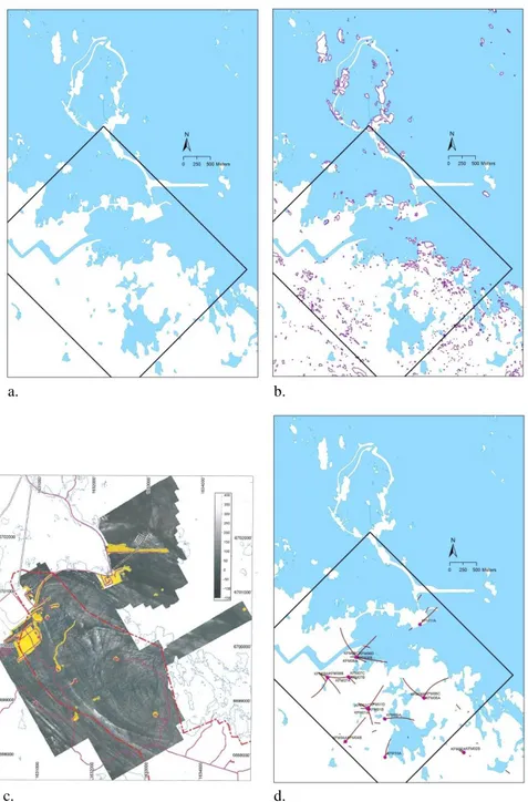
a. b.
c. d.
Figure 2-6: Data acquisition in the Forsmark area (the square represent the local model area):
a. Water covered areas (SKB GIS database) – direct observation of the bedrock not possible, b. distribution of outcrops (SKB GIS database), c. ground magnetic representation of the bedrock (42 % of measurements are made from boat; line separation 10 m and point separation 2-5 m (R-07-62 Fig. 3-7), and d. cored boreholes and their surface projections (SKB GIS database; two boreholes are not displaced: KFM03 and KFM12 located southeast and southwest of the map area. Short traces are percussion boreholes).
Ground geophysics and seismics
The most notable amongst the geophysics measurements (cf. SKB TR-08-05 Fig. 5-17 Coverage of airborne and ground geophysical measurements) are the high-resolution magnetic ground measurements (Fig. 2-6c) that well display the pattern of moderate to steeply dipping structures in the bedrock and the complimenting
reflection seismics (cf. SKB TR-08-5 Fig. 5-20) indicating moderately to gently dipping structures. However, the bedrock surface intersections of brittle deformation zones are generally covered by soil and only a few has been exposed in trenches. The outcome of performed refraction seismic surveys (profiles given in SKB TR-08-05 Fig. 5-22) is that “there is only a moderate correlation between low velocity anomalies and lineaments defined by magnetic minima or modelled deformation zones” (TR-08-05 P132).
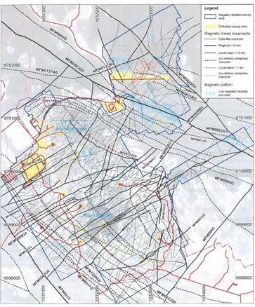
The structure interpretation of the detailed magnetic measurements (Fig. 2-7) forms base data for modelling of structures in three dimensions, evaluation of structure homogeneity and structural relations (pattern) within the area.
Figure 2-7: Low magnetic lineaments inferred from the integration of high-resolution ground
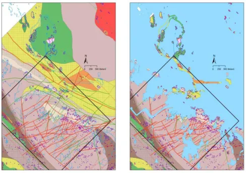
Figure 2-8: a. Geological map of the Forsmark area (SKB GIS data - displaying lithologies and
deformation zones /all zones – also zones with surface traces less than 1 km long/; cf. Bedrock geology modelling stage 2.3 (R-08-128) for legend, and b. same model as Fig. 28-a displayed with sea area and lakes masking the bedrock geology.
Subsurface data acquisition - Borehole investigations
The borehole programme (Fig. 2-6d) in the Forsmark area has to some extent been steered by restrictions (proclaimed by the county administration in Uppsala) because of natural value of the sites proposed for drilling (cf. section 2.3). 21 cored boreholes have been drilled from 8 drill sites inside the local model volume From additional four drill sites outside the local model volume 5 borehole have been drilled; four southeast of the local model volume and one southwest (targeting the regional Forsmark deformation zone). No cored boreholes investigate the Eckarfjärden deformation zone bordering the western side of the candidate area.
Uncertainties – data acquisition
The ground surface is generally the only surface where data could be sampled. The detailed magnetic measurements are of good quality and display bedrock features where the bedrock is covered by soil or water (fresh water and sea water). Outcrops are more common within the local model area along contacts of rock domains. In some cases brittle deformation zones indicated on maps are drawn across outcrops. However, descriptions of the characters of such zones are not found in reports.
One of the main uncertainties (1 out of 3) is the location of acquired data, especially the borehole data. Many of the cored boreholes deviate clockwise from the planned direction. This sort of divergence is commonly depending on the drilling performance. How much the divergence affects the planned outcome of the borehole investigation is not known to the reviewer.
The second main uncertainty in the geological description of the Forsmark site (as for most areas) is the step from two-dimensional (the geological and structure maps; cf. Figs. 7 and 8) to three-dimensional modelling (Figs. 9, 12, 13 and 2-14). Drilling boreholes in different directions from a drill site is an investigation technique not earlier applied, an investigation of volumes more than specific targets; a technique that favours cross-hole interpretations. However, the separations of the endpoints of boreholes are in most cases more than 500 m at repository depth.
There is not presented any analysis of locations of rock volumes within which sets of structures, especially those that that are extensive (e.g. ≥ 1 km), can occur without being intersected by a borehole – a combination of blind volumes and sampling bias. Each set of deformation zones will have their own blind volumes. For example, structures trending NE to ENE may, if they exist, cross the central part of the local model area without being intersected by a borehole. If existent, such zone(s) may affect the central parts of the planned repository.
The sea and lakes cover a large part of the local model area and also the central area below where the repository is planned to be located. This may not affect the characterization of the repository as much as the modelling of structures during the construction of the access ramp (Fig. 2-8).
The borehole configuration and the reflection seismics may catch the gently inclined to sub-horizontal local zones in the area. The third main uncertainty considers detection of minor or thin local sub-horizontal deformation zones at deeper levels. If they exist they may have effects on the layout of the repository and may cause problems during the construction of the underground facility, the repository.
2.6. Review, geological models – rock domains
The spatial distribution of rocks in the Forsmark area (Fig. 2-9) is displayed by using a rock domain model. The model displays also the ductile deformation as the geometry of rock domains is mainly a result of such deformation.
The concept of rock domains and rock units needs clarification. Rock types (petrographically determined) are mapped in outcrops and drill cores.. Within an area the bedrock is generally composed of some dominant rock types accompanied by sets of subdominant rock types (e.g. dykes or layers/bands). Furthermore, the bedrock may locally be affected by deformation and alteration processes. The modelling of the bedrock geology may need simplification depending on scale of modelling, how rock types are distributed, how superimposed deformation have distorted the character of the rock, and the relation between rock types.
To simplify the description of the distribution of different categories of rock types in the regional and local models a concept dividing the bedrock into rock domains (cf. SKB R-05-18; Table 5-20 and Appendix 1) has been applied. Rock domains (SKB R-03-07 P9) are defined as the “combination of the composition, grain size, homogeneity, and style and inferred degree of ductile deformation of various rock units” (unit, see below). A modified regional model and a local model are presented in the Forsmark modelling stage 2.1 (R-06-38 P113). In that model, rock domains RFM29 and RFM45 are inferred while other rock domains are the same as in the previous model.