SKI Report 95:70
Research
Crack Characterisation for In-service
Inspection Planning
Peter Ekström
Jan Wåle
November 1995
ISSN 1104–1374 ISRN SKI-R-95/70-SE S T A T E N S K Ä R N K R A F T I N S P E K T I O NSwedish Nuclear Power Inspectorate
POST/POSTAL ADDRESSSE-106 58 Stockholm BESÖK/OFFICEKlarabergsviadukten 90 TELEFON/TELEPHONE+46 (0)8 698 84 00 TELEFAX+46 (0)8 661 90 86
E-POST/E-MAILski@ski.se WEBBPLATS/WEB SITEwww.ski.se
In-service Inspection lanning
Jan Wale
November 1995
".= .... r' ... concerns a the ~W~Ofllsr
Power Inspectorate (SKI). The conclusions and viewpoints presented in report
Abstract
During in-service inspection by non destructive testing the reliability is highly dependent
on how the equipment is adjusted to the specific object and to the anticipated crack
fea-tures. The crack feature and morphology vary widely between different cracking mecha-nisms and between material types, in which the cracks appear. The major objective of this study was to characterise a number of morphology parameters for common crack mecha-nism/structure material combinations. Critical morphology parameters are crack orien-tation, shape, width, surface roughness and branching. The crack parameters were evaluated from failure analyses reported from the nuclear and non-nuclear industry. In addition, a literature review was carried out on crack parameter reports and on failure analysis reports, which were further evaluated.
The evaluated crack parameters were plotted and statistically processed in data groups with respect to crack mechanism and material type. The fatigue crack mechanisms were classified as mechanical, thermal or corrosion fatigue and the stress corrosion crack mechanisms as intergranular, transgranular or interdendritic stress corrosion cracking. Furthermore, some common weld defects were characterised for comparison. The materials were divided into three broad groups, namely, ferritic low alloy steels, stainless steels and nickel base alloys.
The results indicate significant differences between crack parameters when comparing data from different crack mechanism/material type combinations. Typical parameter values and scatter were derived for several crack mechanism/material data groups, where the amount of compiled data was sufficient for statistical significance.
Sammanfattning
Yid ofOrstorande provning ar provningens tillfOrlitlighet beroende av hur provnings-systemet anpassas tin det objekt som skall provas och till de fOrvantade defektemas morfologiska egenskaper. Dessa egenskaper varierar avsevart mellan olika sprick-mekanismer och meHan de materialtyper dar sprickoma upptrader. MaIet med denna smdie har varit at[ kartlagga et! antal parametrar som beskriver de morfologiska egen-skapema hos de vanHgaste sprickmekanisrnfmaterialkombinationema. Kritiska parametrar ar sprickorientering, form, bredd, ytfinhet och fOrgreningsgrad. Dessa parametrar har hamtats direkt fran skaderapporter eller uppmatts fran foton over trvarsnitt pa sprickor
som redo visas i rapportema. U tvarderade sprickor ar skador som intraffat inom
karn-teknisk och inom konventionell industri. Dessutom har en Htteratursmdie genomforts med syfte art sammansililla data fran liknande parametersmmer och darutOver samla in resultat fran skadeutredningar fOr egen utvardering.
De uppmatta parametrama har behandlats statistiskt och grafiskt i grupper indelade efter
sprickffiekanism och materialtyp. For utmattnmgssprickor sarskiljs mekanisk, termisk och korrosionsutmattning. For spanningskorrosionssprickor sarskiljs interkristallin, transkristalli:n och interdendritisk spanningskorrosion. Dessutom har nagra av de
van-ligaste svetsfelen utvarderats fOr jamfOrelse med sprickoma. Materialen har delats in i tre
stora grupper, namligen ferritiska laglegerade staI, rostfria sill och nickelbaslegeringar.
Resultaten indikerar art signifIkanta skillnader fOr utvarderade sprickparametrar fOreligger nar olika sprickmekanism/materialgrupp-kombinationer jamfOrs. Typiska varden och spridning fOr de utvarderade parametrama har bestamts fOr alIa de datagrupper dar ett tillrackligt undedag fOrelegat.
of contents
Abstract. ... 2 Sammanfattning ... , . " ... 3 Table of contents ... 4 1 Introduction ... 7 2 Objective ... 83 Crack evaluation methods ... H • • • • • • • • • • • • • • • • • • • 0 0 • • • • • • • • • • • • • • • • • • • • • • • • • • • • • • • • • • • • • • 8 3.1 Recorded morphology parameters ... 8
3.1.1 General data ... 9
3.2.1 Crack morphology data ... 9
3.2.3 Limitations ... 14
4 Results ... 15
4.1 Survey of compiled data from evaluated cracks ... 15
4.2 General description of crack morphology ... 16
4.2.1 Mechanical fatigue ... 16
4.2.2 Thermal fatigue ... 17
4.2.3 Corrosion fatigue ... 18
4.2.4 Intergranular stress corrosion cracking, IGSCC ... 18
4.2.5 Transgranular stress corrosion cracking, TGSCC ... 19
4.2.6 Inter dendritic stress corrosion cracking, IDSCC ... 20
4.2.7 Weld flaws ... 20
4.3 Orientation in surface and through thickness direction ... 22
4.3.1 Mechanical fatigue ... 22
4.3.1.1 Ferritic low alloy steeL ... 22
4.3.1.2 Stainless steel ... 22
4.3.2 Thermal fatigue ... 23
4.3.2.1 Ferritic low alloy steel ... 23
4.3.2.2 Austenitic stainless steel ... 23
4.3.3 Corrosion fatigue ... 23
4.3.3.1 Ferritic low aHoy steeL ... 23
4.3.3.2 Austenitic stainless steel ... 23
4.3.4 IGSCC ... 24
4.3.4.1 Ferritic low alloy steel ... 24
4.3.4.2 Stainless steel ... 24
4.3.4.3 Nickel base alloys ... 24
4.3.5 TGSCC ... 25
4.3.5.1 Ferritic low alloy steel ... 25
4.3.5.2 Austenitic stainless steel.. ... 25
4.3.5.3 Nickel base alloys ... 25
4.3.6 IDSCC ... 25
4.3.6.1 Nickel base alloys ... 25
4.3.7 Weld flaws ... 26
4.3.8 Uteraturedata ... 26
4.4 Crack shape and branching ... '" ... 27
4.4.1 Mechanicalfatigue ... 27
4.4.1.1 Ferritic low alloy steel ... 27
4.4.1.2 Austenitic stainless steel ... 27
4.4.2 Thermal fatigue ... 27
4.4.2.1 Ferritic low alloy steel ... 27
4.4.2.2 Austenitic stainless steel ... 28
4.4.3 Corrosion fatigue ... " ... " ... 28
4.4.3.1 Ferritic low alloy steeL ... 28
4.4.3.2 Austenitic stainless steel ... 28
... 34 ... 35 u..:.; ... "., ... . alloys ... . u . " .... , ... ,. or .. " Il' ... -'" . . . . " ~ .. '" . . . ~ " .. III " ., .. ,. ... ~ ~ .. " .. "' .. " ,. ,~ . . . ~ . . . " .. ~ .. " " . . . .. 1 Nickel alloys ... . 4.5.7 'Veld flaws ... . Concluding ... . width ... 37 1 Mechanical fatigue ... .. 1.1 low alloy ... 31 ... ,. ... 39 4.6.2 '-',JI"-'"'-' . . . 52 low alloy ... . Aul~telllitic stainless ... .. alloys ... .. alloys ... " ... 56 ... , ... , ... 58
5 6
"' ... "' ... rougmlteSS ...•... 80
1
The "''''IJ'''J'''''''~
as the nature structure under eXilWU.ml.!;lOIl
mance
the subsequent ... ,"""""'v .... and qualification stage.
~"DT equipment and procedure compo··
nent to type
straightforward
is known, optimisation with respect to defects can he problematic.
The main reason for this is that data not always are available as to which crack chara!:reristics depend on underlying degradation mecha.nisrns.
extreme """'., .. " orientation,
to ri"",","'n-n
surface roughness.
as as more
project are presented this report, which been the form of a Ilel()pmlent and
quali-data handbook can be used by NDT enE:RI-e~erS working with
is a """,,-,,,... ... n
want to em.ol:llilSHie not to atexmO'OK.
is ana
are rl{.~,eal:;a
wa.r.; to most common
scatter were deternrunt;;{1,
... ", ... ".. from a large u .... , ... V' ... FUfitller:moc-e, a conrpre:beIllsi for 1 0-15 years. ~,",",,",,""'AL a ... "' ... u .. , .... dlesCfl[l!tlOU. l1ffilH,aUOllS of
...,u.,'I-' ... was designed
... 'lJu.u as 1-'''''''''' .... '''.'''.
limited number of eX1JreSS11JllS
of n~I''l'!n,p.tp.r~
~Ol[fipleIl[leIU to the recorded
reports for this pru"OOlie
n-'.::I'U~.:l.U'LJU3 over
recordmg of the
morpho-and crack ... n ... h
mate-nmrlel)ers a
""'U'll-'U·'Y both the of
can
alternating thermal etc.
or cOlmnOn!~nt
on
thickness was also rec:orclea.
to a
centre
some eXl'Jre,SSlIJflS are
was
etc.
etc.
cold worke,d.
crack
is is to a
to is L
are
are
sha~ in surface same are as
Number damaged area.
was was was
Crack
Crack
Crec
direction
1, ru-e to a
stone is
amount
was measur~,a as a mean
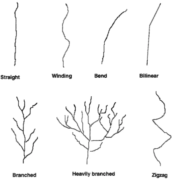
Straight Winding Bend BiUnear
Branched Heavily branched
Zigzag
Fig. 2, Scbematic illustration of different types of crack sbapes.
measure. mea..;;urements are an accurate a mea-surements. SnlJill..G uate anmrnel~lC,u mean
of
ugtme1SS on a macro scale not
ona
was,
measurement length is range
length range of 1-2 mm.
:---mm. see
measurements. anl;;:.mipm. see
I
Where:
was recorcled at Su.rface, at hrut' can a mme bY=~'~L"'§ t\vo um~m~ss,not
to 11 to aradius: was it wa. ..
IH"""""..!.U;;'-to represent
a amount
3.2.3 Limitations
with such
investiga-" ... 'investiga-" u .... investiga-"investiga-" ... 'u ... ~.u. for each case. A importance.
information
none one
means
most registered cra,:;kS. The lack data shown in the presentation
results in 4.
A crack a three-dimensional UI.'.Ii.,;..;. ... ~. this do not cover
a ofa course
of mtc)rmaU()fl
over must H""" .. ""-Ih", .. ,,,
example, crack width at the surface is to be varying along crack length
on surface. The crack width measurements are made on micro graphs showing the
through direction. These photos are from a cross of
are
aelJen,aeEU on were
both
two UULl'i\U. .... me~CnaniSmS.
"'" .... "'''''' .... z;; was CH1SSlIlea groups fatigue 0/6 s 1 1120 two or more 1112 1/6 39/4 7 1 :I 1
Ferritic low aUov Nickel base anows
Low high temperature Ferriticlaustenitic .:nruJlu ... ».:'!I Alloy 182 steels
Alloy 82
4.2 General description of crack morphology
evaluation. Hv'''' ... ·n!
UltV .. U<lI,UJ.i)JlU is
If''-P'Cl'''' derived
typical crack leaturt~S are shown by micro graphs in
Appendix
4.2.1 Meclumical fatigue
by
"-"" .. ,. .... .,., .. stresses or .11.'"'''', ...
and corrosion surrounding emn.rc.nm.ent are considered insignificant
or red!isuibl!ti
see
the stress mtf:ns:i:tv factor
stress diI'eC1tlOJrl. an onentaticlD to con-is perpendicular to growth for fatigue
soot"ace rou~h11!ess mc]us,es with an increa~iin~ stress intt~nsttv
same as
deviates
ber addition, the
... 1[4 .... 8'"- c:racmig com.ull1red to me~h~Wcal .lQ,iJ~Jr.I,"'''',
thermal occur a
is IJi:I.'l,ll,;J:llll
some ~.oocts
pattern on the sur-or
see no 8 - 9
or tnermial
most cnlUill;;WJristlc features of C01:ros~lOn
Int,er~U"rulwa~ stress cmros;lOn ... g,.., ... , . . ,I;, A ... ' ... , combined en~~cts
stresses and COl!1'O;~101n. stresses.
of aus,ten.1t!c stainless steels.
stresses are ",,,,,,,'1" .. '\(11""" CrillCK:Ulg to occur. KeSU1Uw. stresses
important
causes faijltm~s
case to cracks. scale. are parameters as thickness UU'\.i~i.lVU morphology to
2.
more more common not it or in a coarse base notof
mate~ .not4.2.6
crficking, IDSCC occursstructure.
are
logy some cases it
The reason structure nf'T\lTPf'.n
a difference 10Iligit1udinal dirloction cornDa:.red to transverse omectlOl1
in the transverse dendritic
same diIlection as the tle1J!dntes. an 1..U1oC11"""·'-'-~,Ul!;\"~ sm()om T:ypical examples
a'l"~'''''I'>''' no -41 Aor~endix2
Weld are included in the study comparison with service induced
to
joint surfaces.
Hot cmClaIlg
are fusion
,""u"',,,,"',"'''' induced cold cracks the heat affected zone next
are to
fusion between weld pMses also occur. Typically. they are
ex-and
nOl1-$t:ralJ~!lt. The most common
tation ·c:faiClO.!lg parallel to the direction, and
occur
cracks are located in the
centre. However, to
4.3
Thenun:mer
in surface
through thickness
1.
suo:ac.e orientation is relllu:eu to welds or ge()mt~tnc:u ,U.,"'\'I.U""·~,
on the
are one or
trolled geometrical features.
",n"~'O;t"p, on~:;:ntilti(Jln is
con-in the through tb14::kIJ:eSS di~ion are for only exc:eotlon
crack tends to follow the geometry a angle. No informatiQn were available on
were seven.
n . . .""""" are
cmmel;::tU:fn to tm~::K.ll,ess an~~les are 65'>
craCKS from the non-nuclear maustJt'V only one
Cr'dlCg are lm1:mk~
are is to steel were are at are no
due to the However. of the stone
pattern on seems to
pipes.
4.3.3 Corrosion f~tigue
4.3.3.1 Fenitie low alloy stsel
r<:i'l:I:,rolr~ were the nm'HliuclJ~r industry. The nmnrn~r
Ten are ,L'V'\<'U,,",U at were On~;!nUX1
parallel to the weld. Out the six cracks running parallel to the weld,
three are l00ttea coarse zone at a 0-1 mm
fusion the weld metal and one 5 mm away from the weld. The
OJien-but
O'ne
was
through tbtc~kness orientation but
are lOcate:o at
are are
across
were me:astlreil,
4.3.4.2 Stainless steel
Out evaluated cracks four were non-nuclear industry.
'Ha.!.U.l""!'!i'l> steel one each in terl'l11C ",~"uU''''''''' steel and preCIPItatIOn llaI'oo:nlD,g
cmme,cUcrn to
located worked austenitic snurue;ss pipes and six cra<:ks are from laIJ10nttoty
test spe:CH'llen.S.
.,,,1"l'!!'i .... '" orientation,
CnltCKS, even cracks which are
located is parallel to the The 'Orientati'On
m'Ore unclear due to lack of mtlilmultion.
4.3.4.3
600. Ten those are labom-is a
basft evaluated 0-is common four cases as laboratory tests. were
onentattcln in t h .. ", ... h thickness ri."'.,...~" • ..,. ...
two cases mont:. £Ui.VU;t1I;'U.UJA. is available on
cracks were are
mens. tnl'!OUlilm, ttucii;:ness angles are
a nmnug,'h .~u",..,.u .... '>" ,.., .. ""'~ .... """.
not meam.:ngtUl to
6
non-emfirc~rHr&enl:s at
growth
were seven
onem:amm was , ... h'~"""'!7",r1
are that of common
at cirl::amaferential
onl~nti!.t1cin C!\:!;pe:nas on
stresses and serls.Uisa:llou P"'~""''''.u t''"''''' ... ,''''
starts at surface then it turn~
cracking me;Chjlm~;mS
weld IGSCC was not
of
line.1
cracks occur seven .... "w, .... "',
... w"'~ from the nu~:::le(U' i!lldul~trv and
two are
area. In two cases more
iJ.I..a,UvJUJ.UlJ;:; was rec:or{ied
ten
of
nOl:1-nUClea1' industry were
through thil~kness The shape cracks. one available. to the surface dinectl!Cm one two the
nOlll-naC.l,eaI maustlrv there no infoD'lllation
partly
measureaas
111m.common
nents
stone p,uu~r:n.
'"'''''''VA''' stone pai:tern.
"",""",>"1.>-,,, bent or "'~"E>'U"~J
one pattern.
~vv'u_sronep~emA~'~'~
"' .... 'U,b"U "'.,a"' ... have, in mostca..qes, more five the damaged area.
rusltan,~e between cobble stone pattern was in cases
nnn.
4.4.3.1 Ferl'iticlow alloy steel
ten are ID
the through thickness direction. Four the cmcKS are more or branched. The number branches each are typically 1 - 3.
4.4.3.2 Austenitic stainlers steel
One nuclear industry was evaluated. The the through thickness no LAJU ... A . . " ' ... .,'vu .... 4.0"'".." ... on
4.4.4 IGSCC
more than ten cracks erist. Macroscopic branching was recorded five The number ofbmnches those cracks were measured. as 0.2 ~ 2.O/mm.
is
were recorded
011
cases, all
mlJo:l~il IGSCC-TOSCC
were three cases of pure Oral!lCnmg is not common for
evaluated crack
a
pre1Cipltail0n hardeIlmg stainless acm.ck
branching 10 brru:lCh1eSltnm.
evaJua:red.
!:':tt".'lIl:':n labor'dl:Orvcracks
and ..."" .... "roe. cracksThe 'Vat'llatllQIl show
mat
straight, or
one {OSee crack that .... JlLu.<un
Alloy 800 and the renuulilmg in 600. no du]:erence in shape between laboratory cm!cKS and
pure ... ""-... ll .... eJ[Cel,t b:mnctresJ'm.tJrl. The num.ber cracks the damaged a:re,a
are two cracked areas Qh.""'t'lf1'n
"' ... .." .. "''!-,''' •• " test and one <!;lPf"""1/'"'P. UIUU\A;;;U
alloy .l.uu ... u.,!';ID mente;(! in one is more two pnrvp" or WUIUIIlg one 15 cases more
from the nU!::;le;ar industry, and 11 are
was recorded one crack L-;
Fig.
steel.
4.4.7 'Veld flaws
cold cracks and lack fusion aeI€;::cts are controlled by the weld joint
geo-the cold cracks follow an mtt~r~I:amtlar crack path and show a ia~jgeG ... ,'"
shape. The of flaws are located fusion line, which produce straight
occur as
are "'V~j'''''''''''''. each case is
occur as
Concluding
Crack typ~ Material
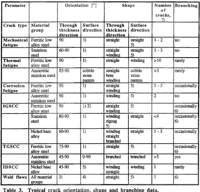
grOM}} Stainless steel Nickel base alloy TGSCC IDSCC 80-90 60-90 3) 2 1) <4 1) straight 1 - 3 1 >5 4)
Table 3, Typical crack orientation, shape and branching data.
1) Conirollied
"'V"""""."I or cold forming.
Lack of fusion flaws and cold cmcks are controlled by
4) Lack of fmdoo flaws and cold Cl."aCks are ... _____ to the weld
5) by
Commoo on a micro scale.
Number of macro c:racks ID ilie damaged anYd, dose to the evaluated. Clack.
no
occasionally
have a
tip are
a tip
cracks in austenitic SUiUUI;:;/SS
crack was .u","""''"' ... ,~
crack radii is shovm
a crack
radii ~ 5 other
are .---'-J transgranular. The crack
22 recorded crack
to crack occur
out 18 evaluated cracks.
One was
steel
""~ ... , ... , ... The crack tip
Crack
is
<1J.Un.
less 1
all cases
. . . 'AL . . . ,'''"' wt>oe:ars at the tip
stainless is S; 2 ten of tip 2 < 1 IlID, show radii 2 was two radius
one exc:C'PttOn. all
70 60 50 40 30 .Ill: 20 (]I III
...
<.> 10 0 Cl} Cl} Cl} (.) 'iJ) 9 'iJ) 'iJ) Cl}gs
z
E i
E (.) Cl)z «
0:,; 0:,;z
u
0:,; 0:,; u 0:,; ..c ..c E E {) u { ) <.:> (.) <.:> (.) (.) (.) li li5
'iJ) 'iJ) Cl) Cl) Cl} (J) (J) (!) (!) f3. ..c S2 S2 ~ ~ GrE
9 ::it ::it I - <.:> I-measurements
at sm·ni(~e niolli',fI versus
at point I.JJ.V!LLvy versus rus!taD.(;e
versus dls'!:am:;e from
connc~ted. to
me~cb:amcal A"""4 .... ~ • .., cracks in +''''' .. · ... ti,,.
t11:l.(;KDleSS and crack ,,~ ... ,'n,,,, ,
and 2- respectively.
J.I;';.:lUUIl are nTje;sente:d
midway are LI,nnu.;.u versus crack J"i"", .... n',' .. 'nl
m(},[[f:a versus distance from
l l u .... ...,.,""' .... 1lO crack
are
in
mm
1000 1 I) 0 1-··· .. ···0··· .... · .. ···•··· .. ··· .. · .... f;}··· .. ··· .. ····,.·· .. · ... ., o o .loi1 10 0 rI:
...
Cl (.) 0 1 0 20 40 60 80 100 versus ",r"",'OT 1000 Cl 100 n .n. 0 0 0 Cl Cl Cl Cl D o 2 8 10 [mm] atHlOO Non-nuclear Cl Surface cracks 0 0 100 Nuclear crack 0 Cl .3:\ iO (,) !!J
...
0 1o
20 40 60 80 100 [%] venus1
4.6.2
1000 Cl f Cl Cl D j~···a I Cl iJ Cl Cl I 0.1o
low aUoy U .... ,UU'iU fatigue and 7-50%, resoec Cl 5 10 alloy wereare more homogenous,
Cl .".' 15 range mm to the measured crack HI"""-",,,, are larger and more sca,ttel~ed. is too
for accurate ,...ro. ... r-,,. versus distance to
Cl o a o Cl 10 ~ ___ . ____________ .~ __ ",_. ______________________ J
o
20 40 60 80 100}l'ig. 12, CriiCk width at surface and midway for 5 thermal fatigue cracks
'Versus crack depth/wan thickness ratio.
1000 r---.---~ Cl 00 Cl Cl .l!!1 1 0 fr··· .. · ... · .. · .. ··· .. · .. · .... · .. ···· .... · .. · ... · .... · .. · .... · ... ·· ... --... --... --... --j t)
=
...
U Fig. 13, o 2 4 """', .. ,..." at from crack tip.130 g;:
...
"IC:$-
--
-i 40 -. .l!!: (,) I!J...
'" 0 20o
o
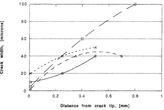
0.2 OA 0.6 0.8Fig. 14, Crack width at tbn:!e locations for each crack versus distance
mm
depth/wallthickness ratio 12·24%.
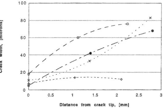
4.6.2.2 Austenitic stainless steel
The crack width was evaluated thermal fatigue cracks austenitic stainless steel.
The range mm,
5 - 40 mm and 3.25 - 100 %, respectively. results are shown in The
1000 100 ~ Hi u II:j
..
(.) 0IIII! Weld materia! o Base material w ~~~u .. ~"~" ... ~ .. ~_~~~~" .. ~~_~~~~.~"~~~,.~~~~~~.~~.~"~".~~.~~ •• ~ .•• ~ .. ~,.~~a~_.~." ••••• ~ •• w*~~~".".~.~ •••• ~g."~_~~¥~_'~~." •• _~ •• ~ ••• n~.~.'~~.~'~~~~~.' 0
og
0 0 0 IIII!DD IIII! 0 0 5 10 15 20Distance from crack
100 80 '0000 X oe . . o o o o o o ,
-..- -e--
, -~" , ~~ -/ " ,-
~ --/" ,~ ~'-'" 60 / ' # / ' ~ , A -=....
"
i 40 ..tI: / ' ... x / ; " -(.;I (IJ ./ . ' "'/~ ~ ~-
---
4)- --
- ---
----~----
- -0...
0 20o
o
0.5 1.5 2.5 3Fig. 11, Crack width at three locations for four thermal fatigue crack.s in mm.
4.6.3 Corrosion fatigue
4.6.3.1 Ferritie low aUoy steel
In 20 corrosion fatigue cracks :in ferritic low alloy steel were evaluated. The range
u,",~",.u. wall ratio was mm, 4
-1 - in
number of evaluated cracks is larger compared to the ",,..,.,'un,,, two fatigue mechanisms,
but scatter width data considerably The reason exc:eSS·lve
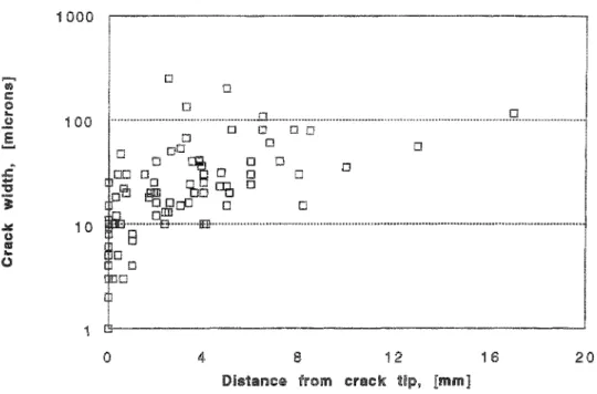
1000 0 Cl 0 0 0 0 00 0 0 00 0 0 ID 0 0 0 0 0 0 0 .:.:: 10 u (ij "-(.;I o 20 40 60 80 100
Fig. 18, Crack width at surface and midway for 17 corrosion fatigue
I''W'~U''~:'" versus 1000 0 Cl 0 Cl 0 0 0 Cl b~ Cl Cl "' ~ ~ 0 p 0 DD 0 DO 0
~
Cl 0B
Cl rIl ID Cl ~ ~ Cl ~ 1 o 2 4 6 10one
mm 12 10 4-, ... _'", .... /' /'o
, / , / / ' / / 0.5is
-":;;;.' '"Q .-'..
-/ ' / ' / " /" ... , ... ... 1.5 2.5 3Fig. 26, Crack width at three locations for one corrosion fatigue crack in
versus tip.
4.6.4 IGSCC
4.6.4.1 Ferritie low alloy steel
13 were
wan thickness and crack depth/wall thickness ratio is 1.0 ~ 23 mm, 5
-are In Fig. 21
surface and midway are plotted versus crack mcme,(] versus (11s1tarM;e
each crack is included graph. The crack width lll¥.lVQ.'~ inCjrea~;in2 depth/wall
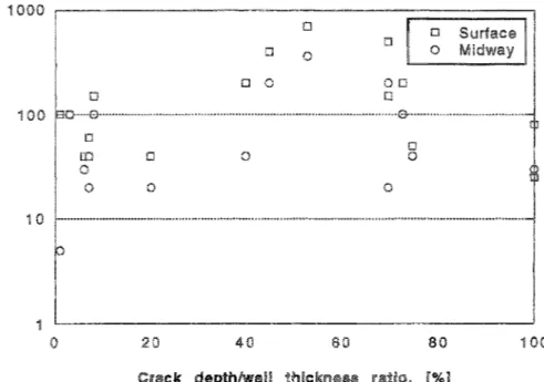
Cl Surrac \') Midwa 00 1-... , ... ,' ... , ... , ... , .... ,., ... ,', ... ,'"" .. , ... {.l ... ," ... " ... , Cl Cl o o o o \') o 10 ~".,.-... -"" .. ~ ... ~'""~ ... -.~ ... ' ... ' ... - ... , ... ,''''~ Cl El o o 0 1 o 20 40 so 80 100
Fig. 21, Crack width at surface and midway for 13 IGSCC versus: crack
1000 0 100 0 p Cl [] .=
...
Cl 00 Cl Cl Cl Cl 1'3 i .lII: 10 ~ "~ ~-
~ Cl P Cl Cl [] u ~...
0 ~ Cl [] 1o
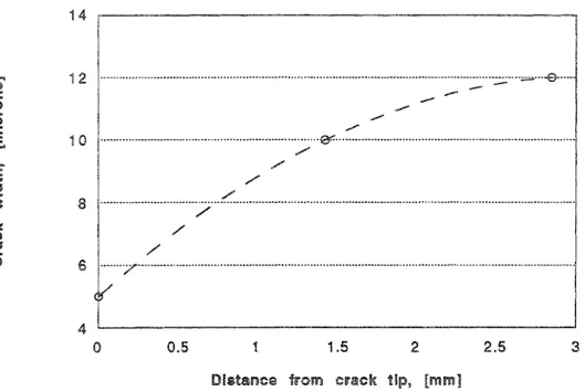
4, 8 10 12is mm, 8 are 80 60 J: ... "C1 i 40 .¥ ~ €C'
...
-,- --(.) 20 -(jo
2 3 4 5Distance from crack tip, {mm]
Fig. 23, Crack width at three locations for each crack versus distance
were
4.6.4.2
Staifl.lefS
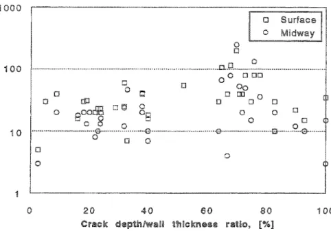
IGSCC cracks in stainless depth, 100%, steel The arecracks are from the nOll1-11UClear
iOOO 100 0 Cl 0 ..ii: 10 u «Il
..
Cl (,) 0 0 Cl 0 tJ 0 0 ODD [jJ 0D°
Cl Cl 0 0 0 0 0 20 40 60 SOCrack depth/w£'Ili thiekl'Hi!1!38 ratio, [%J
Cl Cl
100
Fig. 24, <:rack width at surface and midway for 37 IGSCC versus crack depth/wan thickness ratio..
70 60 , , 50 , ,
.
40 .~, J£ .... "0 30 i ",,-.
.,..- , .,..- . / ' ..ii: U 20 «Il...
(,) 10.
18' .0' ... + / ' ",.. / ' " , '-
-
-. -:;:-:--~ ,,~.- ~ .,,;::' -~/. in.
-'
-?;
;,"'-0 2 3 4 5 7D!st8lm::e from crack tip, [mm)
25, width at
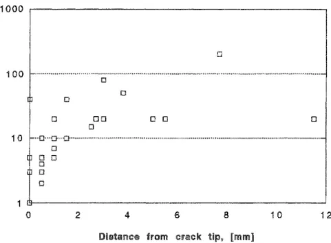
'1000 Cl 100 o Cl Cl Cl DD Cl Cl Cl 16 20
Fig. 26, Crack width at three locations for each crack versus distance
4.6.4.3 Nickel base alloys
Twelve were wall and
depth/wall thickness ratio is 0.3 - 8.56, 1 - 8.56 and 50 - %, respectively. results are shown in 27 through 29.
1000 0 Surface 0 100 D ,£
-'j 0 ~ 10 C.lI till...
4'.> 0 0 1 0 20 40 SO SO 100 Crtill©~ t~lc:tne$6Fig. 27, Crack width at surf'ace and midway for nin.e IGSCC cracks in Nickel base alloys versu"r.; crack depth/wall thickness ratio.
1000 100 0 Cl Cl D D 0 .9.., 0 I~ B 8 D DD i
o
at from crack tip.D .'" Cl Cl 0 0 0 :2 :3 4 5
~=---
...
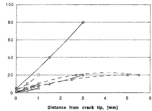
-40 - -30 '" ."."" '" " /' .-20 -x· .• . x 10 . . CUI 1Fig. 29, Crack width at three locations for each crack versus distance from crack tip. Four typical IGSCC cracks in Nickel base aHoys.
4.6.5.1 Ferritic low alloy sted
In aU, four TGSCC in ferritic low alloy were evaluated. in crack depth,
thickness and depth/wall •. u .. " ... ...,"'" is
are in Fig.
' ; c 0 (I Cl
...
o .2 0 g 00 .'Iii: 0 eJ III...
0 0 o 0 10 0 10 20 30 40 50 60 4 •.• -,,, .... ,-"" versus 1000 Cl 100 0 J:...
"Cli
J Cl Cl Cl .'Iii: 10 t.) lII:I..
0 J Jo
0.5 1.5 2 2.5 3Fig. Crack width at three locations for each crack versus distance froOm
:Jti. u
•
...
0 350 300 250 200 150 100 50 0 0 :2IJillltSlnCG from crack tip, [mm]
... ,...""iIJ,,, with ri""· .... t-I-.'"
3
thickness 5~16 mm and crack deptblwall thickness ratio 7~50%.
stainless
number of evaluated TGSCC cracks in stainless was range
crack depth/wall thickness ratio is 0.5-20 mm, mm
000 w 0 100 CJ 0 0 0 .I!i1 iO (,) «IJ 0 00
...
0 0 (',) io
20 40 60 80 100 ['Ye] versus 1000 0 100 0 0 0 0 0 0 0 0 0 10 .:a:: iJ 0 0 I:!I...
(',) 0 0o
2 .4"
El 10 at versuswere a scatter
1
... ""'"""'"", one a
five are "'",.'n"'",,,,,, liiOUI:.:e.cl cracks. is no dHferen{3e data
the two 'Tr;~"",(1 COl1Sequently all are <UiUCQM..U as one group range
crack depth/wall 'WtUI~2>..UvO" is 0.5 - 3 mm, 3 - 7.62 mm
i"",')!1,.U1..:! are 37. HIO 0 Surface 0 Midway o 0 0 ~ ~ .= 10 0 .... 'g i 0 1 o 20 40 60 80 100
Fig. 35, Crack width at surl'ace and midway fer three IDSCC cracks versus crack depth/wan thickness ratio.
o o i
o
0.5 1.5 2 2.5 o o 3 3.5 4~'ig, Crack widtb at three locations for each crack versus distance
from crack tip.
iOOO 100 s::. .... "D i .laC: !J 10 IJf$
...
u MidwayFig. 37, Crack width at sudace, midway and at crack tip for six IDSCC in
at were too
upper dashed scatter, the
are
'vVLU"/i:!>.iLVU U"~U:;lU'''''' data is considerable compared to the other two mechani..,ms .
... "" ... "'UJl.., ... and thermal stainless ,n,.,'.,''''_ see
depth/wall I:h1c.kness
In 41
along versus distance to the tip is shown. In both plots the mechanical and
reasonably data
Table 4, Cracli width statistics of fatigue cracks alloy
Number 6 I
3 5
deviation
800 100 €lOO 500 ;-... .;:: 400
-
!_ ... 'I':lI "fi 300 ... ..:=: c I'll .... 200 0 t .. · - -... - . ... 100 0 -- _ ... f···· f····r
1
!. -- -)
-_._--
... i- ...Fig. 38, Range of crack widths at surface (s) and midway (m) locations of fatigue cracks in ferritic low aUoy steels.
400 350 f··· 300 250 .::;.
-'I':lI 200 'i t···,
... .¥ c 150 I'll i···,
... ......
U 100 ! ... !-~- ... ---50 .. I""" f··· .. · ... .. ------
---0
Mech fat • s Therm fat - s Mach fat - m Therm fat - m
Fig. 39, Range of crack widths at surface (19) and midway (m) locations of fatigue cracks in stainless steel.
Cl! tl <i!II ....
...
::'I !Ill .... «> s:. .... "§ 'j JII: <C"
..
(,.) Fig. s:....
"
i JII: <C I'll...
(,.) 000 100 0 1 steel 1000 <> 0 <> - <? - ... ~ .. ~ ~ ~ .. ~ : .. "''-::''-~ ~ :: .• <>. -- - ... ~ " ~, 0 0 0 20 40 60 80 100Cl'l'lIck depth/wall thlci:.nees ratio, [%]
~idtb at surface for fatigue crack..~ in fenitic low alloy
versus crack depth/wall thickness ratio.
o <> <> <> <>
..-
.1> -,,0 0 _ . _ .. _ . .. • _ .. • .0-100~"·~·.··""··~-~··~~":·~··r-'~"·'.~--~"C"o"",,·-···· .. D .... ···· .. ·· .. ·· .... ···· .. · .... -· .. ·· .... ··· .. -· .. ·~ 0 <> 10 0<> - 0 -Meehan!celi 0 ---e ... Therm~i -.0- -Corrosion fatigue 1 0 2 :3 4 5 S 7 8@ u !Il:I
-
'= ~ lIIII .... I;\J &.....
1Z "it ~ e !Il:I...
U .c ... :si! 11 1000 0 0 100 0 0 10 1 0 20 40 60 80 100 120Crack depth/wall thickness I'l!Itio, [%]
at in ve:rsus HlOO o o ~ ... ~ 100 ~'·"·'·'·""""··"··"'···7~;···"···"·'"·=--··'·~·;·" ... . o o o 00 o ~ 10 mn~Cr···8c ... '" ••..•....•... ····~7···'"···"'··· ...•.•... ~ e !Il:I
...
U 15---J
o
4- 12 Hi 204.6.8,2
6-300~I
, -250 .... , 200 150 , ... r -..lo!l 100 (.j ~ i .'., ......
- -0 50 - -r - - --
- r - - - -0 r - - boo::-=- ' - --
-
- ' -~- ' - - --
-~ ~ -=
;::::;;:;:Table Crack width statistics of IGSCC for low aHoy steel and steet at surface [J..IID.] IGSCC 4 100
inside the crack [
IGSCC
nickel base
2 1
260 20
1
Table 7, Crack width statistics of IDSCC and IGSCC for nickel base alloy.
4.6.9 Literamre data on crack width
measurements
pipe means a low was
mea-sured by ultrasonic or by testing, examination.
Statistics the crack width measurements and plots on crack width versus
depth/wall are shown Table 9 and 45 and 46, respectively.
measurements are
were
LfaI.J.A .... '-'i!I in two 14I"n,1",,'I"C' Ine!alIlog:rap,mc examinations
was measured both at
in at
the crack. there no COIrellittlclfi between crack
width. crack and pipe dimensions. a given crack depth, width is assumed to
be controlled by bending moments. applied and he suggest the
to presen.rea as a
water reactor
not are
cornp~trin:~ data
.... V'.i"'M .... JI.~'U of this comparison is that crack measuremems on me~uu!ogralJ!mc
sam-[5] and an good accuracy as measurements made
metal sun:ace
cracks were turn
on
to-gether with some data points from thermal fatigue in cast austenitic stainless steels and corrosion fatigue Type stainless steel. cracks were produced laboratory and the specimens used were of equal or almost equal thickness. The crack width
mea-surements were all made at the crack/surface The width are
re-plotted versus depth/wall values are
more
narrow thermal crack
corrosion fatigue cracks. may partly be explained by the fact that all the width
data DoctorlStenefjlill were obtained in laboratory where both loading and
environmental conditions were well controlled. The major part of the cracks evaluated in
are attack
IIi (.) Q
-
...
:::I 1111...
Q .l:...
:E ~ .Ill! I1J Q...
0stainless steels. Compar.ison between results of this work and literature data, [2], [3] and [5].
200 150 100 -... -...
--- --- --- --- , ... " ... 50 -"--
.... - --- -----_
... --0 {2J [5]
Fig. 45, Range of crack widths at su.rface of IGSCC cracks in austenitic
0:;"'''' .... ''' of [2],
1000 HiD 0 tJ
-
0 II:i .t:....
10 o:JD 0 "a i 0 ~ ~ I'll..
U 1 0 20 40 60 80 100Crack thickness ratio,
at versus 1000 ,
,
0 0 0 ri 100 u III .'"' 0 0 0 0 u 't: ;::, 0 0 I@ ...."
0 ~ 0 0 0 0 J:: 10...
~ "a i .iiII: (,l III..
0 J. o 20 40 60 80 iOO [2]..... Cl! .:::;
...
"'a'i
.lliIl I\lI Cl!...
0....
!::\I .:::;....
1:1 i .lliIl Q I!%...
0 o o -+ -+ 0 0 10 -+ 0 0 20 40 60 80 100 Crack: thickness iOOO,---~ 100 <> 10 1 0 20 40 Crack: at versusof
o 0 SO o o TtU!lIrm#i1 COl"rolllon Mechanicai 80 th!cknlillli [%] 100HIO _., f·-~~--- ... --.- ....
ao
_
... c·-_.' >.-60 r' '., ... ' .... f-. .. -.... !\'I 40 r' ~ ... - - - .. -.c....
"
'[it f-. ... , ... f·-.ill: 20 0 f-' r··· f·'···,
... «flY...
--,
- --
.. -,",,-() r' --- ---,---0 J J stainless steels [6].As mentioned previously the crack width strongly dependent on the stresses acting
pe!'pel:l(:H~cm;ar to When cutting out a
often is a:n]~u~a due to
or
crack width, and NDT rl"""'~n+...,.
CaIlrlea. out Brickstad in 1991 crack
closure was divided two categories. namely, I1P"r1Irp induced and crack gro\vth induced
"'J.'-,"' ... ,.., the by
hVldrCIStiLtic loads, or "'U'''''U~'''''''
as, weld residual stresses or residual stresses forming. Crack closure during
crack growth occurs to local plastic residual strain in the of the crack surfaces
"'."'..,""" ~ .... "".ul""~ ID a cirl;;Wlrnfe]rentiru
u"", ... ' .r,r",.,"",..., iV'''''' ... ID :a cmoollnterential
in service __ ~ .... ,.., shut
bent
CQJ1W1U0I1S at
stress
occur
a nuclear power plant.
positions along pipe
... "",.",.fh un •. ",,,,,,", ... v.:), ... was c!a:lme~\1 to be well iIr .... ,., .. ",...,
more difficult to pre~ru.c:t •... ~,J ... !F'.u. ~u'"'.uu, ... fatigue at LUUlkU.l§
where water different temperature mix. was found possible.
Considering estimations, the of crack closure must be accounted
where the
SlU.nlectto severe ti"lP'lrm;:!
Crack width According to
mechanical
are presented ';:!v"'I'1.VU 4.6.9. A reasonably
is 'I.',JI ~iCUJ.tJi.i3tt",U
....
III J::.....
"
i :;,t."
fl'J...
(.) 400 350 G@it!l. 300 250 2:00L _
!.l
i' 150r
I I-I ~~~~~~~.~ ~ ••• n~~~"'~U'~.~ 11 1 100r
50 0s:
~ E ~ w ~ ~ "? "'" ~ J5 ~ "" m Z Z u "? "'-' "." ~ ,~ ~ (,.) "'" u i$ "'?.,.,
~ .;<! JijB
u8
~
u Jl!8
i
1
J
~
""..§
&; (,.) V.I (,.) 0J
~ <I!l "" ~ ~ Ill) Cl ''"' Cl 9..
" ;:::; ,... on the surface of fatigue and stress corrosion cracks.a:
~ "'"""
"., "?B
K...
""
v.> 52 £a4.7 Crack surface roughness
merumrements
on
4. '1.1 If'atigue
evaluation seven mechanical fatigue, therm.al fatigue 20
... ~ .. "., ... ' , ... ",,,.,-., are Table
.lau~"",",· ""u ... A.a show lower and less i:>'\.',",''''"",lVU compared to 'v, ... "'''' ...
fatigue Cl'acl.(S highest 4-values were measured mechanical fatigue cracks, while
evaluation fatigue thermal fatigue are
shown in Table 11 and Fig. 52 and 53. Mechanical fatigue cracking in stainless
a comparable roUg.!l1'1lesS to ferotic steel. One data
212 !lm, U"e.~'''''A than the the scatrer this data group
more sca1~r~~a to "'''''u''''',",
Cracks
7
260 200 1·· ... • ... · .. ···· ... ••··· •• •••· .. ·•• .... • .. ···.. •· .. •••• ...
-...
I!@ i:: 150 ,-" ... 01..
(» "E ... N 00 .."." .. I··· ... tt 50 ... ~---1
~ \) 1000 800 ... I· .. ··· .. ';' 600 c: ... 0..
(3 'E...
~ 400 .. .. _ ..._
.... - .... -0 ...: 200 .. -.. ! .... I " ' ' ' ' -- -1 ~---.--lFig. 53, Comparison of correlation length, of fatigne cracks in
cases is .."h,",p''Mu·£1 below deviation evamiilClon of less 13 and
rou.g.!ll1!ess and
1
250 200 _ _ _ " ' . 0 " _ _ 150 f .. • .... • .. - .. 50 , ... " .... i .. ·"·· i ... _ • • • 0 . . . ..
---
..--.--IGSCC-SS I(.;iSCC·Ni iDSCC-Ni
base alloys in Fig.
same data illUluns are compared 57.
in
300 250 ...., :;:00 ~ 1:: (I
..
!J'e
HiO....
IS m: tOO 50 0 ""...
"" ~...
qi
~~
~ 12 ~ :! ""' tl u u1 1
J
""g
'"
u W> ~~
::2 ::2 Sf! A.4htwo areas rest were the lnItuenCe
11lttuelrlCe on se~re~!H IIletJtlO(lS to measure
are many .... ..,.UUU ... 'JA .... which depend on
measurement is .uu" .... " .. ""' .... '.5 methods are 1-''''''''''''''''''''''' measurement on a
a surface roughness or measurements on a
over a cross section The most common measW'es are and
surface measurements on ratl,gue test spt::cu:neIlS of
auste-stainless and ferritic low
median
derived
ness
25 20 -... , ,-... 'i' IC H> 0
..
Q!
'Ii 10 -a: I !i [1]-CSFig. All data are converted to
Ra
forwith dam established
exc~'Dtion is
roughness,
stainless the local data reported in [9] are mLlch
work. a median value 1 Jlm to
I
r
-I
~---f
are "i'\f1,'~"'"
agreement
lIi:UI~" MtWAI>:n :; and
HiO 7: I: C
..
u!
100 Ii' a; 50 0 ] .s:;!
I
] ] ]~
1
""
~ it3 5: ~ uj
"'t ~ ~i
m tl ~!
sa
i
"'"sa
60~---T---·---4 0 -! ... o •••• o • • o • • ooooo • • o _ _ _ ._o.oo . . . . o_o_~
30
1
~M.~'~ ___ .~~ ... ~~_I
1- -20 i 10~IU
0 00 en <;I) """t1
<n ~ ~ U <h U "'i' v" ~ ...g
uB
u Ji ,i Ji 'lll (1) ""'8
~ u~
j
J J
~ ~'"
... ~ y:; ~ ~ ~-
sa
pe:rfo:rm:ing a ... <Lv accurate ""'1'"<""'" conditions. component !llDllelltSlGlns. length, along crack • amooot
1 2 3 4 5 6 7 8 9 cast ompOIlents in Piping aeu~cn.~:>D of plemelnt to 1991.
hhmUfic"H!«)gl Crack mecnaoi$m
Ml!tef~a! gr:ade Materia! cOl"ldmll!1
Crack dim@flsicl'I [Iltml
to .• tnleknes$ thickne-s Numool1' of cr~ci(s M aU::f(!scof»h: brallchh;t{l 10 Amount of (utidli';s Surhlc(;!! 1
I
Sketci'l R",fliilUHIC.e Crack iOClltio!1 M;mteriOlI group form Surface C·S Ilattem dilt~jlnce Micl'o-struchlr£, L {mm] Midway 3o
Crnek rndius Midway 1o .... er crack location <ll"ld shape
\
\
\
\
\
Tip Tip\
\
\
Appendix 1 A, G ImmJ 2 0 1\
\
\
\
\ 30\
\
\ \
\
I I I I I I I I I I I I I I I I I I I I I I I I I I I I I I I I I I I I I I I I I I I I I I I I I I I I I I I I I I I I I I I I I I I
SKI Report 95:70
Research
Crack Characterisation for In-service
Inspection Planning
Peter Ekström
Jan Wåle
November 1995
ISSN 1104–1374 ISRN SKI-R-95/70-SE S T A T E N S K Ä R N K R A F T I N S P E K T I O NSwedish Nuclear Power Inspectorate
POST/POSTAL ADDRESSSE-106 58 Stockholm BESÖK/OFFICEKlarabergsviadukten 90 TELEFON/TELEPHONE+46 (0)8 698 84 00 TELEFAX+46 (0)8 661 90 86
E-POST/E-MAILski@ski.se WEBBPLATS/WEB SITEwww.ski.se