Mobility management for software
defined wireless sensor networks
Christian Nevala
cna13001@student.mdh.se
Mälardalen University
Västerås, Sweden
2016-05-25
Supervisor:
Maryam Vahabi
maryam.vahabi@mdh.se
Examiner:
Abstract
By advancing technologies in both hardware and software, it is possible to support more complex applications. Wireless Sensor Networks (WSNs) comprised of tiny sensing devices with wireless radios are the key enablers for future Internet of Things (IoT) applications, where collecting measurements and delivering them to their destination is the most important task. In traditional sensor networks, sensor nodes were typically stationary and each node periodically measured and sent data to the next predefined router. However, in current applications, some nodes are expected to move. For instance, in health monitoring applications, where patients with sensors attached to their body are free to move in the hospital or their houses.
Software Defined Networking (SDN) is a technique that was conventionally used in wired networks, and recently was used in some wireless networks, such as cellular and wireless local area networks. The idea of SDN is to provide more flexibility in the network by getting the advantage of re-programmability of the network devices during run-time. In networks based on SDN, the control plane is shifted from the infrastructure to a higher level in order to provide re-configuration. The controller decides on updating forwarding rules by getting some feedback from nodes in the network. In wireless sensor networks, the feedback may contain information related to the link quality and available resources such as battery level and the location of the sensor node (number of hops away from the sink).
In this thesis, a study of several relevant SDN-based architectures for wireless sensor networks is given, outlining the main advantages and disadvantages for each. In addition, some mobility solutions in sensor networks such as localization, routing and hand-off algorithms are explored. One of the drawbacks with SDN is that it was originally built for wired networks there experience with mobility does not exist. Thus the thesis considers the possibility to use SDN solutions in WSN were certain applications are in need of mobility. Finally, the thesis propose mobility solution for sensor networks that takes advantage of SDN and uses a hand-off algorithm. In fact, the hand-hand-off mechanism is achieved by means of control message exchanges that is supervised by the controller.
Table of contents
1 Abbreviations ... 1 2 Introduction ... 2 2.1 Background ... 2 2.2 Motivation ... 2 2.3 Problem Statement ... 3 2.4 Method ... 3 2.5 Expected outcome ... 3 3 Theory ... 4 3.1 Basics on SDN ... 4 3.1.1 Benefits of SDN implementation ... 5 3.1.2 OpenFlow ... 53.2 Mobility solutions in wireless networks ... 6
3.2.1 Localization-based mobility solution ... 6
3.2.2 Mobility solution based on hand-off mechanism ... 6
3.2.3 Mobility solution based on Routing ... 6
3.2.4 SDN-based mobility solutions ... 7
3.3 OpenFlow challenges in WSNs ... 7
3.3.1 Handling packets in WSNs ... 7
3.3.2 TCP/IP connection in WSNs ... 8
3.3.3 In-band signaling in WSNs ... 8
3.4 Different proposed SDN-based solutions in WSNs ... 8
3.4.1 Software-defined sensor network ... 8
A Software-defined radio ... 10
B Wireless sensor operating systems ... 10
C Over-the-air-programming technique ... 10
D Field-programmable gate array technique ... 10
E Pros and cons of the solution ... 10
3.4.2 Smart wireless sensor network based on software-defined networking ... 11
A Middleware layer ... 12
B Application layer ... 13
C Pros and cons of the solution ... 13
3.4.3 Software-defined for clustered sensor networks ... 14
A Interconnection between domains ... 15
B Pros and cons of the solution ... 16
A The SDN-WISE approach ... 17
B SDN-WISE protocol architecture ... 18
C Topology discovery ... 19
D WISE packet description ... 19
E How packets is handled by the Forwarding Layer ... 20
F A highlighting scenario of the SDN-WISE solution ... 21
G Pros and cons of the solution... 22
4 SDN-Based Mobility solution ... 24
4.1 Architecture ... 24
4.2 The mobility approach ... 25
4.2.1 Intra domain mobility solution ... 25
4.2.2 Inter domain mobility solution ... 27
4.2.3 Mobile sensor node mobility algorithm ... 29
4.2.4 Stationary sensor node mobility algorithm ... 29
4.2.5 Domain base station mobility algorithm ... 30
4.2.6 Global controller mobility algorithm ... 31
5 Conclusions and discussion ... 33
5.1 Future work ... 34
1
1 Abbreviations
AODV Ad-Hoc on-Demand Distance Vector
AP Access Point
API Application Programming Interface
CH Cluster Head
DBS Domain Base Station
DSDV Destination Sequenced Distance Vector
DSR Dynamic Source Routing
ForCES Forwarding and Control Element Separation
FPGA Field-Programmable Gate Array
FWD Forwarding Layer
INPP In-Network Packet Processing
LTA Localization and Tracking Algorithm
LTE Long Term Evolution
MANET Mobile Ad-Hoc NETwork
MME Mobility Management Entity
NOS Network Operating System
ONF Open Networking Foundation
OS Operating System
OTAP Over-The-Air Programming
RSSI Received Signal Strength Indication
SDNCH Software-Defined Network Cluster Head
SDCSN Software-Defined Cluster Sensor Network
SDN Software-Defined Network
SDN-WISE Software-Defined Network for WIreless SEnsor network SDR Software-Defined Radio
SDSN Software-Defined Sensor Network
SGW Serving Gate Way
TCP Transmission Control Protocol
TD Topology Discovery
TM Topology Management
TTL Time To Live
UE User Equipment
WMN Wireless Mesh Network
2
2 Introduction
This section mainly focuses on the importance of mobility solutions for WSN. First, we discuss the motivation behind this thesis and then elaborate on the problem formulation/statement. Finally, we explain the method being used to solve the mobility issue in WSNs and the expected outcome.
2.1 Background
With more devices becoming smart and in need to be always connected, providing pervasive wireless networking becomes essential. These devices also need to be able to move without losing connection, which makes a good mobility solution important. This is especially important in Wireless Sensor Networks (WSNs) with limited resources and the need to support mobility in various applications. Solutions for wireless networks is growing, but because of the complexity of these solutions, it is not possible to apply the same technique developed in Cellular and Wi-Fi networks.
The rise in the number of smart devices makes it possible to create new applications for monitoring and control of different phenomenon that will help us in our daily lives. Applications that make it easier for health monitoring, industrial automation and smart cities. But when it comes to implementing more devices into the network, a more efficient way for network management is required. This problem can be fixed with the Software-Defined
Networking (SDN) [1] architecture.
The SDN architecture provides a control layer, which is logically centralized, and maintains a global view of the network. The controller provides flexible configuration and network management, it also optimizes the number of network resources via automated and dynamic software programs. SDN and OpenFlow (the most common standard used by the SDN architecture) [2, 3] have been tested successfully both for wired networks and Wireless Mesh
Networks (WMNs) [2], but have not been fully utilized yet in WSNs. Some efforts have been
done to extend the SDN concepts to WSNs [3, 4], however, they have not addressed mobility solutions in their architecture design.
2.2 Motivation
The importance of a mobility solution for WSNs is getting bigger because of the increase of WSN applications. Clinical health monitoring of patients in hospitals and elderly people in houses is an example of sensor networks with mobility requirement. This kind of applications should consider the fast delivery of a hazard situation to the healthcare provider. Another example can be automation applications in the industry, where, mobile robots are involved in the manufacturing sites. If a production line stops working because of the malfunctioning of a robot, it will be known as a very expensive loss. Hens, a solution for a functional and flexible mobility architecture is needed so that unnecessary disruptions will be avoided and critical messages can be sent in a timely manner.
3 2.3 Problem Statement
Mobility management is one of the big challenging problems in wireless networks. Because of the nodes moving freely in wireless networks, an efficient way to switch between different
Access-Points (APs) is of crucial importance. In WSNs with high resource limitations (i.e.,
power, channel bandwidth and processing capabilities), providing mobility management becomes more severe. Various techniques have been designed to support network connectivity in WSNs when nodes are moving. SDN gives better flexibility and management that mobility needs, but haven’t gained a fully utilized mobility solution due to its wired network origin. This thesis mainly focus on SDN-based solutions, different mobility methods in WSNs and explore the benefits that can be gained from implementing SDN in WSNs in regards to mobility management. Questions to be handled in this thesis work are as follows:
Is it possible to set a mobility solution in WSNs using SDN?
What is the biggest holdback when it comes to implementing SDN in a WSN? How can we reuse the existing SDN solutions in WMNs and WLANs for WSNs? 2.4 Method
In order to provide mobility support in WSNs, we first browse a number of solutions that have been proposed to support mobility for wireless networks in general. We will then narrow down this area and focus on the existing SDN-based solutions in other wireless networks that are used today. This will be accomplished by reviewing the related works oriented to mobility solutions with SDN. Next, we have to identify the challenges of applying SDN-based solutions on WSNs. With all information regarding SDN solutions, SDN in wireless networks and by considering the limitations in WSNs, a proposed SDN-based mobility solution for WSN will be constructed.
2.5 Expected outcome
The main outcome of this research is a comprehensive review on the use of SDN in wireless sensor networks, and the possibility of applying this solution on the WSN. We then explore the existing SDN-based solution for WSNs and provide a qualitative comparison between these protocols. We will also review the related works on other mobility solutions for WSNs, and define an algorithm that supports mobility in WSNs based on the SDN networking architecture, while considering their main limitations.
4
3 Theory
In this section, we will first describe the basics on the SDN architecture, the potential benefits of using SDN-based solution, and more detailed information of one standard used by one of the applications interfaces in SDN called OpenFlow. We will then explore different mobility solutions for wireless networks, in general and then look into an SDN-based mobility solution for wireless mesh network. We then look into the limitation of WSNs in implementing OpenFlow standard. Finally, we will discuss currently proposed SDN-based solutions and discuss the possibility of SDN-based mobility solution in WSN, considering its limitations. 3.1 Basics on SDN
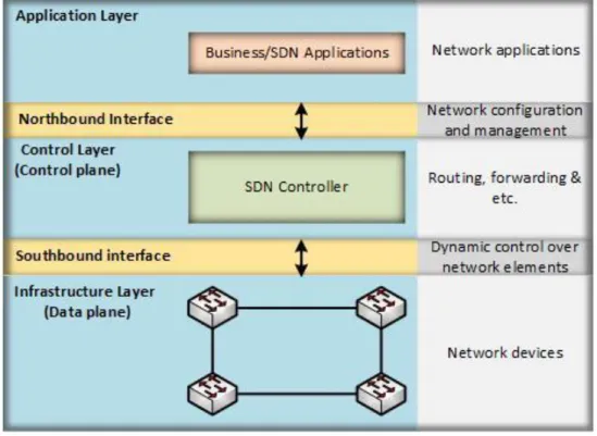
The SDN architecture consists of three layers: (i) the Infrastructure Layer (Data plane), (ii) the Control Layer (Control Plane) and (iii) the Application Layer [5], see Figure 1. The Infrastructure Layer also known as the Data plane, consists of the forwarding elements (e.g., switches and routers) of the network. The infrastructure layer, also has the task to monitor the local information and statistics from the switches and routers [5, 6]. The control layer is a software logic that provides the forwarding rules for the Infrastructure elements, and defines the network operation and routing [5]. Some refer to this logically centralized control unit as the Networking Operating System (NOS). The separation of data plane and control plane allows a network operator to control the network behavior from a single high level program. The Application Layer handles the monitoring applications in the network, which can introduce new features to the network. New features that could include new information about security, manageability and forwarding schemes [5].
Between the Control Layer and Infrastructure Layer, is the southbound interface located, which most often uses the OpenFlow standard which is the most used standard today [5, 7].
5
The task of the southbound interface is to bridge control and forwarding elements through a well-defined interface. Other standards used in the southbound interface are the Forwarding
and Control Element Separation (ForCES) framework [8] and the SoftRouter architecture [9].
This report will not go into detail about these two standards, instead, it explores the OpenFlow standard since it is sued in a number of SDN-based solutions for WSNs.
The Northbound interface is located between the Control Layer and Infrastructure Layer. Northbound gives fine-grained control over the switches and let the applications and the overall management system to program the network according to their required services [5]. 3.1.1 Benefits of SDN implementation
By implementing SDN in the network, it will make the network management less complex and provides better flexibility in scalability and mobility support. This is mainly due to the separation of data plane from the control plane and the simplification on the implementation of new applications in the network. Other benefit achieved by SDN implementation is related to the capability of SDN in providing resource management. With SDN implementation, different applications are able to share same network infrastructure. The access of each application to the forwarding elements is managed by the control unit. In fact, this is feasible because the controller has the global view information of the network and it knows the requirements of the application. So the SDN makes applications have precedence over the conventional routing policies. This will make the policy decisions more consistent and effective in the network. It also gives a more flexible way to implement new functionalities in the network. These benefits in summarization will make it simpler to modify the policies in the network. It will keep high-level policies intact by using a control program which react to changes of the network state. Finally because of the centralized controller having knowledge of the network state, the development of networking applications, functions and services will be simplified [10].
3.1.2 OpenFlow
The OpenFlow protocol is the most common standard used for the southbound interface, which was mentioned earlier and was standardized by the Open Networking Foundation (ONF) [11]. The main purpose of the OpenFlow protocol is to provide an interface for the interaction between the Infrastructure layer (OpenFlow-compliant switches) and the Control Layer (Controller). The OpenFlow architecture consists of three “concepts”, a data plane built by OpenFlow switches, a control plane that is composed of one or more OpenFlow controllers, and a secure control channel to connect the control plane to the data plane provided by the southbound interface [5].
An OpenFlow-compliant switch is like an original networking switch that forwards packets according to flow table entries (also called flow rules or flow entries). These entries consist of three fields: (i) header field that specifies which packets the entry is applicable to, (ii) counter that collects statistics about flows, and (iii) action that specifies how packets from the flow should be handled [5].
6
In the OpenFlow protocol, three classes of communication exist. The first class is controller-to-switch, which takes care of feature detection, configuration, programming of the OpenFlow switches and retrieving information. Asynchronous communication is the second class and is initiated without the controller’s solicitation by the OpenFlow switch. It is used to inform the controller when packets arrive, when a state change within the switch, and when errors occurs. The final communication class is symmetric communication and is initiated without the controllers and OpenFlow switches solicitation. Symmetric communication includes hello and echo messages, which is used to check if the control channel is still available in the network [5].
3.2 Mobility solutions in wireless networks
There are several research works that provide mobility management based on routing, localization and hand-off mechanisms. These approaches are performed in a distributed way by the interaction of mobile nodes. SDN has been initially introduced to enable the flow-based routing for the Wireless Mesh Network (WMN), which is a multi-hop wireless network [2]. In this section we will provide examples of any of these types of mobility management in wireless network.
3.2.1 Localization-based mobility solution
One of the most common mobility solutions in wireless networks is based on localization, which stands for finding or estimating the geographical position of a node. The localization mechanism is divided into two tasks of (i) registration and (ii) call delivery or paging. In registration, a wireless node periodically sends out its current location to the network, so the location database can be updated. In the call delivery phase, the information from the location registration is used to query the network about the node, so it can successfully be connected. The localization mobility management method is used for nodes with limited mobility requirements [12, 13].
3.2.2 Mobility solution based on hand-off mechanism
Another way to handle mobility is by using hand-off mechanisms. For a mobile node, hand-off means to change point of attachment from one AP to another. There are two classes when talking about hand-offs: (i) hard hand-offs and (ii) soft hand-offs. In soft hand-offs, multiple radio channels can be used at the same time, which make it possible for a mobile node to communicate with several APs at the same time to check the quality of each link, while data is being transmitted to the AP that is serving at the moment [14]. In hard hand-offs, only one radio channel can be used and before the hand-off can start it needs to stop its data transmission [14].
3.2.3 Mobility solution based on Routing
Another solution to handle mobility is based on routing mechanism. We will look at three protocols used for Mobile Ad-hoc NETworks (MANET) and their mobility solutions. The first protocol is Destination Sequenced Distance Vector (DSDV) [15] that uses sequence numbers for each entry in its routing table. Every node in the wireless network maintains a routing table (similar to routers and switches). In this table, it stores information for each destination node
7
possible from the node. All of the entries in the table are marked with a sequence number. If a new sequence number occurs and is higher than the old one, the routing table will be updated [16]. The second protocol is the Dynamic Source Routing (DSR) protocol [17] which is an on-demand routing protocol that is based on source routing. Whenever a node sends a packet, it first checks if a route to the destination still exists and have not expired. If the route is too old, DSR will start the route discovery phase. Route discovery is done by the protocol by sending a request message to all nodes to see if any of them know the route to the specified destination. If none of the nodes have any route to the destination, DSR will add the route to the node sending out the request messages route record [16]. The third routing example is the Ad-Hoc on-Demand Distance Vector (AODV) [18]. AODV is an updated version of the DSDV protocol, which keeps the amount of routes in the network saved in the routing table. Instead of saving routes in the routing table, AODV creates routes on-demand, it does this with the sequence numbers used by DSDV and to find routes it uses route discovery the same way DSR does [16].
3.2.4 SDN-based mobility solutions
An example of a SDN-based mobility solution is addressed in [19] by Looking into the Long
Term Evolution (LTE) Femtocell network. To take care of the mobility coordination LTE sends
traffic via the Serving Gate Way (SGW), which guarantees seamless communication when switching between APs. SGW together with the User Equipment (UE) and LTE Femtocell perform hop-by-hop signaling in order to handle session setup, reconfiguration and mobility which are performed by the Mobility Management Entity (MME). MME is the main component of the LTE architecture, and is responsible for access control of the network, radio resources, mobility, roaming, keeping location information of the UE, and giving load balancing to the SGWs [20]. In this architecture combining the control plane and data plane for nodes that join the network requires high signaling, which SDN is used to facilitate the process. One proposed solution to enhance this architecture with SDN is proposed in [19] by using local controllers for local decisions and global controllers for global decisions with the OpenFlow protocol.
3.3 OpenFlow challenges in WSNs
Implementation of SDN and the OpenFlow standard in WSNs requires considering all the inherent limitations of this type of network. OpenFlow standard was originally built for wired networks and it was mainly used in data centers, cellular backhaul, enterprise Wi-Fi backbone and WANs. Some differences between these types of networks and WSNs exist which makes it challenging to employ SDN in WSNs. In the section, we discuss the limitations and problems that needs to be addressed when implementing SDN-based WSNs.
3.3.1 Handling packets in WSNs
In contrast with WSN, which is more data centric, in SDN, packets are transmitted in flows. A flow is a customizable/programmable set of packets that is sharing the same type of properties which is specified by an entry match in the flow-table (more details on the flow table are available in subsection 3.4.2-A) [3]. Most of the time, this match only consider the first two octets in the IP address of the packets. To create flows, OpenFlow uses the IP
8
addressing scheme and bases matches on the source address, destination address and MPLS label in the header. The problem that will arise with implementing OpenFlow is that WSNs are looking at the data packet type instead of IP-address. Essentially WSNs look after data of interest instead of looking where the packets are coming from, or where they are heading [3]. 3.3.2 TCP/IP connection in WSNs
The southbound interface, which usually uses OpenFlow protocol, acts as a bridge between the data plane and the control plane. Thus, SDN architecture decouples network control and data messages, enabling control plane to become largely programmable and the underlying infrastructure to be abstracted from applications [5]. The control information that is created between the Infrastructure layer and control layer is sent via an OpenFlow channel. This channel is an end-to-end connection and its main purpose is to transmit control messages between these two layers. This channel exists mainly so that the control traffic isn’t giving the network a bigger overhead than needed, moreover, a bigger overhead would just bring more problems because of limited energy resources. This channel is reliable on a TCP/IP connectivity mainly so it can give a reliable in-order delivery of its messages. However, current WSN implementations are unable to support TCP/IP connection, which means that there is a need for designing a reliable communication channel between the controller and the infrastructure [3].
3.3.3 In-band signaling in WSNs
In SDN, the OpenFlow uses an out of band signaling mechanism, which means that, there exists a separate dedicated network for the OpenFlow traffic. This is unpractical in WSN, where it forces the OpenFlow channel to be hosted in band, which essentially means that all the extra control traffic generated because of the decoupling of the data plane and control plane will be handled by the WSN. This will increase the need for more energy usage by the sensor nodes, which requires a careful design to provide an efficient way for hosting the OpenFlow channel [3, 4].
Due to the inherent characteristic of WSNs in terms of limited resources of bandwidth and energy, it is crucial to provide energy conservation mechanisms. Data aggregation or decision fusion are some examples of in-network processing that can help in order to reduce data transmission [3]. This feature has been neglected in SDN architecture, while it can benefit WSNs.
3.4 Different proposed SDN-based solutions in WSNs
This section will provide four detailed descriptions for different proposed SDN implemented solutions in WSNs. After the description of each proposed solution the advantages and disadvantages of each solution will be discussed and conclusions will be drawn regarding the merits of each approach.
3.4.1 Software-defined sensor network
In [21] the author propose the Software-Defined Sensor Network (SDSN) architecture, which is a combination of SDN and Software-Defined Radio (SDR) [22]. With this solution they argue
9
that it is possible to reuse a sensor network by dynamically reprogram it for different sensing applications via the Over-The-Air-Programming (OTAP) technique. This will increase the flexibility of the sensor network and will at the same time reduce the deployment cost of new sensor nodes. The reprogramming of the sensor node should be done dynamically whenever a request for it arises.
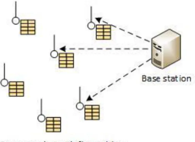
The SDSN architecture consists of a control server and a number of sensor nodes. In order to deploy a new task in the network, the control server sends out the programs necessary to perform the new task. To make it possible for the sensor nodes application to be customized at any time, the control server provides a role generation (generated by the scenario compiler based on a scenario description) and delivery mechanism. These specifies the needed functions to be activated in the sensor nodes for the new sensing task. The sensor nodes then gets a new task delivered via wireless communication so that they behave according to the new task [21]. See figure 2 for the overall picture of the process.
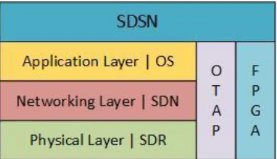
Logically the SDSN architecture can be divided into three layers which have one defining technology. (i) The physical layer which use SDR, which is responsible for the physical layer, and provide the interoperability in networks with different radio technology. (ii) The networking layer which use SDN and handles the data transmission in the network. (iii) The application layer which use the Operating System (OS), and handles all the sensing tasks (role programs in the network). The combination of Over-The-Air Programming (OTAP) and the
Field Programmable Gate array (FPGA) enables the software-definability in the layers of
SDSNs [21]. See figure 4 for the logical view of SDSNs architecture.
Figure 3 a logical view of the SDSN architecture. Figure 2 Software-Defined Sensor Network Architecture.
10 A Software-defined radio
Software-Defined Radio (SDR) is the technology used by the Physical Layer in SDSN. Its main
function is to sense the vacant spectrum bands and based on the information, change the parameters dynamically when the option is available [21]. Because the majority of sensor nodes is communicating through wireless medium, this can improve the efficiency and utilization of the spectrum significantly.
B Wireless sensor operating systems
Used as the main technology by the Application layer is the OS. Because of sensor nodes having resource limitations in comparison to regular computers, the OS needs to be less complex to save the resources. Some Operating systems that have been proposed have had this in mind when implementing different features. One OS for WSN is for example TinyOS [23] which is widely used today, mainly because of it not being in need of a big amount of memory.
C Over-the-air-programming technique
Over-The-Air Programming (OTAP) technique is an important technology of the SDSN. It’s in
charge of performing the role program delivery, control message delivery and etc. What OTAP is referring to is how to perform various methods of distributing new software in networks with wireless communication. Because of the increase of wireless nodes in society such as mobile phones and etc., have the popularity of OTAP increased and new standardizations with OTAP in mind have been established. OTAP have also increased its popularity in WSNs, this because of WSNs consisting of hundreds of sensor nodes which uses wireless communication [21].
D Field-programmable gate array technique
Field-Programmable Gate Array (FPGA) technique is an integrated circuit which have the
possibility to have its processing logics configured after manufacturing. FPGA consists of logic
blocks which are connected with each other with reconfigurable interconnections. These
blocks can perform operations from logical operations such as AND or XOR to more complex functions and analog processing. FPGA is an important part of SDSN because of it being reconfigurable and also being energy efficient. The energy efficiency comes from that FPGA can take over energy heavy tasks such as encryption and decryption from the micro-controller [21].
E Pros and cons of the solution
The biggest benefit of the SDSN solution is the ability of reprograming the sensor nodes according to a new application requirement, when a request is given by the OS. This ability makes it easier to manage the network and solves the policy issues. Reprograming the sensor nodes in the network, makes it possible to give new functionality to different sensor nodes in the form of rules. This at the same time makes it possible for new sensor nodes with different monitoring applications to enter and become part of the network. They claim that the OTAP technology solves the control message broadcast problem, this can also be useful for
11
OpenFlow based approach in order to update the sensors’ flow-table entries. The energy problems can be reduced through the FPGA technology which can take care of energy consuming tasks in the network. SDSN solves the overlapping problem that could occur in WSNs with SDR, which will give the network the possibility to structure a more efficient WSN infrastructure. This by checking the different spectrum of bands to see if they are vacant and able to be used.
A big problem with the SDSN architecture is that it is not fully tested and hence, its functionality cannot be approved. Off-the-shelf sensor platform cannot be used to test the protocol. In order to test this architecture, we must have customized sensor devices with all the mentioned technology.
3.4.2 Smart wireless sensor network based on software-defined networking
In this solution mentioned in [24], the author considered a typical sensor network that consists of a base station and a number of sensor nodes with a specific application for monitoring. In [24], the authors have proposed an extension of the SDSN framework (described in section 3.4.1) where all routing decisions is being made at the base station. Because of all routing decisions being made at the base station, the sensor nodes do not make any decisions and instead simply forward or drop packets based on rules given by the base station [24]. See figure 4 to see this scenario.
Figure 4 shows the base station sending information to the sensors flow table.
12
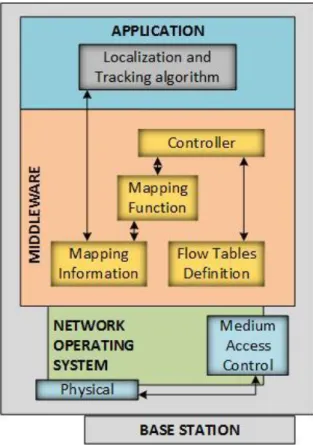
This extension is done by implementing the control-logic as part of the base station instead of having another entity that acts as a controller. In fact, the proposed architecture is an integration of a controller within the base station architecture and it consists of three layers: (i) Network Operating System (NOS) layer, (ii) Middleware layer, and (iii) Application layer. Figure 5 shows the base station architecture for this solution. The NOS layer works closely with the physical layer and the MAC layer of the base station, and its main function is to manage the access to the network and forward the packet according to its known rules. Since the functionality of NOS is similar to what we have already discussed in SDN, we will describe the middleware layer and the application layer in much more detail.
A Middleware layer
The Middleware Layer consists of a control logic called controller that creates flow rules based
on knowledge and information of the network topology. In order to get the required information the controller sends out a monitoring message, which requests for specific information such as energy level, distance to the base station (number of hops), neighbor list and status with each one (link quality, time from last connection, response time) and so on. These messages can be used by the controller for routing purposes. After gathering all the information, the controller starts defining the flow tables based on different aspects of the
Mapping Information (the information gathered from monitoring). The controller then sends
the forwarding information, which is related to each node in order to set their behavior. A copy of this information is stored in a database (called Flow Tables Definition) by the controller in order to be able to answer to requests from the sensor nodes (this is basically how routes
13
is saved in a route table). One thing to keep in mind is that each sensor node has its own flow table locally in order to reduce energy consumption by control traffic [24].
Flow Table Definition is a database component that stores different sensor nodes flow tables defined by the controller. A flow table consists of three different columns: (i) rules, (ii) actions and (iii) statistics. The rule describes the characteristics of packets that belongs to same flow. If the characteristic is meet then an action is executed, and finally statistics keep track of all packets that have satisfied the characteristics [24].
The Mapping Function is the component that processes the monitoring data received from the controller. This component has two main duties, one with the Mapping Information and one with the controller. First it maps the topology by taking every neighbor table sent by each sensor node in the network. This can be triggered via the controller either by a controller request (monitoring update) or by an application request (update request) [24]. The second is to give processed information (Mapping Information) to the controller.
The final component of the Middleware Layer is the Mapping Information component. Like the flow table definition, the Mapping information is a database that contain information about network interconnection between sensor nodes such as signal strength, link quality, reliability, and so on [24].
B Application layer
The Application Layer provides specific functionality (e.g. monitoring) in the WSN. In order to
perform its tasks, it uses information from the Middleware layer controller and Mapping Information components to ensure a proper interaction and monitoring is performed. But in order to use this information, the Application Layer is in need of the localization of the different nodes. This is why the Localization and Tracking Algorithms (LTA) component exist in the Application Layer [24].
LTA have the responsibility to collect and have accurate localization information. LTA have two duties: (i) using the Mapping Information in order to estimate the position of the node for the Application and (ii) creating an array for the position of the node in the Mapping Information. C Pros and cons of the solution
The main benefit of this architecture is the implementation of the control-logic into the base station, which brings down cost because another physical device for the controller is eliminated. This also gives a centralized controller directly without any implementation into the network. The way the controller is creating its view of the network gives the network mobility because of the controller sending out a monitoring message that is sent to all nodes in the network. These nodes then gives their neighbor list which can be updated whenever a new node in the network is added. This also means that new nodes can get this message and will be implemented in the controller’s view of the topology wherever it enters the WSN. It also provides simple network reconfiguration based on the SDSN architecture (see section 3.4.1).
14
The main drawback of this work is the lack of solid communication solution for using the interaction between the NOS and Middleware layer or Middleware and Application layer. It does not provide any specific solution for connecting the infrastructure to the controller. Moreover, like the previous descriptive paper, this paper provides some ideas that have not been implemented or tested. This work tackles three main issues, which are energy efficiency, mobility management and topology discovery. All of these problems seems to be solved in a great extent, the only one that may need more time to solve is the energy consumption problem, because of the above mentioned communication problems that have not been completely solved. Another thing to think about is that the base station need to be a little bit more powerful because of it becoming the controller of the network, this increases the cost. 3.4.3 Software-defined for clustered sensor networks
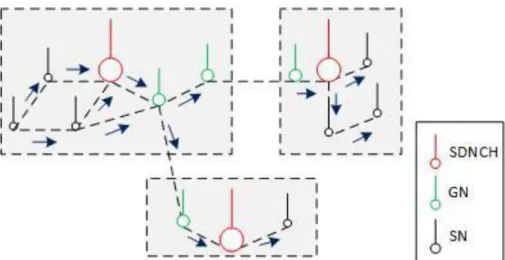
In this paper, the authors consider a WSN as a network that consist of hundreds or thousands of sensor nodes and, because of this is it important to organize them in an efficient way to get a better management and structure. One way for organizing the sensor nodes is by dividing them into different clusters. A cluster consist of a Simple Node (SN) which is a regular sensor node, a Gateway Node (GN) and a Cluster Head (CH) which is the base station of the cluster [25].
The authors use this idea and add SDN to it, and propose the Software Defined for Clustered
Sensor Networks (SDCSN) which is a structured SDN-based WSN solution for a network with a
big amount of sensor nodes. SDCSN makes it more efficient to manage the network operation by organizing the sensor nodes in different clusters (which is called an SDN domain). The CH in SDCSN is called an SDN Cluster Head (SDNCH) and takes care of all data in the SDN domain, it also sets the rules and policies in the SDN domain it is located in. This information can be shared with and sent to neighboring SDNCHs in the network. Each SDN domain works similarly to the solution given in section 3.4.2, there information gathered by the sensor nodes is sent to the base station (SDNCH). The difference is that there are more than one base station (SDNCHs) in the network (otherwise there is only one base station). The communication between the different SDNCHs goes via the GN in the SDN domain (see figure 6 for a view of this scenario). Another difference is that the SDNCH need to monitor and efficiently secure the domain from attackers. If a SDNCH goes down, the domain will be down temporarily until another sensor node takes over the role of a SDNCH. This gives the network load balancing and fault tolerance in the network [25].
15 A Interconnection between domains
The basic idea behind SDCSN is to build upon the SDSN architecture. This will be done by interconnecting all SDSN domains via border controllers (see figure 7). Every domain will have its own management, rules and security policies done by its SDNCH for each SDN domain in the network [25]. To strengthen each SDNCH in their SDN domains, will each SDNCH have a partial view of the entire network which will help them in communication exchanges between each other.
There are three different options to succeed in interconnecting the domains. (i) Equal
interaction, which gives all SDNCH a global view over the network. This information is
exchanged between the SDNCHs later. (ii) Master/Slave interaction where the SDNCH is the “slave” and sends information to the “master” controller in the network (the global controller). (iii) SDN Hierarchy, which is similar to the two other interconnections options. In SDN hierarchy does all sensor nodes in the domain send their information to the SDNCH, then it forwards this information to the global controller [25].
Figure 7 Domain Software-defined wireless sensor networks. Figure 6 communication between different SDN domains in the SDCSN.
16 B Pros and cons of the solution
The cluster solution gives a better management and structure of the network, which will make it easier with deployments of eventual new components into the network. For example can one of the clusters have one application specified for its SDN domain and another one is using a different type of monitoring application. This can make it easier to include a new sensor node in the network. The clustering at the same time solves the overlapping problem that can be created in WSNs. The new node can also be reprogrammed to match the application in the SDN domain it enters, because of it being built upon the SDSN architecture. It also makes it possible for sensor nodes to be more flexible when moving in network, this because of the different clusters checking their SDN domain similarly to how a regular base station does. Each SDN domain create their own topology view, which will lower the energy consumption for the global controller and the network. This process would otherwise have been done for the entire network. This topology view later is forwarded to the global controller which constructs a view over the entire network. With the fault tolerance in the network, is it possible for another SDNCH to take over whenever another neighboring SDNCH loses connection to the network. Which ease the management some further. Policies is handled by each SDN domain by their SDNCH with the information gathered from the sensor nodes in the SDN domain, which takes care of the policy problem in WSNs.
One of the problems that seems not to be detailed is how the SDN domain solves the problem of the GN loosing connection to the network. It mentions that the network goes down and no communication is possible from and to the effected SDN domain under this period. The fault tolerance regarding SDNCHS is solved, but nothing about when a GN loses connection have been described. This solution as previous two solutions mentioned before it, are not fully tested. Because of this we don’t really know if it will work or if it even will be possible for it to function as mentioned. Not much is mentioned on how the OpenFlow problems shall be fixed or anything about a substitution for the standard. One of the problems of the SDCSN solution is that every node in each domain seems to be a regular sensor node. Even the SDNCH which is supposed to take care of all information from the other sensor nodes and shall create a topology view over its SDN domain. Which later shall be forwarded to the networks global controller. This seems like a drawback because of the limited resources a sensor node have. The communication haven’t completely been mentioned on how it is going to be solved, a small mention about OpenFlow have been given, but as previously mentioned, it was not explained in detail.
3.4.4 SDN solution for wireless sensor networks
SDN WIreless SEnsor Network (SDN-WISE) [26] is a stateful SDN architecture solution for WSNs
that aims at (i) reducing the amount of information exchanged between sensor nodes and the SDN network controller, and (ii) making sensor nodes programmable as finite state machines. SDN-WISE answer many of the mentioned limitations when it comes to implementation of SDN in the WSN. To solve the energy limitation SDN-WISE supports duty cycle [27], which makes it possible to turn off the radio interface for a specified period of time and use this time
17
to perform data aggregation in the sensor nodes. States have implemented in the network which makes it possible to reduce the number of packet transmission in the network which reduces the energy consumption. Another limitation with implementation of SDN in WSN is the data-centric nature of them (which considers sensor’s data instead of their address ) [3, 26]. This have been solved in SDN-WISE by making it possible for controller to specify a rule for packets with different characteristics. In fact, it adds different classifications in the headers of the packets to create a flow. These classifications are for example: higher than, lower than,
different from, and etc. [26].
A The SDN-WISE approach
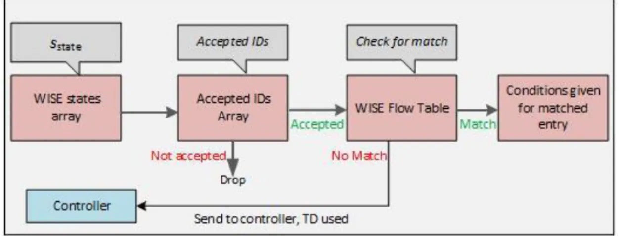
Everything done by the sensor nodes in SDN-WISE is based upon three data structures. (i) The
WISE states Array: as mentioned earlier, SDN-WISE considers different states to specify the
characteristics of the packets. The values of these states (which is a string of sstate) are saved in the WISE States Array. (ii) The Accepted IDs Array, which makes it possible for sensor nodes to only accept packets it must further process. This makes it possible for the sensor node to choose not to receive packets that are not specified for it. There is a field in the header of the packet which specifies an accepted ID of the packet. This packet is checked by the sensor node if it is part of the Accepted IDs Array, otherwise, the packet will be dropped. If the sensor node finds a match for the ID, it starts looking for a match rule in the WISE Flow Table. (iii) The WISE
Flow Table: which gives the conditions which should be applied to this packet. If no match is
found, then the sensor node sends a request to the controller for a new rule. For the sensor node to be able to perform this, it needs to have an entry in the table that gives the best next hop towards the controller. To find the next hop towards the sink, SDN-WISE performs a specified protocol called Topology Discovery (TD) [26]. See figure 8 to see an overall figure of what have been discussed.
.
18 B SDN-WISE protocol architecture
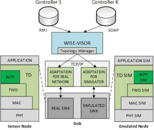
InIn the SDN-WISE network, sinks appear as the gateways between the data plane (sensor nodes) and the different elements which is implementing the control plane [26]. Figure 9 shows the Protocol stack of SDN-WISE implementation both on a real platform (the left hand side) and in the simulator (right hand side).
The protocol stack is divided into four layers. (i) The Forwarding Layer (FWD), which handles the packets that is arriving at the node according to the information given by the WISE Flow Table. The table is periodically updated by this layer whenever a configuration change is happening at the controller in the network. (ii) The In-Network Packet Processing (INPP) layer, INPP lies above the FWD layer, and is responsible for the in-network processing of data in the network. (iii) The Topology Discovery (TD) layer, which is the only layer that can access every layer in the stack in the means of appropriate Application programming Interface (API) and as can be seen in figure 9, is connected to every layer in the protocol stack. This makes it possible for the TD layer to gather local information and check the behavior of the nodes at every layer. TD also provide an API to the application layer. The APIs is managed by the Topology
Management (TM) layer which is part of the WISE-Visor controller in the control plane. The
TM layer makes it possible for different logical controllers with different policies can use the same set of physical devices in the network. TM uses the APIs which is offered by the different protocol layers, in order to make it possible for the different controllers to perform this operations. (iv) The application/adaptation layer, which lies between the WISE-Visor and the protocol stack. There is also an adaptation layer in the protocol stack with the same name, but they doesn’t do the exact same task. The task of the WISE-Visor Adaptation layer is to format
19
the messages sent from and to the WISE-Visor from the sink. The Adaptation layer in the protocol stack, is responsible for interacting with the simulated sink. This layer makes it possible for the control plane to set policies in a simulated network [26].
C Topology discovery
Topology Discovery (TD) is a protocol based on the exchange and processing of the appropriate
kind of packets called TD packets, and runs on all the sensor nodes in the network. The protocol is responsible for generating information about the topology from the node and forward this information to the WISE-Visor. The TD packets contain information about the node, such as battery level, Received Signal Strength Indication (RSSI) and the number of hops the node have to the nearest controller. This information is gathered by periodically broadcast a TD packet which is asking for information such as which hop is next towards the controller, its neighbors and etc. This is done in order to keep the view of the network up to date. At the same time the sensor node is getting the TD packet, does it clear its neighbor list. This is done because of the sensor node getting a fully updated list later from the controller. Whenever such a packet arrives at the sensor node, will it compare it to previous information it have acquired. This is done by the sensor node in order to see how the information differentiate from older information regarding the number of hops to the controller. This is also how the WISE nodes populates their neighbors list, which contains the neighboring nodes in the network [26]. The operations each node goes through when such a packet arrives is:
1. It inserts the node who sent the packet into the neighbors list with information about its battery level and RSSI. If the neighbor already exists then it will only update the information about the battery level and RSSI.
2. The sensor node will check if it have recently gotten a TD packet with a value that is lower than the current distance from the node to the sink. If this isn’t the case, then it will update the value and also set next hop to the controller to be equal to the node who sent the packet.
3. The sensor node updates the TD packet with its own battery level.
4. Finally it broadcast the packet with the updated information into the network. D WISE packet description
The SDN-WISE packet is a 10 bytes big packet that is divided into eighth different fields. These fields are (see figure 10 for a visual) [26]:
Packet length (7 bits), this field gives the size of the packet (payload) in bytes.
Scope (7 bits), this field is responsible to identify the controllers that is interested in the content of the packet.
Source and destination addresses (14 bits each).
U (0 bits), is a flag used to mark the packet which is in need to be sent to the nearest sink in the network.
Type of packet (7 bits), is a field used for distinguishing the type of message the packet is delivering from other packets. This will determine the packets payload in the end.
20 Time To Live (TTL), 7 bits
Next Hop ID (14 bits), this field is needed in the Accepted IDs Array in order for the packet to be further processed by the sensor node the packet is at.
E How packets is handled by the Forwarding Layer
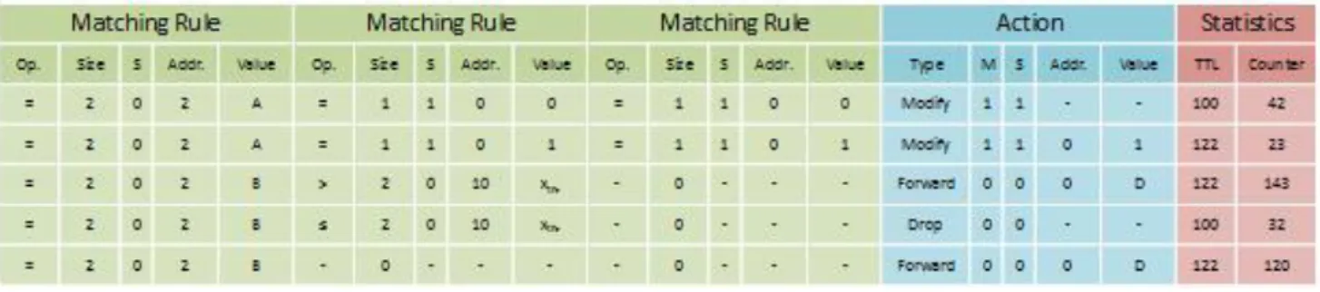
The WISE flow table consists of three different sections, similar to the flow table described in section 3.4.2-A. The flow table consists of (i) three rule fields, (ii) an Action field and (iii) a Statistics field (the statistics field will not be covered in this section because of it having exactly the same task as mentioned in section 3.4.2-A). The rules section in the flow table consists of three different conditions. If any of this conditions is matched, will an action be executed and the statistics section will be updated. Each matching rule consists of a field labeled S which specifies if the condition is regarding the current packet (labeled with a 0) or regarding the state (labeled with a 1). The matching rule also have a size field, which specifies the first byte and size of the string of bytes the packet or state have. The operator field, gives the operator (equal to, less than and etc.) that should be used to match the value field in the packet. If all of the sections is satisfying the rules, then the corresponding action to the rule will be executed, worth to mention is that if S=0, then the rule will not be considered. Figure 11 gives a representation of the WISE flow table.
An action is divided into five different fields. (i) The type field, which will specify which type of action will be executed. The actions that can be executed are: forward to, Drop, Modify, Send
to INPP, and Turn off radio. (ii) The M flag field which specifies if the entry is exclusive (M=0)
Figure 10 WISE packet header.
21
which is when the WISE flow table is only browsed once for the action, and not exclusive (M=1) which is when the WISE flow table will be continuously browsed and several actions can be used. (iii) The offset and (iv) value fields of the action is dependent on (v) the action field (the S field) and does different task depending on the action being used. The different tasks is dependent on these actions [26]:
If the action is “Forward to”, then these fields specifies the next hop ID which the packet will be updated with.
If the action is “Drop”, the probability of a drop is given and if the packet isn’t dropped, then it will do the same action as when the action is “Forward to”.
If the action is “Modify”, then it will specify the offset and a new Value that will be written. The S flag will also specify if the action shall be executed on the packet or the state.
If the action is “Send to INPP”, the processing type needed for this task will be specified.
If the action is “Turn off radio”, they will specify the time until the radio shall be turned on again.
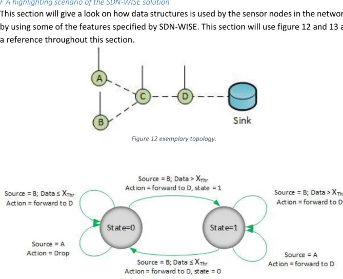
F A highlighting scenario of the SDN-WISE solution
This section will give a look on how data structures is used by the sensor nodes in the network by using some of the features specified by SDN-WISE. This section will use figure 12 and 13 as a reference throughout this section.
Figure 13 Finite state machine implementing a policy such that packets generated by are dropped if the last data measured by B is lower than Xthr.
22
First thing to think about is that everything measured by sensor node A is important only if it is lower than the data measured by sensor node B. This because of sensor node C dropping every packet that is lower than a threshold given by the value of xthr, which sensor node B have a higher value than. This cannot be accomplished by the OpenFlow standard because of two specific reasons, (i) it is not possible for the OpenFlow standard to check if the payload is “higher than” any specific value and (ii) because OpenFlow is stateless. Because of OpenFlows statelessness isn’t it possible to make a packet dependent on another packets content. This is possible to implement with the SDN-WISE flow table, were every rule must be satisfied and given the state of 1 which makes it possible to forward the packet to sensor node D. Otherwise it is given state 0 which is not considered at all in the SDN-WISE flow table [26].
This is specified in the five entries of the WISE flow table (see figure 11 for this part). The first entry selects packets that is coming from sensor node B. The second entry selects packets that have a higher value than xthr. The third entry is executed whenever a packet is generated in sensor node B and specifically specifies that the packet must be forwarded to sensor node D. The final two entries in the table specifies that packets that is arriving from sensor node A shall be dropped if the state is 0, or forwarded as previously mentioned to sensor node D if the state is 1 [26].
G Pros and cons of the solution
This solution is the first one that have been tested. This give a clarification that the solution actually is appropriate to use. SDN-WISE solve the majority of the limitations that will come with WSNs. To solve the energy limitations SDN-WISE uses the duty cycle approach, which makes it possible to turn off radio in the sensor node. Management becomes easier because of the introduction of states that makes it possible for the sensor nodes to make local decisions for simple tasks. This management part wouldn’t have been possible with OpenFlow which is stateless. SDN-WISE also have the possibility to manage traffic on all different layers in the network with the TD protocol. Policy changes becomes easier because of it being managed similarly to how a base station with a control logic implemented. The sensor nodes sends information to the controller which uses the information to create the rules and policies for the sensor nodes flow tables. This is also managed by the TD protocol. One of the things that stands out with SDN-WISE is that it allows the sensor nodes to only accept packets that is relevant to them. This is made possible by the Accepted IDs Array. This will reduce the energy used by each sensor, because the need to process packets that isn’t important for the sensor node will now not be necessary. The topology view of the network is being created in a similar way as in section 3.4.2. But with a small amount of differences. For example does SDN-WISE broadcast the localization packet via a broadcast channel, this isn’t done by the solution in section 3.4.2. The packet matches is done in a more advanced way that makes it more secure than previous flow tables. This is because of the WISE flow table having three different matches that the packets need to go through before an action can be used.
The only limitation that isn’t directly looked at is the TCP problem which is only given a small mention of being used in the WISE-visor when the solution were tested. It doesn’t mention
23
anything more on if TCP were used in SDN-WISE in general. Another problem not talked about is that all control messages is sent in-band of the network, instead of out-of-band. This could technically be solved by the ID array mentioned earlier.
24
4 SDN-Based Mobility solution
This section describes the proposed mobility solution for WSNs considering their intrinsic limitations. We first explain the proposed architecture, and then explain the details of the algorithm.
4.1 Architecture
Our proposed architecture will borrow and build upon some elements from each of the solutions described in section 3.4. In our proposed solution, we consider the cluster-based network architecture, which we refereed to each cluster as a domain. This strategy would provide scalability in networks with dense sensor nodes, while providing higher flexibility in network management. Each domain consists a number of sensor nodes, where each node would service multiple applications (for example environmental monitoring and health monitoring) that measure the required information, and collect the information received from neighbor nodes.
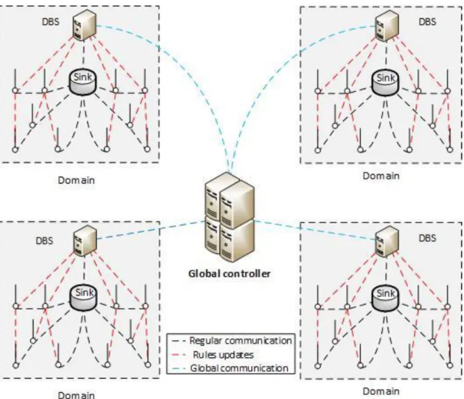
The architecture consists of a more powerful sensor node that is called sink node. The sink node collects all the information from the sensor nodes in the domain and forwards to the base station, which includes a control logic. These two nodes (sink and base station) are stronger in order to manage the network and handle all the control packets generated in the network. The base station, which is called Domain Base Station (DBS) serves as a local controller in the network and sends rules to sensor nodes to implement their flow tables. Sensor nodes will follow the rules introduced by the local controller for forwarding the traffic. When the DBS receives all the information from sensor nodes, it creates the network topology and issues rules accordingly. DBS sends a copy of the network topology to the global controller. This way, the Global controller have the global view of the network and can make better decision in case a local controller fails to do so. Thus, during the run-time all the domains within the sensor network are able to request the global controller to update their rules. Adding the local controller reduces the signaling load from the infrastructure to the global controller layer. In case either the sink or the DBS would lose connection to the network, it would be possible for the global controller to temporary take over the DBSs responsibilities. This makes it possible for the sensor nodes to continue with their monitoring until the DBS is back up. See figure 14 for a view of the architecture.
25 4.2 The mobility approach
This section first gives an overall picture on the processes that will be used in the network in order to proceed when a mobile node is entering the WSN. Then we will provide more details related to the mobile nodes, the stationary nodes and the DBSs.
4.2.1 Intra domain mobility solution
Below, we define a number of steps that are used for handling mobility between different stationary nodes in a single domain:
1. Initially, mobile node is connected to one of the stationary nodes. Mobile node sends data periodically to the static nodes. Thus, the stationary node keep track of RSSI variations. See figure 15.
Figure 14 Proposed architecture, consisting of one global controller, and several domains with one DBS and sink each.
26
2. If the RSSI values at the static node degrades to a threshold level (RSSI<TH1), then it sends a beacon to the DBS “remove request” in order to detach the mobile node. However, the DBS keeps the connection until receiving a request from another static node with high link quality. See figure 16.
3. If a neighbor static node within the same domain receives beacons from the mobile node, and it detects that the RSSI value, related to the orphan mobile node is higher than a threshold (RSSI>TH2, where TH2>TH1), and the RSSI values are growing (slopeRSSI>0), then the stationary node sends a “join request” to the local controller. See figure 17.
Figure 15 mobile node (red circle) periodically sends data to the static node.
27
4. When DBS receives a “join request” from a static node, it starts a timer (join timer) with short period to make sure that there are no other “join requests” from other static nodes.
5. After expiring the join timer, the DBS sends the rules to the requested static node with high link quality in order to update the flow entry and accept joining the mobile node. In case where there are more than one stationary node sending same join request, the DBS sends the rule to the static node with the highest RSSI value. See figure 18.
4.2.2 Inter domain mobility solution
Below, we define a number of steps that are used for handling mobility between different domains:
1. Initially, an orphan mobile node periodically broadcasts beacons that has the “integration request” in order to join one of the existing domains. See figure 19.
Figure 17 neighbor static node receive beacons and sends "join request" (green line) to DBS.
28
2. When a stationary node receives the “integration request”, it starts tracking the change in the RSSI value, related to the orphan mobile node. If the RSSI values are higher than a threshold (RSSI>TH2, where TH2>TH1), and the RSSI values are growing (slopeRSSI>0), then the stationary node sends a “join request” to the local controller, which is then sent to the global controller. See figure 20.
Figure 19 mobile node (red circle) broadcasting integration requests to nearby domains.
Figure 20 stationary nodes sends "join request" (green line) to local controller, which is then sent to the global controller.
29
3. When global controller receives a “join request” from a local controller, it starts a timer (join timer) with short period to make sure that there are no other “join requests” from other local controllers. This case may happen if the mobile node is moving at the very edge of two neighbor domains.
4. After expiring the join timer, the global controller sends the rules to the requested local controller in order to update the flow entry of its stationary node. In case where there are more than one local controller sending same join request, the global controller send the rule to the controller with the highest RSSI value. See figure 21. 5. Global controller sends a message “ignore request” to the local controller(s) with lower
RSSI value in order to ignore requests from that specific mobile nodes. Then stationary nodes that receives requests from the mobile node, start a timer “ignore timer” with a specific period. The reason is that the mobile node may change its trajectory, and get closer to the current domain. Thus, the “ignore request” is valid for a certain period of time. See figure 21.
4.2.3 Mobile sensor node mobility algorithm
An orphan mobile sensor node broadcasts “integration requests” to nearby stationary sensor nodes until it receives a reply from a stationary node.
4.2.4 Stationary sensor node mobility algorithm
Upon receiving an “integration request”, the stationary node checks its RSSI value. If RSSI > TH2, stationary node sends a “join request” to the DBS in its domain. If the DBS replies with sending rules, stationary node will start adapting the rules for mobile sensor node. It might happen that the DBS, receives a join request from other stationary nodes, and found that stationary node to be the best candidate for the mobile node. In this case, the DBS will send an “ignore request” message to the stationary node. If the DBS replies with “ignore request”,
Figure 21 global controller sends rules (blue line) to controller with higher RSSI and "ignore request" (red line) to controller with lower RSSI.
30
stationary node will ignore “integration requests” for a specified time. When the timers have expired, then the process will be able to begin again. See figure 22.
4.2.5 Domain base station mobility algorithm
This algorithm is for a DBS when receiving any type of request from stationary sensor nodes. Upon reception of “remove request”, if no “join request” have been received by another stationary sensor node, the DBS wait until such a request have been received. If a “join request” have been received, a timer start in case more “join requests” will be sent by other stationary sensor nodes. If only one “join request” is received, then the DBS send rules to the sensor node sending the “join request”. If other stationary sensor nodes sends a “join requests”, then the DBS compare the RSSI values of each of the nodes sending “join requests”. The node with a lower RSSI value will receive the “ignore requests” and the node with a higher RSSI value will be given new rules. Same procedure will happen in a higher level, between the DBS and the global controller if a mobile node is traversing between the domains. If an “integration request” is received, the DBS sends a “join request” to global controller. If the global controller replies with a “ignore request”, the DBS will ignore data received from the mobile sensor node for a specified time. If the global controller replies with a rule, the DBS adapt the rule(s) to the stationary sensor node. See figure 23.
31 4.2.6 Global controller mobility algorithm
This algorithm is for the global controller after receiving join request from DBSs. Upon receiving a “join request”, the global controller starts a timer and waits for more “join requests”. If timer expires and no other “join requests” have been received, then it sends rules to the DBS that sent the “join request”. If other “join requests” is received, the global controller compare RSSI values reported from DBSs. The DBS with a stationary node that has higher RSSI value will receive rules and the DBS with stationary node that has lower RSSI value will receive an “ignore request”. See figure 24.
32