Cab Door Design
-
Improvement of door corners
Thesis Work
15 Credits, Basic Level
Product Development – Mechanical Design Process
Product and Process Development
Course code: KPP301
Akib Biswas Islam
Commissioned by: Volvo Construction Equipment Tutor (company): Robert Sundkvist, Leif Norling Tutor (university): Bengt Gustafsson
Examiner: Marcus Bjelkemyr
i
Cab Door Design
ABSTRACT
This thesis presents a product development process, where an existing solution on a cab door have been analysed and developed, with the aim to result in a cost-effective concept solution for handling tolerances on the door frame. The methodological approach in this thesis is based on Volvo Construction Equipment’s development model; The Global Development Process, which started with a pre-study phase where the problem formulation was established.
The problem formulation in short is to find a solution for how to handle narrow tolerances in steel profiles for the door weldment on cab doors. Various solution ideas were discussed and concepts were generated with focus to design a new cab door corner that would solve the problems addressed by the project.
The applied method resulted in a final concept consisting of the same steel profiles but with new dimensions, and two new concepts in each corner; one corner module that is placed inside the steel profiles and joined by welding, and a plastic shell that covers the welded corner.
The concept was validated using a prototype of the proposed solution, where tests show that the requirements were achieved, besides a few deficiencies.
A cost comparison between the existing and the proposed solution was made within limitations for this thesis. The result of the cost comparison shows an indication of that the proposed solution can be more cost-effective than the existing solution.
Some of the recommendations after have completing the project are to make a complete cost comparison to ensure that the indication is correct and to analyse the new components to optimize and define the dimensions of them.
INFO
Thesis Work, 15 Credits Basic level
Author:
Akib Biswas Islam Commissioned by:
Volvo Construction Equipment Tutor:
Bengt Gustafsson, Mälardalen University
Robert Sundkvist, Volvo CE Leif Norling, Volvo CE Examiner:
Marcus Bjelkemyr, Mälardalen University
Presentation date: June 13th 2014
Keywords:
Cab door corner, steel profile, welding, product development,
cab door, design, tolerances.
ii
ACKNOWLEDGEMENTS
I would like to express my appreciation to all the people who gave me the possibility to complete this thesis.
First of all I would like to thank Robert Sundkvist, Manager for Cab & Operators Environment at Volvo CE, for initiating the thesis work and giving me the opportunity to work with it.
I also wish to thank…
My supervisor at Mälardalen University, Bengt Gustafsson, for providing me with valuable guidance and feedback from day one, for reading and commenting on the report and for being a great sounding board as well as helping me taking decisions in critical moments.
Leif Norling, supervisor at Volvo CE, for supporting me and pushing me in every situation as well as for helping me to understand the complexity in this thesis and keeping my focus straight.
Andreas Korff, welding engineer at Volvo CE, for introduced the production line for cabs and cab doors in Hallsberg cab factory as well as providing me with resources to build and test the prototype.
Ulf Rehn, project buyer at Volvo CE, for providing me with financial documents and cost allocations to base my calculations on.
I would also like to thank all other employees at the department for Cab & Operators Environment at Volvo CE for receiving me with a warm welcome and for providing me with help, information and opinions throughout the whole project.
Finally I would like to thank my family for always supporting me and encouraging me to do my best in all situations.
Eskilstuna May 30th, 2014 Akib Biswas Islam
iii
CONTENT
ABSTRACT ... i
INFO ... i
ACKNOWLEDGEMENTS ... ii
LIST OF FIGURES & TABLES ... v
ABBREVIATIONS ... vi
1. INTRODUCTION ... 1
1.1. Background ... 1
1.2. Project Directives ... 2
1.3. Problem Formulation ... 2
1.4. Aim and Research Questions ... 2
1.5. Project Limitations ... 3
2. METHODOLOGY & THEORETICAL FRAMEWORK ... 4
2.1. Methodology ... 4
2.1.1. Pre-Study ... 5
2.1.2. Concept Study ... 6
2.1.3 Detailed Development ... 7
2.1.4 Final Development ... 8
2.2. RPS - Reference Point System ... 8
2.3. Tolerances ... 9
3. APPLIED METHODOLOGY ... 10
3.1. Pre-Study ... 10
3.2. Concept Study ... 13
3.2.1. Product Specification ... 13
3.2.2. Functional Analysis on project solution ... 14
3.2.3. Functional Analysis on cab door corner... 14
3.2.4. Idea Generation ... 15 3.2.5. Concept Generation ... 15 3.2.6. Concept Selection... 18 3.3. Detailed Development ... 19 3.3.1. SWOT Analysis ... 19 3.3.2. Concept Development ... 19 3.4. Final Development ... 20 3.4.1. Prototyping ... 20
3.4.2 Design for Manufacturing ... 20
4. RESULT ... 23
iv
4.1.1. Components and Material ... 24
4.1.2. Assembly ... 25
4.2. Testing and Validation ... 26
4.2.1. Test Results ... 26
4.3. Cost Comparison ... 27
4.3.1. Estimated prices on production times ... 27
4.3.2. Estimated prices on new components ... 27
4.3.3. Cost comparison on steel profiles ... 27
4.3.4. Summery and Conclusions ... 28
5. ANALYSIS & DISCUSSION ... 29
5.1. Aim and Research Questions ... 29
5.2. Achieved Functions ... 30
5.3. Discussion ... 32
5.3.1. Analysis ... 32
5.3.2. Cost Comparison ... 33
6. CONCLUSIONS AND RECOMMENDATIONS ... 34
6.1. Reflections and summary of the thesis work ... 34
6.2. Conclusions ... 34
6.3. Recommendations ... 35
7. REFERENCES ... 36
8. APPENDICES ... 37
APPENDICES
Appendix 1 – Gantt chart
Appendix 2 – Preferred steel profile
Appendix 3 – Pictures of steel profiles used in Idea Generation Appendix 4 – SWOT Analysis
Appendix 5 – Concept Development Appendix 6 – Prototyping
Appendix 7 – Prototype testing Appendix 8 - Concept drawings
v
LIST OF FIGURES & TABLES
Figure 1: Cab door for wheel loaders. ... 1
Figure 2: Section view of the steel profile ... 1
Figure 3: The phases in The Global Development Process ... 4
Figure 4: The four first phases in the GDP. ... 5
Figure 5: Example of a time plan in a Gantt chart. ... 5
Figure 6: Concept selection through the process. ... 7
Figure 7: SWOT-matrix ... 7
Figure 8: Steel profiles in fixture for door frame. ... 10
Figure 9: Gaps between steel profiles ... 11
Figure 10: Reinforcement using pliers ... 11
Figure 11: Sketch of idea 1 and 2... 15
Figure 12: Idea 1, Concept 1 ... 16
Figure 13: Idea 1, Concept 2 ... 16
Figure 14: Idea 2, Concept 1 ... 16
Figure 15: Idea 2, Concept 2 ... 17
Figure 16: Idea 2, Concept 3 ... 17
Figure 17: Idea 2, Concept 4 ... 17
Figure 18: The physical models used for concept development. ... 19
Figure 19: Visualisation of the amount material that can be saved. ... 21
Figure 20: Visualisation of total scrap material in both solutions ... 21
Figure 21: Visualisation of the both cutting surfaces... 22
Figure 22: Final concept applied on a door frame. ... 23
Figure 23: Corner Module. ... 24
Figure 24: Plastic Shell. ... 24
Figure 25: Steel profile... 25
Figure 26: The leakage from prototype tests... 32
Table 1: Pugh's matrix ... 18
vi
ABBREVIATIONS
CAD - Computer Aided Design
CAST - Common Architecture Shared Technology
DFM - Design for Manufacturing
GDP - Global Development System
RPS - Reference Point System
1
1. INTRODUCTION
1.1. Background
This report presents a thesis work on basic level, commissioned by Volvo Construction Equipment (Volvo CE) in Eskilstuna during the course KPP301 at Mälardalen University, Sweden.
Volvo CE develops, manufactures and markets construction equipment such as wheel loaders, backhoe loaders and dumpers. Some of the cabs of these machines are constructed in Eskilstuna and are manufactured in Hallsberg.
The cab doors (Figure 1) consists of steel profile tubes (Figure 2) which are manufactured by a subcontractor. These steel profile tubes are cut to the right angle and length within narrow tolerances, before delivery to Hallsberg, where they get welded in the corners to create the door frame.
This thesis work was initiated by Volvo CE to investigate the existing steel profiles and the door production with the goal to find a solution to handle the narrow tolerances on the door frame.
Figure 1: Cab door for wheel loaders. Figure 2: Section view of the steel profile The section view is confidential.
2
1.2. Project Directives
Volvo CE has difficulties to handle tolerances in steel profiles for door weldment in the Hallsberg cab factory. These narrow tolerances make the production more time consuming and expensive than necessary.
Volvo CE wants to find a solution for handling narrow tolerances by handing out this mission in a thesis work with the following main activities:
Analyse and understand the magnitude of the tolerance problem in door weldment in Hallsberg cab factory.
Design a solution that handles wider tolerances to use in both new and existing door production.
Validate and test the proposed solution in theory and practice.
Make cost comparisons between existing and proposed solution.
1.3. Problem Formulation
The project in short is to find and develop a solution for how to handle narrow tolerances in steel profiles for the door weldment on wheel loader doors, by using a relevant product development process.
1.4. Aim and Research Questions
The aim of this project is to identify the magnitude of the tolerance problem in door weldment for a wheel loader door, and to find a cost-effective concept solution for handling these problems. The concept should be developed to fulfil all the necessary functions and contain an attractive design. The goal is to manufacture a prototype of the concept which will be used to validate how the concept fulfils the requirements and the result will be documented in this report.
Research questions:
1. How, when and where does the tolerance problem occur? 2. Which costs can be reduced by increasing tolerances? 3. Will the proposed solution be more cost-effective?
3
1.5. Project Limitations
This thesis work in course KPP301 is on basic level and covers 15 credits on full time, which corresponds to 40 hours a week for ten weeks during the spring semester 2014. The project was executed from the 31th of Mars to the presentation on 12th of June. The final report is to be submitted 2 weeks before presentation day. A priority order and certain limitations have been established due to time limits, scope of directives and aim of the project.
Since this thesis focuses on the product development and mechanical design process, the first two main activities will be in high priority. These will result in a well-developed concept as a proposed solution. Next step is to validate and test the proposed solution in theory and practice, which requires a prototype based on the final concept. Cost comparisons will be made during the whole process, but these will be limited due to time limitation and scope of this thesis.
Limitations:
The solution is to be kept on a concept level.
CAD models and drawings only need to have the most crucial dimensions since the optimal dimensions will not be defined.
The cost comparisons will be made within the limitations of: - Material costs for steel profiles.
- Processing costs on steel profiles, including cutting phase only. - Prices on new components.
- Costs for assembly the door frame. - Investments in new tools.
4
2. METHODOLOGY & THEORETICAL FRAMEWORK
2.1. Methodology
The methodological approach in this thesis is based on Volvo CE’s development model – The Global Development Process (GDP) (GDP booklet, 2007; GDP Pocket Guide, 2011), complemented with methods from The Mechanical Design Process (Ullman, 2010) and The Product Development Process (Ulrich & Eppinger, 2012). This chapter will first describe the GDP and the relevant phases of it and then describe the methods that have been implemented to the various phases of the Global Development Process.
The GDP is used as reference point in the product development process and in the execution of a project for the profitability of Volvo CE. The GDP is divided into six phases: Pre-Study, Concept Study, Detailed Development, Final Development, Industrialization and commercial-ization, and ends with a follow up (Figure 3).
Figure 3: The phases in The Global Development Process (Volvo Group
http://reports.volvogroup.com/en/EnvironmentalResponsibility/ProductDevelopment.html) The purpose of the GDP is to ensure customer satisfaction and competitiveness in the market by defining guidelines for an effective product development and the ability to execute projects in a structured way, which is critical to success. To follow the GDP structure is the basis as well as the minimum requirement for product development at Volvo CE. (GDP booklet 2007, p. 4)
This thesis focuses mainly on the three first phases of the GDP (Figure 4): Pre-Study, Concept Study and Detailed Development. Depending on the time consumption of the three first phases, the project can continue to the fourth phase: Final Development. These four phases are complemented with methods from The Mechanical Design Process (Ullman, 2010) and The Product Development Process (Ulrich & Eppinger, 2012).
5 Figure 4: The four first phases in the GDP.
Every phase of the GDP will be completed with at least one scientific method and these methods will be described below. The combination of methods in the different phases will together represent the complete process used in this thesis.
2.1.1. Pre-Study
The Pre-study phase is about defining the scope of the project by establishing project conditions such as goals, directives, limitations and problem formulation (GDP booklet 2007, p. 14; GDP Pocket Guide 2011, p. 8). The pre-study phase includes methods for Project planning and Product definition.
Project Planning
The project started with directives to “Find a solution for joining of cab door
corners with profiles” from Volvo CE as input. The first step is to establish a project
plan, tentatively with a Gantt chart1 (Appendix 1). The Gantt chart shows a time plan for the entire project, including all phases, with starts and ends.
The output of the planning phase is the mission statement (Ulrich & Eppinger, 2012). A well-defined mission statement will give a realistic time plan (Figure 5).
Figure 5: Example of a time plan in a Gantt chart.
6
Product Definition
During the product definition phase, the goal is to understand the problem, establish a problem formulation and define the conditions and limitations of the project. Ullman (2010: p. 143) states that “Understanding the design problem means to
translate customers’ requirements into a technical description of what needs to be designed.” Volvo CE is the customer in this case, and their requirements are partly
defined in the project directives. A current situation analysis must be done to collect and understand all customer requirements and needs.
Five-step method for identifying customer needs (Ulrich & Eppinger, 2012, p. 75) 1. Gather raw data from customers.
2. Interpret the raw data in terms of customer needs.
3. Organize the needs into hierarchy of primary and secondary needs. 4. Establish the relative importance of the needs.
5. Reflect on the results and the process.
2.1.2. Concept Study
This phase is about understanding the problem and analyses alternative concepts, where one of the concepts will be selected for development (GDP booklet 2007, P. 16; GDP Pocket Guide 2011, p. 8). The Concept Study phase includes establishing a product specification as well as methods for concept generation and concept selection.
Product Specification
Specifications should be established early in the process and then proceed to design and engineer the result to meet those specifications (Ulrich & Eppinger, 2012, p. 93). In this case there is a manual to follow for how doors should be constructed. Most of the specifications are defined in the manual: CAST For Doors - Preferred
solutions, these will be completed with new specifications to match the customer
requirements.
Concept Generation
Use the understanding of the problem and the specifications as a basis for generating concepts in this phase. “Form follows function. Thus we must first
understand the function of a device, before we design it” (Ullman, 2010, p. 171).
The function will be based on customer needs and product specifications, and then concepts will be generated to meet the function. The key point of a concept is that enough details must be developed to ensure the functionality of the idea.
A Functional Analysis can be useful to do before the concept generation, where the main function, sub-functions and additional functions will be defined.
7
Concept Selection
Concept selection is a repeated process (Figure 6) through the development process from concept study to final result, closely related to concept generation and concept testing. Start with the concepts from the earlier phase; screen out the concepts using Pugh’s matrix (Ulrich & Eppinger, 2012, p. 150). Generate new concepts, combine qualities and develop concepts further, then repeat the concept selection.
Figure 6: Concept selection through the process (Ulrich & Eppinger, 2012, p. 148).
2.1.3 Detailed Development
In this phase the focus is to start developing components/parts based on the specifications produced in the earlier phases and defining the solutions to be implemented. At the freeze gate in the middle of this phase all solutions should be approved and all requirements on components/parts should be frozen. (GDP booklet 2007, p. 18; GDP Pocket Guide 2011, p. 8) SWOT-analysis and Concept development will be made during this phase.
SWOT analysis
SWOT stands for strengths, weaknesses, opportunities and threats. SWOT analysis is a common method which will be conducted on concept that is left to this phase. The method is based on a quad chart where each of four quadrants filled in with SWOT entries (Figure 7). SWOT analysis makes it easier to judge a concept and detect qualities that have to be improved.
Concept Development
Improve the weaknesses and combine the strengths to implement them together in one concept. Strive to optimize the opportunities and eliminate the threats. Develop components and define dimensions for the final concept. Make a digital 3D-model, drawings and a mock-up of the result.
Figure 1: SWOT-matrix Figure 7: SWOT-matrix
8
2.1.4 Final Development
The Final Development phase in this project will focus on building, verifying, validate and refine the product solution. This phase will also focus on defining manufacturing and assembly solutions. (GDP booklet 2007, p. 20; GDP Pocket Guide 2011, p. 9)
Prototyping
A prototype is defined as “an approximation of the product along one or more
dimensions of interest.” (Ulrich & Eppinger, 2012, p. 290). Prototypes can be
classified along two dimensions: the physical dimension and the comprehensive. A physical prototype are tangible subjects manufactured to approximate the product while a comprehensive prototype implements most, or all attributes of the product. This concept will be tested in a physical prototype while the digital 3D-model will correspond to the comprehensive prototype.
The prototype will be used to answer two questions: “Will it work?” And “How
well does it meet the customer needs?” (Ulrich & Eppinger, 2012, p. 294). Manufacturing
Design for Manufacturing (DFM) is a method used to “establish the shape of
components to allow for efficient, high-quality manufacture” (Ullman, 2010, p.
328) and consists of five steps (Ulrich & Eppinger, 2012, p. 256): 1. Estimate the manufacturing costs.
2. Reduce the costs for components. 3. Reduce the costs for assembly.
4. Reduce the costs of supporting production.
5. Consider the impact of DFM decisions on other factors.
2.2. RPS - Reference Point System
This section will describe the Reference Point System which is a system used in production of all parts in a machine, and is relevant in this thesis due to the fixture that is used in door weldment.
A reference point is a point used in the design and production to assure quality in a part expressed with values in a 3-dimensional system. Each point has three coordinate values, X, Y and Z in this system.
The Reference Point System (RPS) is a way to control all aspects of a 3D geometry, where the Reference Points are the link from CAD model to physical part (RPS handbook, 2011).
9
2.3. Tolerances
Tolerances are one of the key terms in this thesis and will be described to ease the reading and understanding of the tolerance problem.
Tolerances are the acceptable variations on the value for a specific unit, the allowed values for a specific length dimension for example. A tolerance can also be the requirement on a shape, as straightness and flatness.
It is impossible to measure the exact dimension. There will always be a more accurately measuring instrument that shows a further decimal, and that is why tolerances are necessary. (Taavola, 2009, p. 116)
A narrow tolerance often implies high processing costs and long setup times since the manufacturing of a part with narrow tolerances has to be precise.
A wider tolerance implies a less accurate process, which often results in a faster and cheaper manufacturing. But wider tolerances could lead to consequences as gaps between parts and fitting problems.
10
3. APPLIED METHODOLOGY
Following chapter explains how the methodology is performed and presents the empirical results from the pre-study and concept study, which the concept development and the final result will be based on.
3.1. Pre-Study
The Pre-study phase was focused on identifying customer needs and this was made by gathering raw data from the customer, interpret the raw data in terms of customer needs and finally organize the needs into hierarchy of primary and secondary needs. Raw data in form of Requirement Specifications, CAST for cabs handbook, RPS handbook, CAST for doors and Cab Frame Design Guidelines was collected and analysed to help understand the manufacturing of cabs and doors.
A study of the manufacturing in Hallsberg cab factory was made to complement the gathered data of the manufacturing process. The study was made on the whole cab but focused on door welding and contained observations of both wheel loader and backhoe loader doors to get a wider point of view.
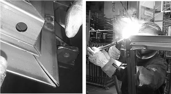
The wheel loader door frame consists of five steel profiles tubes with different lengths and angles for every part of the door frame, which get loaded in a fixture (Figure 8) with RPS by the welder. The steel profiles gets loaded in a certain order, where the part with the narrowest tolerances is the first part placed in the fixture and the last of the five parts to be placed is the one with widest tolerances, which has a purpose to complete the missing tolerances for the door frame.
Steel profile tubes are joined together by welding one corner at a time in the fixture. The welder takes the joined door frame and puts it in a welding robot which does the final weldment.
If the steel profiles are not properly joined with each other, the welding robot can burn through the material, which has to be reinforced and adjusted by hand afterwards.
11 A not properly joined door frame is a consequence that occurs when the required tolerances on steel profiles not have been achieved, which can depend on various factors:
The steel profiles are manufactured as six meters long tubes, by a subcontractor, who cut them off with correct angle and length for every article of the door frame. The length and angles of the steel profile tubes must be precise, which requires narrow tolerances in the cutting phase. The tube consists of a longitudinal weld through the whole tube, which can conduct to heat deformations with the consequence of cutting the steel profiles are made outside the required tolerance. The fixture are built to handle tolerances in a way where the part with the narrowest tolerances is placed first and the remaining parts are placed with the end of the previous part as a reference point in the RPS. The fixture are not adjusted for the different parts with different tolerances and the tolerances problem is an effect of the reference point in the end of each part, where the latest added part are depending on the tolerances from previous part.
Despite the required tolerances and the use of RPS in the fixture, there are some gaps that can occur between the steel profiles (Figure 9).
The gaps have to be adjusted and reinforced before the door gets placed in the welding robot. These adjustments are made by hand which extends the production time. If the gaps are too big, the welder needs to use pliers to force the edges together (Figure 10) during the reinforcement. These are some of the big problems with tolerances in door weldment, especially in backhoe loader doors.
12 2. By studying and observing the door manufacture and analysing raw data, it was possible to understand the problems and interpret data from the study to customer needs.
Interpreted needs:
Preclude gaps between profiles.
Reduce the manual adjustments.
Reduce scrap material.
Wider tolerances for cutting of steel profiles.
3. Some of the needs depend on each other, and are therefore hard to organize in hierarchy. If it is possible to remove the gaps between profiles, the effect could lead to reduced manual adjustments, for example.
Wider tolerances when cutting could increase gaps between profiles, but it would reduce the production time significantly if the solution handles both problems. Wider tolerances could also reduce scrap material.
Primary need:
Wider tolerances for cutting of steel profiles.
Preclude gaps between profiles. Secondary need:
Reduce the manual adjustments.
13
3.2. Concept Study
The concept study phase was focused to establish a well-analysed base to develop and build the concept solution on. This was made by defining specifications for the product and by analysing and identifying necessary functions that the solution must fulfil. An idea and concept generation was performed with the functional analysis as basis. The concept study phase ended with selecting some of the generated concepts using a selection matrix to develop further.
3.2.1. Product Specification
A product specification for the door was established based on customer needs, project limitations, directives and Volvo CE’s internal document: CAST For Doors
- Preferred solutions.
Profile: Preferred steel profile shall be according to drawing on appendix 2.
Welding: Robot welding should be preferred when designing the door frame. If possible: design the door frame so that no gaps will occur and minimize the manual adjustments. Door sealing: The door sealing has the shape of a bubble that shall
correspond with the meeting surface. The sealing bubble has to remain on the flat surface to prevent poor fitness and leakage.
Reference Point System: If the solution requires a change in the use of Reference Point System, find an equal system that can be applied and prove that the system will gain time.
Hinges and Hand rail: The solution for door corners may affect hinges and hand rails, but it has to adapt to fit the existing requirements for these parts.
Specifications for locking system, window, panels and product identity are written in CAST for doors – Preferred solutions and will not be mentioned in this thesis because it is classified as confidential. The solution is focused on cab door corners and will therefore not affect the existing specifications.
14
3.2.2. Functional Analysis on project solution
A functional analysis was made on the project solution to define the functions and sub-functions that the solution shall fulfil. These will then be the base for the idea generation.
Main function: Joining of cab door corners.
Sub-functions: Preclude gaps between steel profiles. Increase tolerances on steel profiles. Reduce scrap material in manufacturing. Reduce the manual adjustments.
Additional functions: Make the solution more cost-effective.
3.2.3. Functional Analysis on cab door corner
The main function of the functional analysis on the project solution is joining of cab door corners with sub functions that could be solved by designing a new door corner that fulfils the identified functions.
The solution should therefore contain a new cab door corner that fulfils the functions in earlier functional analysis. A new analysis was done at the cab door corner, to identify which functions the existing door corner fulfils and which functions the new corner must fulfil.
Main function: Joining of cab door frame. Sub-functions: Fix the door sealing strip.
Keep tight between door and doorway.
Prestressed corner, so the top corner is the first part to connect with the doorway.
Additional functions: Robot welding is preferred.
15
3.2.4. Idea Generation
Idea generation phase started with a short brainstorming where alternative solution ideas on a cab door corner were generated. These ideas were given as starting point for the concept generation. The three following solution ideas are the result of this phase:
1. Find a solution on a door with same steel profile, lengths and angled cuts as the existing door.
2. Find a solution on a door with same steel profile, but new lengths and perpendicular cuts against the long side.
3. Design a new steel profile with new lengths and new angled cuts. Concepts should be generated on all three ideas, but because of the time limitations and the project scope, no concepts will be developed on idea 3. To design a whole new steel profile that handles the tolerance problem and still have all the functions as the existing door is too extensive and time consuming for this thesis.
3.2.5. Concept Generation
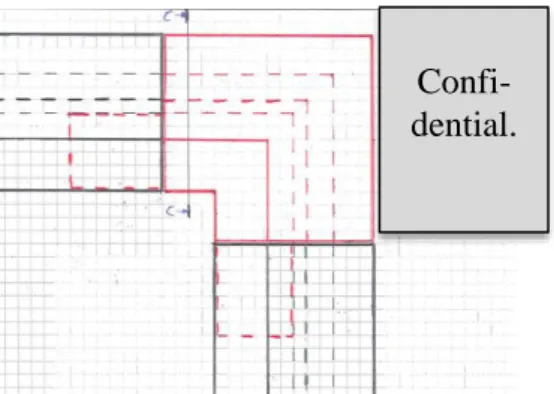
Idea 1 and 2 was visualised with two steel profiles (appendix 3) and sketched to easier understand the ideas. The sketches (Figure 11) were used to generate concepts. Idea 1 is to the left, idea 2 in the middle and a section view of the existing steel profile to the right. These, combined with the product specifications and result from the functional analysis, are the input components for the solution to handle.
Figure 11: Sketch of idea 1 and 2.
The section view is confidential.
16 Concept 1.1 – a square tube with the correct
angle for each corner that gets placed inside the existing cab door corner. The square tube has dimensions to fit the inside of the steel profile which will help to fix the tolerances in the corners (Figure 12).
Manufacturing: Moulding in plastic.
Concept 1.2 – similar to Concept 1.1 but with a rib to fill the whole empty space on the inside of the steel profile. The rib should help to handle gaps on the tip of the corners (Figure 13).
Manufacturing: Moulding in plastic.
Concept 2.1 – the steel profiles will have perpendicular cuts and be joined by the same square tube as in Concept 1.1. This will change the look of the corner and the door will not have any corner tip. The perpendicular cuts against the long side reduces the scrap material in the cutting phase and will give wider tolerances that squere tube on the inside should be able to compensate for. (Figure 14).
Manufacturing: Moulding in plastic and glue the steel profiles together with the module. Moulding in steel and weld the steel profiles together with the module.
Figure 12: Idea 1, Concept 1
Figure 13: Idea 1, Concept 2
17 Concept 2.2 – a rounded corner with the same
section view as the steel profiles. The module contains square tubes at both ends that will slide in to the steel profiles and join the door frame as well as fix the flange for door sealing (Figure 15).
Manufacturing: Moulding in plastic and glue the steel profiles together with the module. Moulding in steel and weld the steel profiles together with the module.
Concept 2.3 – similar to Concept 2.2 but with sharp corners as the existing cab door corner with same section view as the steel profile (Figure 16).
Manufacturing: Moulding in plastic and glue the steel profiles together with the module. Moulding in steel and weld the steel profiles together with the module.
Concept 2.4 – similar to Concept 2.3 but with a new design on the flange to make an easier form. There is no flange to hold the sealing, the sealing will be glued instead (Figure 17). Manufacturing: Moulding in plastic and glue the steel profiles together with the module. Moulding in steel and weld the steel profiles together with the module.
Figure 15: Idea 2, Concept 2
Figure 16: Idea 2, Concept 3
Figure 17: Idea 2, Concept 4
Confi-dential. Confi-dential. Confi-dential.
18
3.2.6. Concept Selection
A concept screening method was used to select which concepts to continue with. The concepts have been rated in different criteria against the existing cab door corner using + for “better than”, 0 for “same as” and – for “worse than”.
Table 1: Pugh's matrix
Pugh’s matrix (Table 1) shows that concept 1.1 and concept 1.2 barely are better than the existing solution. Concepts on idea 1 will therefore be deleted before next step in the process. All concepts on idea 2 are better than the existing cab door corner. The matrix shows that concept 2.3 best matches the selection criteria, though this concept has a complicated structure which will be expensive to manufacture. The best qualities from the concepts on idea 2 will be combined to develop a new final concept.
Concept
Selection Criteria 1.1 1.2 2.1 2.2 2.3 2.4 Preclude gaps between profiles.+
+
+
+
+
+
Increase tolerances on steel profiles.0
0
+
+
+
+
Reduce scrap material.0
0
+
+
+
+
Reduce the manual
adjustments.
0
0
+
+
+
+
Keep tight between
door and doorway.
0
0
0
-
0
0
Fix the door sealing.
0
0
-
+
+
0
Prestressed corner.
0
0
0
-
0
0
Robot welding.0
0
0
+
+
+
Attractive design.0
0
-
+
+
0
Low costs (develop/production)+
+
+
-
-
-
Sum +’s Sum 0’s Sum –‘s 2 8 0 2 8 0 5 3 2 7 0 3 7 2 1 5 4 3 Net Score Rank 2 4 2 4 3 3 4 2 6 1 4 219
3.3. Detailed Development
3.3.1. SWOT Analysis
Concept 2.1, 2.2, 2.3 and 2.4 are the four remaining concepts. The first of these four concepts are different from the other three and are therefore the first of two concepts to be analysed with SWOT (Appendix 4).
Concept 2.2, 2.3 and 2.4 are similar to each other. Pugh’s matrix shows that concept 2.3 consist qualities from both concept 2.2 and concept 2.4 and are therefore the second concept that to be analysed with SWOT (Appendix 4).
Analysing the remaining two concepts would show a result almost as same as the SWOT analysis on concept 2.3, but with more weaknesses and less strengths.
3.3.2. Concept Development
The final concept was developed by implementing a SWOT Analysis in reverse: Fill a new SWOT matrix by combining qualities from both SWOT Analysis and develop a concept that matches the matrix (Appendix 4). This gives a concept with the strengths from both concept 2.1 and 2.4 as well as it eliminates the weaknesses as much as possible.
Both concepts were modelled in SolidWorks to ease the understanding of the concepts and identify the strengths and functions of both concepts. The strengths and functions were linked to three different details of the concepts and these details were made as physical models (Figure 18) to see how these could be combined (Appendix 5) to make one final concept. See Appendix 5 for a detailed description of this phase.
20
3.4. Final Development
3.4.1. Prototyping
The prototype is limited to test the functions for cab door corners: Main function: Joining of cab door frame.
Sub-functions: Keep tight between door and doorway. Fix the door sealing strip.
Prestressed corner, so the top corner is the first part to connect with the doorway.
Additional functions: Robot welding is preferred.
Aesthetic design and smooth surface.
The prototype was built by taking a complete door frame and cut of the upper steel profile. The proposed solution was implemented to merge the upper steel profile with the door frame again, which gave a door frame with the final concept solution in the two top corners on the cab door. See appendix 6 for a detailed description of the prototype manufacture.
The new door was focused to test the main function and sub-functions. The design was observed and the assembly of the proposed solution was discussed with employees in weld stations and engineers in Hallsberg Cab Factory, which helped to get approximate production times for the solution.
3.4.2 Design for Manufacturing Manufacturing costs in current situation
The input digits below are estimated by a project buyer and a welding engineer. Cost allocation on steel profiles:
- Material costs: 43 % - Processing: 22 % - Scrap material: 10 % - Other handling: 10 % - Marginal: 12 % - Overhead: 3 %
Production time of door frame: - Load fixture/join: 12 minutes - Robot time: 9 minutes - Control and adjustments: 12 minutes
Total: 33 minutes
Reduced costs
Marginal, overhead and costs for other handlings are outside the limitations for this thesis. Marginal and overhead are additionally based on standards and cannot be reduced.
21 Material costs
Materials costs can be reduced with approximate 7 % because the perpendicular cut against the long side will save the same amount of material as the scrap material (Figure 19).
Figure 19: Visualisation of the amount material that can be saved.
Scrap material
The final concept is developed to reduce scrap material. Scrap material can be reduced with 7 % by implementing perpendicular cuts in the processing phase and utilize the effective length of the steel profile tubes. The 3 % of scrap material is an average of the material left of the 6 m long steel profile after the cutting phase (Figure 20).
Processing costs
An approximate calculation on the processing costs is made based on the cutting surface on the section view and estimated setup time.
The cutting surface varies depending on the angle of the corner. The calculations are done with the top corners with 45˚ angle on the cuts, which gives a cutting surface with approximate dimensions of 87 x 40 (Figure 21). A perpendicular cut gives a cutting surface with dimensions of 61.5 x 40 (Figure 21).
87 x 40 = 3 480 mm2 61.5 x 40 = 2 460 mm2
1 – 2 460 / 3 480 = 1 – 0.7069 ≈ 0.3
Scrap material Saved material
Approximately 10 %
Approximately 3 %
6 m
22 A perpendicular cut against the long side reduces 30 % of the cutting surface which corresponds to 0.3 x 22 % ≈ 6.6 % of processing costs. The setup time is expected to reduce processing costs with 1 %.
Processing costs will be reduced with 7.6 % in total.
Summary of reduced costs
Cost reductions on steel profiles: - Material costs: 7 %
- Processing: 7.6 %
- Scrap material: 7 % Total reduction: 21.6 %
Production times for proposed solution
Production times for the proposed solution are estimated by a welding engineer in Hallsberg cab factory. This has not been tested or calculated due to limitations. Loading fixture and joining the steel profiles will differ with almost 30 seconds more due to the amount of components have increased.
Robot welding will increase with 30 seconds. There are more edges to welds but shorter distances on the edges than the existing solution.
Control and adjustments is the phase where Volvo CE will save the most with the proposed solution due to the robot welding will not burn through the material and gaps will not occur. This will save approximately 2 minutes.
Production time for proposed solution: - Load fixture/join: 12.5
- Robot time: 9.5 - Control and adjustments: 10
Total production time: 32 minutes Figure 21: Visualisation of the both cutting surfaces.
The section view is
confidential The section view is confidential
23
4. RESULT
This chapter presents the results of project including a visual presentation of the final concept (Figure 22) with detailed information of all components, results from the prototype testing and the cost comparison.
4.1. Final Concept
Figure 22: Final concept applied on a door frame.
1. Corner module 2. Plastic shell 3. Steel profile
The steel profiles will have perpendicular cuts against the long side to save material and reduce the processing. The corner module will be placed inside the steel profiles and merge the door corners with the correct angle for each corner. The merged corner will be covered with a plastic shell, which contains a flange for the door sealing.
1.
2.
24
4.1.1. Components and Material
Each corner consists of two new components plus the steel profiles. These two components are manufactured in three various angles, 90°, 112° and 158° for the different corners. This section will describe the material and functions of the two components in the top corner with 90° angle and describe the changes that have been made on the steel profiles. The components for the other corners consist of the same material and same functions as described below.
1. Corner Module
The corner module (Figure 23) consists of an angled square rod with 20 mm rod in both directions. The module fulfils the main function when it is placed inside the steel profiles for joining of the cab door corner. A steel profile will be welded on to the square rod in each direction which creates the door corner.
The corner module makes it possible to increase tolerances on the steel profiles since the square rods slides into the steel profile and can be adapted to the length of them.
This component will be cut out of a thick sheet metal. See appendix 8 for dimensions.
2. Plastic Shell
The shell (Figure 24) will be moulded in a hard and impact resistant plastic material since it is the first component to hit the doorway when closing the door due to the prestressed corner. The plastic shell covers the welded parts and gives the door an attractive design as well as it fixes the door sealing and keeps tight between the door and doorway.
This component will be glued between the door frame corner and the window, which will reinforce the top of the corner and keep the corner sealed from moisture. See appendix 8 for dimensions.
Figure 23: Corner Module.
25
3. Steel Profile
The door frame consist of the same steel profiles but these will have perpendicular cuts against the long side on both edges (Figure 25) in all five steel profile tubes. The perpendicular cuts will reduce the amount of scrap material and reduce the manual adjustments on the corners. The tolerances can be increased due to the perpendicular cuts and the corner modules.
4.1.2. Assembly
1. The steel profiles will be loaded with the corner modules in a similar fixture as in the existing solution and be joined there. The corner modules should reduce the manual welding before the door gets placed in the welding robot. 2. The welding robot will do the final welding on the door frame. The proposed
solution requires more robot welding than the existing solution since it is two welding’s in each corner instead of one.
3. There should now be minimal manual adjustments to do after the robot welding. The corners do not have to be reinforced and the small gaps that used to occur cannot happen due to the corner insert module.
4. The plastic shell gets glued to the door frame just before the window gets glued to the door. This optimizes the number of gluing phases, but extends the phase where the window gets glued.
These four phases above does not describe the whole assembly process. The rest of the assembly should follow the process that is used for the existing cab door. There are assembly phases between phase 3 and 4 above that also should follow the existing process.
26
4.2. Testing and Validation
The prototype was built and tested in a water test to see how the proposed solution fulfils the function requirements (Table 2) for the cab door. The prestressed corner was tested by opening and closing the door several times to see how the plastic shell was holding. See appendix 7 for a detailed description of the test method.
4.2.1. Test Results Table 2: Prototype testing results
Tested function: Achieved?
Main function:
Joining of door frame? YES
Sub-functions:
Fix the door sealing strip? YES Keeps tight between door and
doorway?
PARTIALLY
Prestressed corner? PARTIALLY
Preclude gaps between steel profiles?
YES Increase tolerances on steel
profiles?
YES Additional functions:
Robot welding is preferred? YES
Conclusion
The proposed solution fulfils the most of the functions from the functional analysis. The concept has been validated according to the functional analysis, but the concept has deficiencies that have to be improved.
27
4.3. Cost Comparison
The prices in this section are confidential and will be covered with black. 4.3.1. Estimated prices on production times
Production time of door frame: - Load fixture/join: 12 minutes - Robot time: 9 minutes - Control and adjustments: 12 minutes
Total: 33 minutes
Production time for proposed solution: - Load fixture/join: 12.5 minutes - Robot time: 9.5 minutes - Control and adjustments: 10 minutes Total production time: 32 minutes
33 minutes in production costs approximately …… SEK.
Production time will be reduced with 33 – 32 = 1 minute which corresponds to 1/33 = 3.03 %.
New production times will save …… SEK
4.3.2. Estimated prices on new components Corner module
The corner module will be cut out of a thick metal sheet with plasma cutting. The cost will be allocated in material costs and processing cost. The scrap material will be minimal due to the shape of the corner module and the cutting process.
Price per corner module: …… SEK
The price is estimated by WELAND AB (2014-06-11).
Plastic shell
The plastic shells will be moulded which requires investments in new moulding tools. There are three different angles on the shells hence it requires three new tools. Investment in tools: …… SEK
Price per shell: …… SEK
The prices are estimated by Mälarplast AB in Eskilstuna (2014-05-20).
4.3.3. Cost comparison on steel profiles
The door frame consists of five steel profiles that are bought from Heléns for the total price of …… SEK per door. These …… SEK can be allocated according to following table: - Material costs: 43 % - Processing: 22 % - Scrap material: 10 % - Other handling: 10 % - Marginal: 12 % - Overhead: 3 %
28 The proposed solution can reduce the price for steel profiles with 21.6 % according to the table below, which was calculated in 3.4.2. Design for Manufacture. 21.6 % of the price corresponds to …… SEK.
Cost reductions on steel profiles: - Material costs: 7 %
- Processing: 7.6 %
- Scrap material: 7 % Total reduction: 21.6 %
Current price for steel profiles: …… SEK New price for steel profiles: …… SEK
4.3.4. Summery and Conclusions
The cost comparison is made to see the result during the five first years. Assume that it is produced ……wheel loader doors per year. The investment in new tools can be divided with these ……doors to make a comparison between one door with the existing solution and one door with the proposed solution.
The current price for steel profiles is …… SEK, and includes all components for the door frame.
The new price for the door frame with the proposed solution is:
Steel profiles: …… SEK
Corner module: …… SEK
Investment in tools per door: …… SEK
Plastic shell: …… SEK
The total price for all components for the door frame: …… SEK
The proposed solution will cost …… SEK more per door in material costs for the door frame.
Production time for the proposed solution will be reduced with 33 – 32 = 1 minute New production times will save …… SEK
Conclusion
The proposed solution will cost …… SEK more than the existing solution. The rest of this summery is confidential.
29
5. ANALYSIS & DISCUSSION
The research questions from chapter 1 will be answered and the proposed solution will be analysed against the functional requirements, with the prototype tests as a basis. Finally, the result and the analysis on the proposed solution will be discussed.
5.1. Aim and Research Questions
The aim of this project is to identify the magnitude of the tolerance problem in door weldment and to find a cost-effective concept solution for handling these problems. Research questions:
1. How, when and where does the tolerance problem occur?
The tolerance problem occurs in the corners of the cab door frame. The tolerance problem occurs because of:
The tube consists of a longitudinal weld through the whole tube, which can conduce to heat deformations.
The narrow tolerances on length and angle, which are not always met in the cutting phase.
The RPS fixture is not adjustable to the tolerances, which leads to further problems while the welder joins the steel profiles.
The problem occurs when:
The welder shall join the steel profiles and there are gaps between them.
The welding robot does the final weldment and burns through the material.
2. Which costs can be reduced by increasing tolerances?
Costs for the steel profile can be reduced: - Material costs: 7 %
- Processing: 7.6 %
- Scrap material: 7 %
The total production time for assembly the door frame can be reduced with 3.03 % compared with the existing solution as a consequence of reducing the control and adjustment phase with 16.6 %.
3. Will the proposed solution be more cost-effective?
No. The proposed solution will cost 1.5 SEK more per door than the existing solution and will not be more cost-effective according to the cost comparison.
30
5.2. Achieved Functions
The functional analysis was made in two levels. The first functional analysis was made to identify which functions the solution should fulfil. Conclusions after the first analysis were that the solution shall contain a new cab door corner. A new functional analysis was made to identify which functions the cab door corner should fulfil.
Analysis on the identified functions for the solution.
Main function: Achieved?
Joining of cab door corners. Yes. The solution is the cab door corners. Sub-functions:
Preclude gaps between steel profiles. Yes. Steel profiles do not connect with each other because of the new corner module, which is placed between them. Increase tolerances on steel profiles. Yes. The Corner module completes the
length of the steel profiles.
Reduce scrap material. Yes. The perpendicular cut against the long side saves approximately 70 % of the total cost for the scrap material.
Reduce the manual adjustments. Yes. The new solution reduces the production time in the control and adjustment phase for the door frame with estimated 16.6 %.
Additional functions:
Make the solution more cost-effective. No. The proposed solution will cost 1.5 SEK more per door.
31
Analysis on the tested functions for the cab door corner.
A new functional analysis was made to identify which functions the cab door corner should fulfil. These functions where tested and validated with the prototype and will be analysed below.
Main function: Achieved?
Joining of door frame. Yes. The steel profiles get welded with the corner module and merges the door frame. The door frame becomes more stable than the existing solution because of the corner module.
Sub-functions:
Fix the door sealing strip. Yes. The door sealing stays on the right place and maintains its sealing function. Keeps tight between door and doorway. Partially.
This requirement is intended to keep watertight between the door frame and the doorway, which the door sealing strip helps with and that is validated.
But it was leaking water through the door.
Prestressed corner. Partially.
The plastic shell is the first part to connect with the doorway, which is the required function.
But a small cracking of approximately 3 mm occurred where the plastic shell meets the edge on the vertical steel profile. Preclude gaps between steel profiles. Yes. No unwanted gaps occurred.
Increase tolerances in cutting. Yes. There was a small gap between the plastic shell and the steel profile, which had no effect on the result of the tests. Additional functions:
Robot welding. It should be almost the same quantity of robot welding as in the existing solution according to the welding engineer at Hallsberg.
32
5.3. Discussion
5.3.1. Analysis
The analysis shows that the concept fulfils the most of the required functions and that the project has reached its aim.
The final concept has been validated despite that result from the prototype tests has two functions that only were partially achieved. The deficiencies occurred while testing the prestressed corner and the tightness between door and doorway.
Keep tight between door and doorway: This function intends to keep tight between the door frame and the doorway, and that function is fulfilled with help of the sealing strip. But it was leaking through the door, which is a required function that is missing in this functional analysis.
The leakage occurs between the door frame and the plastic shell; see the red mark in figure 26. This was missing as requirement because the functional analysis was made on the existing door corner, where a new component not is included.
The leakage occurred where the window usually would have kept tight. Implementing a plastic shell between the window and the door frame should have the requirement to fulfil the same sealing function as the window has.
The leakage could have been prevented if the plastic shell had been glued on more places than what it was. See appendix 6 for detailed description of how the plastic shell was glued. For instance should it be glue on the same places on the door frame as it is with the existing solution, thus the glue should be around the whole inside of the door frame.
33 Prestressed corner:
The top corner must be prestressed so that the top of the corner is the first part of the door frame to connect with the doorway. The test shows that the plastic shell is the first part to connect with the doorway, but there was a small cracking on the plastic shell.
The cracking can depend on various factors and does not affect the validation of the concept.
Factors that can have affected the cracking:
The material on the plastic shell prototype. The plastic shell was 3D-printed in black ABS M30. The real plastic shell will be moulded.
Dimensions. The dimensions of the plastic shell are defined by the steel profile and have no fitting tolerances at all.
Processing. The plastic shell did not fit on the steel profiles. The radius on the flange was adjusted with a knife and sandpaper. The cracking occurred in the adjusted edge.
5.3.2. Cost Comparison
The calculations in the cost comparison are limited and leave details outside. Furthermore is the comparison not made with the exact specified digits; the most of the input digits are estimated with help from specialists and suppliers. The cost comparison does not take consideration to administrative costs for handling the numbers of components and stocking of them.
It should not impossible to make the proposed solution more cost-effective than the existing solution. The corner module may be over dimensioned and the plastic shell could be developed to be manufactured with cheaper moulding tools.
The production time for the proposed solution are only estimated by the welding engineer, these could vary from the real production time for the proposed solution and may reduce more than 3.03 %
34
6. CONCLUSIONS AND RECOMMENDATIONS
This chapter will present a short summery of the thesis work including the problem formulation and conclusions. This chapter will also summarize recommendations for further development and future work.
6.1. Reflections and summary of the thesis work
The project was to find a solution that could handle tolerances in steel profiles for the door weldment on cab doors.
It was hard to identify what the work should focus on in the beginning. It was first after the first functional analysis that the project took aim on designing a new cab door corner. There were discussions about designing new steel profiles that could fulfil the requirements from the first functional analysis, but the work kept its focus on designing a cost-effective concept solution for the corner due to the time limitations.
The solution have been presented and verified against the functional analysis, which shows that nearly all requirements have been achieved. The cost comparison showed that the proposed solution not will be more cost-effective than the existing solution tough.
6.2. Conclusions
The final concept consists of two new components in every corner and new dimensions on the steel profiles. The steel profiles will have perpendicular cuts against the long side to reduce both material costs and scrap material as well as increase tolerances and reduce the setup time in the cutting phase. An angled square rod will be placed inside the steel profiles and merge the door corner with welding. Finally a plastic shell will be added to cover the welded corner and add the function for fixing the sealing strip.
The concept has been validated with small deficiencies that have to be improved. The proposed solution was tested in a prototype and the result shows that the concept fulfils the most of the requirements from the functional analysis.
Implementing the proposed solution can reduce the price on steel profiles with 21.6 % and production time with 3.03 % but investments and prices on the new components will make the proposed solution 1.5 SEK more expensive than the existing solution.
The project resulted in a solution that handles tolerances in steel profiles for door weldment on the cab door for wheel loaders, which was the goal with this project.
35
6.3. Recommendations
Volvo CE wanted me to find a solution for handling narrow tolerances on the cab door frame that should be more cost-effective than the existing solution. They wanted me to come up with one validated concept that they could use and develop further and in the end, maybe apply to the cab door production. I would therefore like to forward some recommendations that can be used for further development and future work:
Dimensions of both the plastic shell and the corner module should be analysed and tested further. The dimensions now are based on the exact dimensions of the steel profile. There should be possible to optimize the dimensions of these components seen within functional, manufacturing and economical perspective.
Establish a functional analysis for the plastic shell and find the optimal plastic material that fulfils the strength requirements. The optimal plastic material combined with optimal dimensions will be enough to prevent the cracking that occurred in the prestressed corner.
Analyse the leakage between the door frame and the plastic shell to identify where to glue. The right amount of glue on right place will keep tight between the door frame and plastic shell, which then will keep the cab sealed from moisture.
Make a complete cost comparison with all variables included: establish new, more specified prices for the new components with optical dimensions and analyse and test the production time for the proposed solution to have more specified input digits in the comparison.
Idea 3: “Design a new steel profile with new lengths and new angled cuts” from 3.2.4. Idea Generation on page 14 was eliminated before the Concept Generation. There should be some concept generated on this idea to get a wider perspective on solutions for this problem. However that would be a whole different solution since my project focused on designing a new cab door corner and not a new steel profile.
36
7. REFERENCES
Verbal:
Korff, A. Welding engineer Volvo CE, Hallsberg. Lindström, T. Mälarplast AB, Eskilstuna.
Löhr, R. Sånna Smide AB, Kvidinge.
Rehn, U. Project Buyer Volvo CE, Hallsberg.
Litterature:
Taavola, K., 2009. Ritteknik 2000 Faktabok. 4th red. Enköping: ATHENA lär. Ullman, D. G., 2010. The Mechanical Design Process. 4th red. New York: McGraw-Hill.
Ulrich, K. T. & Eppinger, S. D., 2012. Product Design and Development. 5th red. New York: McGraw-Hill.
Volvo CE, 2007. GDP BOOKLET, A guide to the Global Development Process. Sweden: Volvo.
Volvo CE, 2011. CAST for Cabs Handbook. Sweden: Volvo. Volvo CE, 2011. GDP Pocket Guide, Sweden: Volvo. Volvo CE, 2011. RPS Handbook. Sweden: Volvo.
Internet:
Volvo CE (2011). Adaptions of Volvo CE GDP
http://learning.volvo.se/lms/elearn/volvogroup/gdp_manual/ce/index.htm
37
8. APPENDICES
Appendix 1 – Gantt chart
Appendix 2 – Preferred steel profile
Appendix 3 – Pictures of steel profiles used in Idea Generation Appendix 4 – SWOT Analysis
Appendix 5 – Concept Development Appendix 6 – Prototyping
Appendix 7 – Prototype testing Appendix 8 - Concept drawings
1
1
Appendix 2 – Preferred steel profile
1
Appendix 3 – Pictures of steel profiles
The picture below shows the upper steel profile from the door frame with a 45° angled cut on each edge. The steel profile was cut in the middle to ease the visualisation of the cab door corner.
2 Visualisation of idea 1.
1
Appendix 4 – SWOT Analysis
SWOT Analysis on I2C1
HELPFUL
HARMFUL
STRENGHTS
Low costs
Increase tolerances
Reduce scrap material
Reduce manual adjustments
WEAKNESESS
Does not fix the door sealing
No esthetical design
Do not keep tight between door and doorway
OPPORTUNITIES
Fast/mass production
Short production time
Applicability to other doors
THREATS
Unattractive design
Increase the welding
SWOT Analysis on I2C3
HELPFUL
HARMFUL
STRENGHTS
Preclude gaps
Reduce scrap material
Keep tight between door and doorway
Fix the door sealing
Attractive design
WEAKNESESS
High development cost Complicated design High manufacturing costOPPORTUNITIES
Can be produced in plastic Can reduce welding and manual
adjustments.
THREATS
Will not be cost-effective
EXTERNA
L
INTE
RN
A
L
2
SWOT Analysis with combined qualities from both
I2C1 and I2C3
HELPFUL
HARMFUL
STRENGHTS
Low costs
Increase tolerances
Reduce scrap material
Keep tight between door and doorway
Fix the door sealing
Attractive design
Reduce manual adjustments
WEAKNESESS
High development cost
Complicated design
Several components
OPPORTUNITIES
Fast/mass production
Short production time
Applicability to other doors
Can be produced in plastic
THREATS
Increase the welding
Low strength in material