M
ÄLARDALENU
NIVERSITYS
CHOOL OFI
NNOVATION,
D
ESIGN ANDE
NGINEERINGV
ÄSTERÅS,
S
WEDENThesis for the Degree of Master of Science (60 credits) in Computer
Science with Specialization in Software Engineering 30.0 credits
A
UTOMATING
I
NTEGRATION
-L
EVEL
T
EST
C
ASE
G
ENERATION FOR
O
BJECT
-O
RIENTED
.N
ET
A
PPLICATIONS
Mehdi Qorbanpur
mqi18003@student.mdh.se
Examiner:
Dr. Antonio Cicchetti
Mälardalen University, Västerås, Sweden
Supervisor:
Dr. Mehrdad Saadatmand
Mälardalen University, Västerås, Sweden
Company Supervisor: Dr. Mehrdad Saadatmand
RISE SICS, Västerås, Sweden
1
Abstract
In spite of introducing many techniques and tools, nowadays still most of software testing is done manually. This means spending more cost and time and increasing the possibility of bugs. In addition, by the emergence of new distributed development environments and agile methodologies in recent years, the process of software development has considerably speeded-up, and as a consequence, the concept of DevOps including continuous integration and continuous delivery (CI/CD) has become important more and more. In this context, automatically generation and execution of test cases, specially at integration level has been getting software specialists’ attention more than before; so as to improve the scalability of test process. While many tools have been created for automating Unit Testing in industry, the Integration Testing automation, because of its complexity, has always been a challenge in software engineering and no automation tool has been used in industry for testing at this level. In this thesis, an automated solution for integration-level case generation for .Net application was provided. Its test-case generation is technically based on a combination of data-flow analysis and object-oriented concepts such as coupling, and it was implemented by the newly presented .Net compiler named Roslyn. At the next step, the quality of generated test cases was evaluated by examining the solution on a couple of C# projects as benchmarks and confronting the results to 10 mostly used Integration-Level Mutation Operators (, which are specific to Object-Oriented applications). Despite some limitations such as not taking all object-oriented aspects of tested code (e.g. inheritance) into account in the implementation, by considering the reflection of most interface mutations on the generated test paths, and the average execution times, the proposed algorithm showed promising potentials of acceptable coverage on integration-specific parts of code with a reasonable performance. At the end, based on Coupling-Based Analysis, and applicable Roslyn features, a comprehensive automated integration testing (both generation and execution) are proposed as future works.
2
Table of Contents
1.
Introduction ... 3
2.
Background ... 6
2.1. Data Flow Analysis ... 6
2.2. Coupling-based Testing ... 7
2.2.1. Coupling-based testing definitions ... 8
2.2.2. Coupling-based testing criteria ... 9
2.3. Interface Mutation ... 10
2.4. Roslyn API ... 12
3.
Related Work ... 14
3.1. Interface Mutation Tools ... 14
3.2. Integration-level test case for OO applications – A data flow based approach .. 15
3.3. Integration-level test case for .Net applications using Roslyn APIs ... 16
3.4. What is missing ... 16
4.
Problem Formulation ... 17
5.
Method ... 18
6.
Ethical and Societal Considerations ... 20
7.
Contribution ... 21
8.
Results ... 27
9.
Discussion ... 29
10.
Conclusions ... 30
11.
Future Work ... 31
12.
References ... 33
13.
Appendix ... 35
13.1. Primary Test Paths (from old input) ... 35
13.2. ScriptCs test paths ... 38
13.3. Wyam test paths ... 55
3
1. Introduction
Test automation can cause many benefits to the software development process, allowing testers to test more test cases with less effort and higher accuracy. Reusability is another advantage of automatic testing; i.e. as the scripts are reusable: You don’t need new scripts all the time, even if the version of the OS on the device changes, which allows you to redo the test exactly the same, without forgetting any steps. In Continuous Integration/Continuous Delivery (CI/CD) pipeline in agile software development, most of the changes are small and test automation is able to cover them, the team can continuously deliver changes which have already been tested enough. Thus, the importance of test automation is even more in such environments because they can help in quick turnaround for QA and can ensure a quality product at any given time.
Industrial software applications are usually divided into different modules, which are developed by different teams of developers. When a module is developed by a developer, it is tested in isolation through Unit Testing to be validated. As the development of other modules is done, they are integrated with each other, and tested through Integration Testing, to discover their interaction issues. Unit testing is about the module’s specification, and its goal is to test each unit separately to ensure that it is working as expected. It mainly focuses on the testing the functionality of individual units and is not aimed to uncover the issues that arise when different modules are interacting with each other. However, although components can be successfully tested separately in isolation, but when they are integrated, they may conflict with each other and fail to provide the expected behaviors and results. Therefore, as the components get integrated, their interactions need to be tested.
At the Integration level, automatic testing can be considered as a daily build, an integrated environment can be used to test the features as they are developed using the concept of continuous integration. Here, automation can help in reducing the number of iterations. This process ensures that the emphasis remains on testing new features. Unlike Unit Testing, for which, there have been significant amounts of research done in the literature, as well as automated solutions and tools (such as JUnit, xUnit, NUnit, etc.), most of Integration Testing techniques are either manual or hard to apply for industrial context because of scalability issues, especially for object-oriented applications. This lack of industrial solutions for Integration Testing is the main motivation of our work. The importance of modularity and integration testing has been recognized and stated by USA’s Federal Aviation Authority (FAA) by imposing requirements on structural coverage analysis of software that ‘the analysis should confirm the data coupling and control coupling between the code components’ (RTCA, 1992, p. 33) [3].
As the systems’ complexity grows, understanding and designing their behavior just in terms of structure is not feasible. By emphasizing on reusability and modularity, object-oriented paradigms guide us to design systems upon smaller previously-designed units (Classes, Components, Subsystems, etc.), which have a state associated with them. So, integration is included in the nature of OO design. Integration testing, therefore, should focus on the aggregation of software constituents while maintaining their correct behavior. By using the concepts of methods’ sequence calls and Data-Usage-Matrix (DUM) Imran Bashir and Raymod A. Paul in [5] proposed novel ways of performing integration testing at the various integration levels mandated by object-oriented software engineering processes.
While data flow based analysis can be done on any type of SUT, in the context of object-oriented software development, which is based on modularity and reusing principles, the integration testing can leverage the benefits of the concepts such as modularity or coupling. By modularity, the software components can be designed, implemented, and tested independently, which is usually done by programmers during unit and module testing. Coupling measures of the degree of interdependence between the different units (classes, components, modules, subsystems, etc.) of the system.
4
Modularity principles deal with the structure and evolution of a software system. Since modularizing a system means grouping its elements based on their connecting properties, the principles are closely related to the relationships of code entities. We will use the general term coupling to refer to such a relationship. In object-oriented programs, a method can call another method, a class may extend another class, or a class aggregates objects of another class—all this creates a direct dependency between two classes. These static structural code dependencies are most frequently used when analyzing or leveraging code coupling. In this field, the term code coupling differs from the term coupling as used in the principle of low coupling and high cohesion; i.e. in coupling-based testing context, this term is used in general for relationships, but in the object-oriented principle of low coupling and high cohesion, it only denotes cross-module relationships. The coupling-based testing criteria are based on the design and data structures of the program, and on the data flow between the program units. Thus, data flow definitions are needed to support coupling testing criteria definitions. As this approach is also used in this study, we will go deeper into its details in section 2.2 of background.
Mutation analysis is a fault-based approach that was originally introduced in [Budd, 1980; DeMillo et al., 1978], and is a well-known technique for assessing the quality of a given test suite or testing strategy. There, artificial faults are injected methodically into a SUT and the corresponding test sets or testing strategies are evaluated with respect to their success in revealing these faults. Because of its systematic approach, mutation analysis can be regarded as an unbiased technique, which leads, to reproducible results [17]. These techniques are indeed used for -as said- evaluating the test suites, not directly the SUT itself. The general idea is after generating effective bug-injected versions of the program, which are called mutants, we observe if they produce wrong outputs from the purposed set of test cases. The way of applying mutation analysis is specified by mutation operators and the resulting faulty versions of the SUT are referred to as mutants.
In spite of their effectiveness, it is difficult to generate integration mutants that create an error state in one component with certain assurances that this error state will affect computations in some other components, which leads to some challenges in applying mutation techniques on integration-level testing. Because of the specific characteristics of the OO languages, the mutation operators should handle new types of faults that emerge from OO-specific features (e.g. user-defined classes and references to them, as well as inheritance, and polymorphic relationships among components). For these purposes, a set of class mutation operators [22, 10, 3] has been developed for Interface Mutation, which unlike traditional mutation, demands the fault injections to be applied only at the integration points between units (based on coupling definitions) [18]. Beyond the relevance of the mutation operators, the two main weaknesses of mutation analysis are first, the cost and second, equivalence decision. Mutation analysis is generally very expensive: lots of mutants are produced. However, as this approach is also a part of the contribution (evaluation part), it will be discussed in more details in section 2.3 of background. In 2016 Microsoft provided an API layer that mirrors a traditional compiler pipeline, which exposes the C# and Visual Basic compiler’s code analysis. This enables developers to leverage the information gathered by compiler during code analysis, in the form of Syntax Tree, and Symbol Tree for extracting lexical, syntactic structure, and semantic model of source code [2]. These features are so applicable in the static analysis needed for coupling-based techniques and are going to be used in this study. More details about Roslyn functionalities, and how they can be used in this work are discussed further in
Method section.
In this thesis, after a considerable amount of state-of-the-art/practice literature study in the context of integration testing, and investigating the usages and limitations of the most common-used approaches, we chose the dynamic data-flow analysis technique discussed in [1] and [14] a good candidate for automated integration-level abstract test-case generation for object-oriented programs. Then, the first
5
step was implementing the algorithm (after some improvements such as adding call-coupling analysis besides the parameter-coupling to enrich the output test paths) by the newly provided open-source .Net compiler API (named Roslyn). After the implementation and testing the solution was done, the next step was selecting some sample projects as benchmarks for generating test paths. After generating integration-level test-cases for those .NET object-oriented applications, an evaluation was performed on the quality of generated abstract test cases. The test-cases’ quality evaluation method is based on measuring the percentage of interface mutations covered by the generated test paths. Confronting the test paths which were generated from exercising the code on benchmarks, with integration-level mutation operators, together with the effective features of Roslyn API showed a good potential of generating even concrete test cases at integration level. This general solution is presented at the end of thesis, demonstrating how a comprehensive solution can be produced for automatic integration-level test-case generation and execution for .Net OO programs.
6
2. Background
In this section, among the introduced approaches, the theoretical bases of those which will be used in the contribution are presented in more details.
2.1. Data Flow Analysis
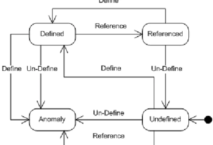
Generally, Static Program Analysis is based on the formal semantics of the program, which can be fully automated by leveraging compiler features. Among different kinds of this approach, Data Flow Analysis is routinely used in compilers, to detect compile-time syntax bugs, detect potential run-time bugs (such as unassigned variables), and to find opportunities for optimizing the code. This approach is based on the data flow relations between statements in programs (by using Control-Flow Graph (CFG) representation of program). After extracting the CFG, the associations between the definitions and uses of the variables is produced, which is needed to be covered in a given coverage criterion. Finally, the test suite is created using a finite number of paths from previous step. Data-flow testing is a white box testing technique that by tracing the lifecycle of a piece of data (e.g. a variable) and looking out for its inappropriate usage during definition (declaration/assignment), usages, and disposal (or undefinition) can be used to detect coding errors or potential bugs such as improper use of data. A famous example of the usage of this technique is indicating the usage of a variable after its disposal, which is certainly a bug to be addressed. Figure 2.1 shows the three basic actions on variables, acting as triggers to state transitions of variables and their effects:
Figure 2.1: Basic actions on variables for data flow analysis
Regardless of the approach type, constructing a control flow graph of the code is the first step of any data-flow based technique for examining the potential erroneous patterns. It is a directed graph where the nodes represent the program statements such as definition, computation and predicates while the edges represent the flow of control between program statements. In this part, some basic definitions from data flow analysis are provided which, most of them are taken from White (1987):
• A basic block: A maximum sequence of program statements such that if any one statement of the block is executed, then all statements in the block are executed.
• A control flow graph (CFG): A directed graph that represents the structure of the program. Nodes are basic blocks, and edges represent potential control flow from node to node.
• A def (definition): A location in the program where a value for a variable is stored into memory (assignment, input, etc.).
• A use: A location where a variable’s value is accessed; either in a computation, as a functional parameter, in an output statement, or in a decision.
7
• A def-clear path for a variable X through the CFG: A sequence of nodes that do not contain a definition of X.
• An actual parameter: Located in the Caller, and its value is passed to Callee. • A formal parameter: Located in the Callee, and its value is assigned from Caller. • The interface between two units: Is the mapping of actual to formal parameters
Generally, data flow analysis techniques are grouped into two categories: static or dynamic. The static analysis algorithms can detect errors within the program, without executing it, but do not work for those parts of the code which contain individual array elements, pointers, reference variables, or reference types, in which the index of corresponding variable data is generated dynamically during execution hence we can’t guarantee what state it has in compile time [19]. Another weakness of static analysis algorithms is that they might denote a certain piece of code to be anomalous which is never executed and hence not completely anomalous [13]. On the other hand, dynamic analysis algorithms can tackle those challenges, but are only performed on those parts of the program which are accessed during execution. Thus, static and dynamic analysis are considered as complementary approaches.
In dynamic analysis, in order to uncover possible bugs for a piece of data during the execution of the code, based on the traces of every definition of it to each of its usages and also every use of it to each of its definitions, some test cases are created. Various strategies are employed for the creation of the test cases, which follow the basic approach proposed by Huang [21]. In his approach, the program under test is instrumented with instructions, called probes, to report the actions that are performed upon the program’s variables to detect probable data flow anomalies. There have been dynamic data analysis approaches for both structured (i.e. procedural or non-object-oriented) and object-oriented programs, which will be discussed in more details in section 3 (related work sect).
2.2. Coupling-based Testing
While object-oriented guidelines facilitate the process of systems’ analysis, design, and implementation, testing of these programs is complicated by the fact that software being tested is often constructed from a combination of previously written, off-the-shelf components with some new components developed to satisfy new requirements, i.e. the source code of the previously written components is often unavailable, yet objects in the new components will interoperate via messages with objects in the existing components. The structural characteristics and new features in OO programs, such as encapsulation, inheritance, and polymorphism change the requirements for mutation testing. A major difference for testers is that OO software changes the levels at which testing is performed, which in [10] has been classified four levels of: (1) intra-method; (2) inter-method; (3) intra-class; and (4) inter-class.
In [8], Z. Jin and A. J. Offutt divided coupling types into four groups, which are defined specifically for testing purposes. The terminologies come from Constantine and Yourdon (1979), Page-Jones (1980), and Offutt et al. (1993):
• Call coupling occurs when A calls B or B calls A but there are no parameters, common variable references, or common references to external media between A and B.
• Parameter coupling refers to all parameter passing. Occurs when some record or scalar variable in A is passed as an actual parameter to B and is used in a computation or in a predicate; Or when a formal parameter in A is passed to B as an actual parameter, and B subsequently passes the corresponding formal parameter to another unit without B having accessed or changed the variable.
• Shared data coupling refers to procedures that both refer to the same data objects. • External device coupling refers to procedures that both access the same external medium.
8
Besides automation and scalability, deciding when to stop testing is another important aspect of a testing approach. Usually, the entire domain of software systems is effectively infinite, and cannot be entirely searched. Thus, Adequacy Criteria are defined for test designers and testers for this purpose. Integration testing must be guided by the modularization, and at a higher level of abstraction than unit testing; i.e. by assuming that the units under test had been successfully passed isolated unit tests as atomic building blocks and focusing on their interconnections because otherwise the integration testing would not be a meaningful and applicable process.
The coupling-based testing criteria described in [10] are based on the design and data structures of the program, and on the data flow between the program units. Thus, data flow definitions are needed to support coupling testing criteria definitions. Some of these basic definitions have been described in 2.1. Coupling-based specific definitions are provided in the following section. Then the kinds of testing that should be done on the coupling types are described, and then four different test criteria are defined, each of which requires a different amount of testing.
2.2.1. Coupling-based testing definitions
Z. Jin and A. J. Offutt (1998) presented several definitions by which the coupling-based testing criteria can be defined formally:
• P is an arbitrary unit in the system
• GP = (NP, EP) is the control-flow graph, where NP is the set of nodes in P and EP is the set of edges.
• VP is the set of all variables referenced in P.
• def(P, V) is the set of nodes in unit P that contain a definition of a variable V, • use(P, V) is the set of nodes in P that contain a use of V.
• Call_site is a node in P1 from which P2 is called.
• Call(P1, P2, call_site, x → y): TRUE if unit P1 calls P2 at call_site and actual parameter x is mapped to formal parameter y. This is variable specific; if there is more than one parameter, they are analysed one at a time. The value is FALSE if there is no such call at the given call_site. • Return(v): Nodes from which values for v are returned in a unit. Note that this includes explicit
return statements as well as implicit returns at the end of units.
• Start(P): The first node in P. It is assumed that there is one entry point.
• Coupling-def: A node that contains a definition that can reach a use in another unit on at least one execution path. There are three types of coupling-defs:
1. Last-def-before-call: The set of nodes that define x and for which there is a def-clear path from the node to the call_site in P. More formally:
lbc-def(P, call_site, x) = {i, i ϵ NP | node i has a definition of variable x ˄ there is a def-clear path with respect to x from node i to call_site}.
2. Last-def-before-return: When values are returned (e.g. through call-by-reference parameters or a return statement), then last-def-before-return is the set of nodes that define the returned variable y, and for which there is a def-clear path from the node to the return statement. This is formally defined as:
lbr-def(P, y) = {j, j ϵ NP | y is defined in node j ˄ there is a def-clear path with respect to
y from j to Return(y)}.
3. Shared-data-def: In the case of shared data coupling, coupling-def is defined as the set of nodes that define a non-local or global variable g in P1 that is used in P2, and for which there is a def-clear path from the def to the use.
Note that it is not necessary that either P1 call P2 or that P1 call P2; the def-clear path can go through an arbitrary sequence of calls and returns. It is formally defined as:
9
Shared-def(P1, P2, g) = {i, i ϵ NP1 | i ϵ def(P1, g) ˄ g is a non-local or global variable ˄ there is a def-clear path with respect to g from the definition in P1 to the use in P2}. • Coupling-use: A node that contains a use that can be reached by a definition in another unit on
at least one execution path. There are three types of coupling-uses:
1. First-use-after-call: In the case of call-by-reference parameters, first-use-aftercall is the set of nodes i in P1 that have uses of x and for which there exists a def-clear path with no other uses between the call statement for P and these nodes. This is formally defined as: fac-use(P, call_site, x) = {i, i ϵ NP | node i has a use of variable x ˄ there are no other uses or defs between call_site and node i}.
2. First-use-in-callee: In the case of call-by-value parameters, first-use-in-callee is the set of nodes for which parameter y in P has a use, and there is at least one def-clear path with no other uses from the start statement to this use. This is formally defined as:
fic-use(P, y) = {j, j ϵ NP | ((y has a C-use at node j) ˅ (y has an I-use on edge (i, j), i ϵ NP) ˅ (y has a P-use on edge (i, j), i ϵ NP)) ˄ there is a path with no other use or def of y between Start(P) and node j}.
3. Shared-data-use: In the case of shared data coupling, coupling-use is defined as the set of nodes that use a non-local or global variable x. This is defined as:
Shared-use(P, g) = {i, i ϵ NP | i ϵ use(P, g) ˄ g is a non-local or global variable}.
• External-reference: In the case of external coupling, the pair of references (i, j) to the same external file is called an external-reference. It is defined as:
External-ref(i, j) = {(i, j), i, j ϵ P, i, j reference the same external file or device}.
• Parameter coupling path. For each actual parameter x, and each last definition of x before a call_site, there is a parameter coupling path from the last definition, to the call_site, and to each first use of the formal parameter y in P2. This is defined as:
o parameter-coupling(P1, P2, call_site, x, y) = {(i, j), i ϵ NP1, j ϵ NP2 | i ϵ lbc-def(P1, call_site, x) ˄ j ϵ fic-use(P2, y)}.
o If a parameter x is a call-by-reference, then there is also a parameter coupling path from each last definition before return of the formal parameter y in P2 to each first use after call of actual parameter x in P1. This is defined as:
parameter-coupling(P1, P2, call_site, x, y) = {(j, i), i ϵ NP1, j ϵ NP2 | j ϵ lbr-def(P2, y) ˄ i ϵ fac-use(P1, call_site, x)}.
• Shared data coupling path. For each non-local or global variable g that is defined in P1 and used in P2, and each definition of g in P1, there is a shared data coupling path that is definition-clear with respect to g from the definition to each first use of g in P2. It is defined as:
Shared-data-coupling(P1, P2, g) = {(i, j), i ϵ NP1, j ϵ NP2 | i ϵ shared-def(P1, P2, g) ˄ j ϵ
shared-use(P2, g)}.
• External device coupling path. For each pair of references (i, j) to the same external device, an external device coupling path executes both i and j on the same execution path.
2.2.2. Coupling-based testing criteria
The coupling-based testing criteria introduced by A. J. Offutt and Z. Jin (1998) are extensions of the standard data flow levels (Frankl and Weyuker, 1988). They are written in a general form, so that they can be applied to all three types of Parameter/Shared Data/External Device Coupling path defined in the previous section. As before, P1 and P2 are units in the software system.
• Call-coupling Criterion: All call_sites must be covered.
• All-coupling-defs Criterion: For each coupling-def of each variable in P1, at least one coupling path to at least one reachable coupling-use in P2 must be covered.
• All-coupling-uses Criterion: For each coupling-def of each variable in P1, at least one coupling path to all reachable coupling-uses in P2 must be covered.
10
• All-coupling-paths Criterion: For each coupling-def of a variable x in P1, all coupling path to
all reachable coupling-uses in P2 must be covered, i.e. all coupling paths must be covered. However, if there is a loop, in which the number of sub-paths becomes infinite, all-coupling-paths requires two test cases; one for the case when the loop body is not executed at all, and another that executes the loop body some arbitrary number of times. This technique depends on unique sets of nodes within the coupling paths.
The above testing criteria are written in their subsumption hierarchy order. For example, if and only if every test set satisfies All-coupling-uses criterion, then they satisfy All-coupling-defs criterion either.
2.3. Interface Mutation
As discussed in section 1.4.2, mutation testing is an approach for examining the test suite, not the SUT itself. I.e. by applying some change on the (source code or compilation outputs of the) SUT, so that without generating the compilation error, the logic of the program is changed, and then we can experiment the program on a set of test cases, we can observe if the deliberately injected faults are reflexed in the test results. The syntactic changes are based on some rules (or mutation operators). We suppose the mutants as being faults, although it is possible that the original program was faulty and the mutant is correct, or the mutant has no effect on the functional behavior of the program (equivalent). If the test set can kill all non-equivalent mutants, the test set is declared mutation-adequate [11]. Although it is possible to make multiple changes at a time (called higher-order mutants), most mutation systems recommend just one change (one-order mutants). The mutation score is the percentage of non-equivalent mutants killed. For a program P, let MT be the total number of mutants produced with respect to a
particular fault model F. Let ME and MK be the number of equivalent and killed mutants. The mutation
score of the test set T with respect to the fault model F is defined as: MS(P, T, F) = MK/(MT−ME)
While at the unit level, testing is concentrated on verifying whether each unit performs its required function by focusing on the algorithmic aspects, the goal of integration testing is to put the units in their intended environment and exercise their interactions. “It is difficult to generate effective mutants that target integration tests only. Deciding where in the AUT’s code to apply mutation operators to target integration tests requires specific knowledge of how different components interact in applications. That is, an integration mutant should create an error state in one component with assurances that this error state will result in a failure in some other components. Generating mutants by applying mutation operators to statements and expressions whose values never reach integrated components leads to wasted time and effort and doing so increases the cost and reduces the effectiveness of mutation testing” [3]. Interface Mutation provides one such criterion. Regardless of the used programming language, mutation operators can be applied at three levels. (1) Unit level, in which the mutation operators are applied on individual program methods. (2) Integration level, which targets communication between two units. (3) Class level, which modifies multiple functions in a single class.
As described in previous section, a major difference of testing the OO software is that we can define different levels of abstraction at which testing is performed. Another difference for these types of software is that an OO-specific mutation system has this possibility to extract information and execute programs from an OO standpoint (control, data, inheritance, and polymorphic relationships among system and user-defined classes). Most of these have focused on developing mutation operators rather than developing algorithms and techniques for implementing them in usable and efficient tools, together with some sets of class mutation operators that have been developed for this purpose.
For describing Interface Mutation, four different non-mutually exclusive types of data exchange between units has been mentioned in [18], which can be summarized as these three kinds:
11
• Parameters passing (by value or by reference, such as output parameters in some programming languages).
• Global variables passing.
• Return values (as in return commands in C).
Similar to coupling based analysis definitions, for a function F, its interface is precisely defined by its formal parameters, the global variables it accesses, and the code it implements. The connection between units are defined by function calls. When applying Interface Mutation, unlike traditional mutation, the syntactic changes are made only at the interface related points or connections between units. Based on variables and expressions concerned with these types of data transfers, a collection of Interface mutation operators has been introduced, which will be discussed later in this section. Although the same concepts can be applied to a variety of languages, mutant operators’ implementation is dependent to the chosen programming. In this study, the Interface Mutation operator set applicable for the C# language is provided, first according to [18, 10], and then restricted to a more restricted set of operators mentioned in [3]. Table 1 lists Interface Mutation operators declared in [18]:
Table 1. Interface Mutation Operators
DirVarRepPar Replaces interface variable by each element of P DirVarRepGlo Replaces interface variable by each element of G DirVarRepLoc Replaces interface variable by each element of L DirVarRepExt Replaces interface variable by each element of E DirVarRepCon Replaces interface variable by each element of C DirVarRepReq Replaces interface variable by each element of R IndVarR,epPar Replaces non interface variable by each element of P IndVarRepGlo Replaces non interface variable by each element of G IndVarRepLoc Replaces non interface variable by each element of L IndVarRepExt Replaces non interface variable by each element of E IndVarRepCon Replaces non interface variable by each element of C IndVarRepReq Replaces non interface variable by each element of R
DirVarIncDec Inserts/removes increment and decrement operations at interface variable uses IndVarIncDec Inserts/removes increment and decrement operations at non interface variable uses DirVarAriNeg Inserts arithmetic negation at interface variable uses
IndVarAriNeg Inserts arithmetic negation at non interface variable uses DirVarLogNeg Inserts logical negation at interface variable uses IndVarLogNeg Inserts logical negation at non interface variable uses DirVarBitNeg Inserts bit negation at interface variable uses IndVarBitNeg Inserts bit negation at non interface variable uses RetStaDel Deletes return statement
RetStaRep Replaces return statement CovAllNod Coverage of all nodes CovAllEdg Coverage of all edges
ArgRepReq Replaces arguments by each element of R ArgStcAli Switches arguments of compatible type ArgStcDif Switches arguments of non compatible type ArgDel Remove argument
ArgAriNeg Inserts arithmetic negation at arguments ArgLogNeg Inserts logical negation at arguments ArgBitNeg Inserts bit negation at arguments ArgIncDec Argument Increment and Decrement FunCalDel Removes function call
12
This set of interface mutation operators was later reduced to a list of 10 more efficient operators by M. Grechanik and G. Devanla for developing jMINT in [3]. More details on the application of theses operators will be discussed in section 8. Since C# and Java have a very similar syntax, these operators with some minor changes (such as using base instead of super for ISK) were used as the basis of our evaluation in this study as well.
2.4. Roslyn API
In this part, based on the tutorial article of .NET Compiler Platform ([1]) a review of Roslyn is provided. Prior to Roslyn, compilers operated as black boxes which accepts source code as input and Upon compilation, either a binary is produced for successful compilation or error(s) when the compilation fails. Roslyn is the code name for the .NET compiler as a service offering, which in addition to the general source code compilation performed by compilers, provides “hook points” – events (such as parsing a constructor or a method or even a variable within the source code), through which subscribers (bespoke code or a code analyzer) can participate in the compilation process and by full access to the entire syntax tree and/or semantic table, obtain rich information about the input source code.
Figure 2.4.1. Relation between Workspace, host environment, and tools
Roslyn-based code analyzers are .NET libraries which can be developed in both C# and VB.NET. They can either be packaged as Visual Studio extensions1 or as NuGet packages2 which require no installation and apply only to the C# projects which depends on them. Roslyn SDK Preview includes the latest drafts of new language object models for code generation, analysis, and refactoring. The rest of this subsection provides a conceptual overview of Roslyn. Further details can be found in the walkthroughs and samples included in the SDK Preview.
1 https://msdn.microsoft.com/en-us/library/bb166030.aspx 2 https://www.nuget.org/
13
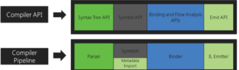
By providing an API layer that mirrors a traditional compiler pipeline, Roslyn exposes the C# and Visual Basic compiler’s code analysis. This pipeline includes four phases, which are implemented as separate components and an object model is surfaced corresponding to each of those phases, that allows access to the information at that phase. In the first phase the source is tokenized and parsed into syntax that follows the language grammar, so it is called the parse phase. This phase is exposed as a syntax tree. In the second phase (the declaration phase), some named symbols are created from analysing the declarations from source and imported metadata. This phase is exposed as a hierarchical symbol table. In the third (bind) phase, those named symbols are matched to identifiers in the code. This phase is exposed as a model that exposes the result of the compiler’s semantic analysis. Finally, in the emit phase, an assembly is emitted from building up all the information built up by the compiler. This phase is exposed as an API that produces IL byte codes.
Figure 2.4.1. C#/VB.Net Compiler Pipelines vs. Roslyn Compiler API
These components together as a single end-to-end whole build up C# or VB compilers. The language services that are used to power the C# and VB experiences in Visual Studio vNext have been rebuilt by the public Compiler APIs to ensure that they are enough for building world-class IDE features. For example, features such as the code outlining, and formatting features use the syntax trees, while the Object Browser and navigation features need more analytical information from the code to operate, so they use the symbol table. More complicated features such as refactoring and Go to Definition which require more comprehensive information of the entire project’s structure use the semantic model. There are also some features (such as Edit) that need accessing to the information of all phases. Through the “Roslyn” End-User Preview, some of these experiences may have been embedded into Visual Studio 2013. Independently of Visual Studio without requiring the End-User Preview, this preview is required in order to build and test applications built on top of Roslyn SDK meant for integration into Visual Studio though Roslyn APIs can be used in your own applications.
As the open source C# compiler API has been provided just a few years ago, most of the state-of-practice integration test tools are in Java rather than C#. Since the suggested comprehensive solution for integration test automation of .Net programs uses a combination of data flow, coupling, and mutation techniques, this section includes some elite state-of-the-art/practice works in each of these contexts. However, as the open source C# compiler API has been provided just a few years ago, most of the state-of-practice integration test tools are in Java rather than C#. However, since Java and C# are equally full object-oriented languages with a very similar syntax, it makes sense to leverage such solutions in this study.
14
3. Related Work
In this section the placement of our work in a context and comparing it with previously published works and results in the field, to create an expectation of the contribution is discussed. Together with background, this section is intended to introduce "state of the art" / "state of practice", deficiencies, and the importance of the task and what the work should be compared with. Some software faults that happen in the interfaces between units cannot be detected during unit testing; Thus, specific tests must be designed to detect integration-specific faults.
3.1. Interface Mutation Tools
Since interface mutation techniques have been used as a part of this study (the evaluation part), a couple of mutation-based methods/tools are discussed in the remainder of this section. In 2004, Y.-S. Ma, J. Offutt, and Y. R. Kwon presented a method to reduce the execution cost of mutation testing for OO programs by using two key technologies, mutant schemata generation (MSG) and bytecode translation. This method adapted the existing MSG method for mutants that change the program behavior and used bytecode translation for mutants that change the program structure. A key advantage was in performance: only two compilations were required and both the compilation and execution time for each were greatly reduced. The tool described there implements both inter- and intra-class mutation operators. It primarily focuses on studying the inter-class, or OO, operators. Much is already known about intraclass (statement level) mutation operators.
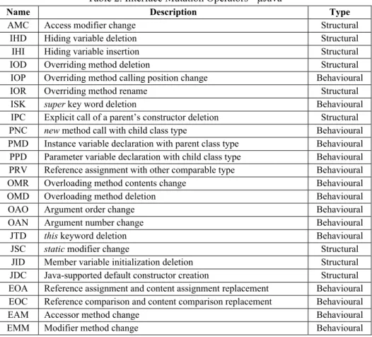
Later, in [10], this set of operators was updated by the following list of operators specified for Java programming language, which were used in developing µJava mutation generator application:
Table 2. Interface Mutation Operators - µJava
Name Description Type
AMC Access modifier change Structural IHD Hiding variable deletion Structural IHI Hiding variable insertion Structural IOD Overriding method deletion Structural IOP Overriding method calling position change Behavioural IOR Overriding method rename Structural ISK super key word deletion Behavioural IPC Explicit call of a parent’s constructor deletion Structural PNC new method call with child class type Behavioural PMD Instance variable declaration with parent class type Behavioural PPD Parameter variable declaration with child class type Behavioural PRV Reference assignment with other comparable type Behavioural OMR Overloading method contents change Behavioural OMD Overloading method deletion Behavioural OAO Argument order change Behavioural OAN Argument number change Behavioural JTD this keyword deletion Behavioural JSC static modifier change Structural
JID Member variable initialization deletion Structural JDC Java-supported default constructor creation Structural EOA Reference assignment and content assignment replacement Behavioural EOC Reference comparison and content comparison replacement Behavioural EAM Accessor method change Behavioural EMM Modifier method change Behavioural
15
A mutation tool named µJava [10] based on the MSG/bytecode translation method was built and used to measure the speedup over the separate compilation approach. Experimental results showed that the MSG/bytecode translation method was about five times faster than separate compilation.
In 2016, as an integration-level-testing-specific improvement on µJava, M. Grechanik and G. Devanla in [3] proposed a theory and a solution for generating mutants that specifically target integration tests. By addressing a fundamental problem of mutation integration testing - how to determine the effectiveness of integration test suites efficiently - they formulated a fault model for integration bugs that uses static dataflow analysis to obtain information about how integrated components interact in an application. A root of this problem that they tackled was that applying mutation operators indiscriminately to all instructions results in a very large number of mutants, many of which are not related to integration tests because not all paths end at an integration point. An integration bug can result from an error that is outside the scope of the integrated classes. For example, in code below, suppose that an error is injected where the operator “>” in the conditional expression of the second line is replaced with the operator “<”. Then, the components Employee and Helper will interact instead of the components Employeeand Manager. This example shows that a small semantic error leads to changing the control flow at runtime that results in not invoking proper integrated components:
They implemented their approach in Java Mutation Integration Testing (jMINT) to generate mutants that specifically target integration tests. Integration mutants were then generated by applying 10 mutation operators (mentioned in section 5) to instructions that lie in dataflow paths among integrated components and evaluated on five open-source applications. In comparison to μJava, their approach showed a considerable reduction in the number of generated mutants with a strong power to determine inadequacies in integration test suites.
3.2. Integration-level test case for OO applications – A data flow based approach
As discussed, by examining the flow of control between the various components, we can design and select test cases. Using data-flow testing leads to a richer test suite concentrating on improper use of data due to coding errors. In [14], S. Z. Waheed and U. Qamar proposed a novel approach for test case generation of object-oriented integration testing. There, search space is reduced by selecting the coupling methods that are directly involved in integration. Further def-use analysis helps in achieving the desired object states for proper interfaces testing, representing methods in testing tree. In their algorithm, they use data flow coverage criteria. Each DU path is considered in selecting method sequence to generate the desired state for integration testing. Instead of generating the method sequence for branch coverage they used coupling based data flow coverage for test case generation. It generates a Tree that contains coupling method as root and all the possible def-use paths can be represented by the sub nodes of that tree. Their approach assumes that each unit is already tested and validated. It only requires testing the interfaces, through which units are interacting with each other. This is recursive process and output is the tree, representing method sequences with coupling method as root. Tree representation is the output
16
of our test sequence generation algorithm. There are variable number of methods (nodes) involved in each test case. Root node represents the coupling method that involved in integration and child nodes are predecessor methods selected based on DU analysis.
3.3. Integration-level test case for .Net applications using Roslyn APIs
Inspiring from this approach and jMINT [3] (discussed later in this section), a tool was introduced in [1] as an automated solution and tool to identify integration scenarios and generate test cases (in the form of method call sequences) for .NET applications. It works by analyzing the code and automatically identifying class couplings, interacting methods, as well as invocation points. Moreover, the tool also helps and supports testers in identifying timing issues at integration level by automatic code instrumentation at invocation points. Hence, this work was the first in utilizing Roslyn features for automatic integration analysis and integration test case generation. The main contribution of this study has been based on the future work of this paper.
3.4. What is missing
Regarding the mutation techniques, generally speaking, although they have been exercised for many years in literature, and have proved their efficiency in the context of software testing, but beyond the two general weaknesses of mutation analysis (the cost and equivalence decision), mutation is basically aimed to evaluate the comprehensiveness of test suites, not testing the SUT directly. Thus, they can just be considered as parts of the whole process of test automation.
Besides these, when it comes to the integration-level test case generation using data flow approach, although the initial results apparently showed significant improvement in method sequence generation, but they need to be furthered tested on complex projects to show their strength. Moreover, no cross-checked has been done by other techniques to prove their correctness.
17
4. Problem Formulation
Regardless of the context of project, the methodology supplied for the development process, or the used tools and technologies, manually software testing is prone to several challenges:
• Being highly dependent to skilled testers, mastering both development and business domain requirements.
• Difficulties in proper documentation that includes descriptions and steps to reproduce the defects.
• Dealing with intermittent bugs that happen occasionally, under certain circumstances. • The decision of when to stop the testing, etc.
In agile software development however, some of these challenges are even bolder: • Prioritizing the test cases in sprints.
• Reusing the test scripts in CI/CD or in Regression testing. • Training newly-comer testers, etc.
Besides these, integration level testing, for its part, has some key differences that makes manual testing even more difficult to be supplied. For example, many integration-level failures generally happen in the messages between integrated units, not in the code as they would be in unit failures. Unfortunately, most testing tools are focused on testing code and GUIs, not testing messages. As another challenge, most attempts at integration testing do not recognize that users of the system have different expectations of the system and will use the “integrations” differently depending on those expectations and their business needs.
Since software systems are constantly growing in size and complexity, manual testing becomes time consuming, sometimes even prohibitive. Therefore, software tests should be automated, not only for efficiency reasons but also for reproducibility. In the field of automatic integration test case generation, little work has been done in practice, especially for .Net applications for which, the compiler features had not been publicly available, so the static analysis of those codes was almost impossible until a few years ago. Therefore, providing test automation tools seems required for industrial integration-level testing. By considering the features recently provided by Roslyn APIs, which has made the .Net applications’ static analysis feasible, in this thesis we try to figure out:
1. How can static analysis approaches such as coupling-based or data-flow analysis approaches be used to generate integration-level test-cases?
2. How to automatically generate integration-level abstract test-cases for object-oriented .Net programs by supplying the Roslyn C#/VB.NET compiler APIs using these techniques.
18
5. Method
The test case generation in this thesis was theoretically based on a static analysis technique, combining data-flow and coupling analysis of the code. Compared with other approaches, the advantage of data flow analysis for automatic test case generation is that, since they just rely on the code, they don’t require fully modeled development process (as needed for model-based testing). Besides that, they cost much less in terms of time and effort. Another reason for selecting it was the ability to be fully automated and reused. Finally, the last advantage of this technique is that the generated abstract test cases can be used for further concrete ones in order to support maximum possible automation. So, these were the reasons for choosing the dynamic data flow approaches mentioned in [14, 3, 1] as baselines for this thesis. This technique includes: Read the source code to identify the user-defined classes, extracting the list of
parameter-coupling methods, and for each of them, listing all the class functions that directly or
indirectly modify the used class fields in their body. After processing all those coupling methods, for each of them a path is constructed whose end node is the coupling method and contains the list of functions that can affect its field variables recursively as previous/ children nodes of the path leading to that coupling method.
The implementation of automating the algorithm was done in C# language in Visual Studio IDE by using Roslyn Syntax Tree API and Symbol API. The Compiler APIs of Roslyn do the analysis of the code, extracting syntax tree and semantics of code statements and blocks, detecting class definitions, class methods, class method signatures and parameters, class fields, and also class fields definitions and usages in the body of each class method.
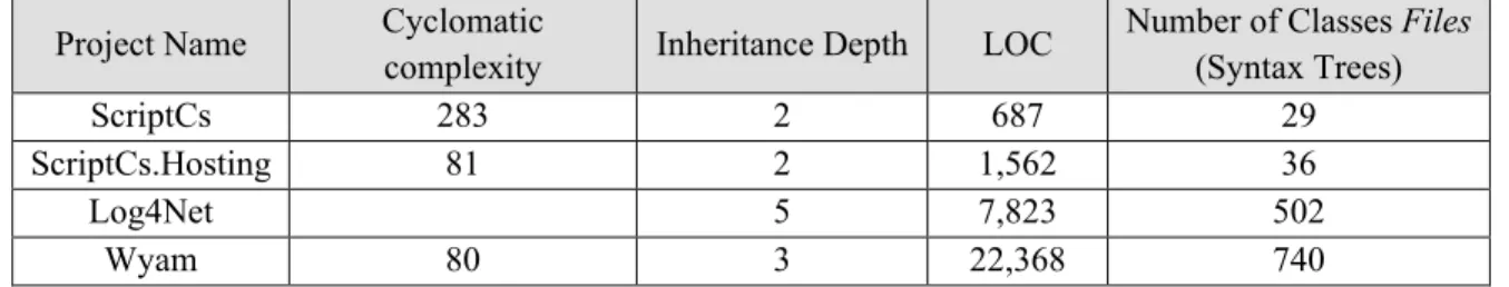
Then, this automatic test case generation solution was experimented by exercising it on some sample C# project as benchmarks. These three benchmarks (Log4Net, ScriptCs, and Wyam [23-25]) were selected among a couple of well-known open-source C# programs. Regarding the benchmark codes, those C# projects should have been selected that, first, contained necessary specifications for being able to be mutated by those mutation operators, and second, the solution could be run on them without throwing exceptions (because of not supporting some OO features such as generics).
Clearly, all these works would not provide any added value if the quality of generated test cases had not been evaluated. Thus, a considerable amount literature reviewing, and investigations was done for finding the best method for this purpose. At the end, the interface mutation technique was chosen for the test cases’ quality assessment because they are actually the only well-known approaches dealing with the validity of test cases, of which effectiveness and efficiency have been proved through several studies and experiments, while other techniques deal with the validity of the software-under-test. The evaluation is based on finding out: To what extent the generated test paths have the ability of covering the mutations?
Three methods were figured out for this assessment:
A. Generating test paths for each mutation and comparing them with the original one; e.g. comparing the number of test paths, or comparing the details of corresponding test path. B. Generating test paths just for the original code, and investigate the generated paths to see what
percentage of mutations they cover; i.e. for each mutation operator, figuring out if any test path in any of test path sets contain a function which is affected by that mutation operator? C. Doing static analysis based on the programming language syntax and semantics.
Clearly, the first two methods are more complete than the last one but generating a complete set of mutations -even by a limited set of interface mutation operators- is a very costly way. For this reason, and also since this study is in the context of a specific programming language (C#), the third method was chosen for comparison step.
19
For mutation-based evaluation of the algorithm, the only state-of-practice tool written in C# found was
Fettle [16], which generates mutants for .Net applications but since no literately known technique has
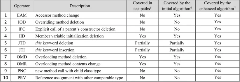
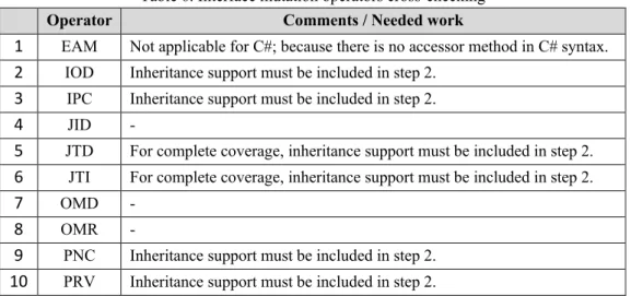
been mentioned about interface mutation generation, it could not be used as a gauge for this study. On the other hand, the previously mentioned mutation tool (jMINT) was in Java and could not be executed on a C# project. Thus, we decided to evaluate the solution manually according the 10 mutation operators used in jMINT:
Table 3. Interface Mutation Operators - jMINT 1 EAM Accessor method change
2 IOD Overriding method deletion
3 IPC Explicit call of a parent’s constructor deletion 4 JID Member variable initialization deletion 5 JTD this keyword deletion
6 JTI this keyword insertion
7 OMD Overloading method deletion 8 OMR Overloading method contents change 9 PNC new method call with child class type
10 PRV Reference assignment with other comparable type For each mutation operator, the cross-check can be done by:
I. Applying it on the source code.
II. Generating test path from mutated code.
III. Checking if the mutation was reflected on the generated test paths. More descriptions on the work will be provided in section 7.
20
6. Ethical and Societal Considerations
21
7. Contribution
Before starting this section, it should be noted that since a major part of this study’s contribution was implementing the automation of test cases generation by a programming language, we could not have such a lengthy section, especially because the theoretical bases have been described in sections 2 and 5, and some major parts of contribution have been explained within the related works and results sections.
Before describing the details of the practical contribution in this study, let us propose a higher-level solution to “automatic integration-level testing” rather than “automatic integration-level test-case
generation”, and have a short explanation on the generic solution which - considering the open
source compiler APIs as applicable code analysis tool - is potentially achievable for .Net applications. Then, we can have a better sight of this thesis’s contribution, how it deals with the research questions, and how it is related to the general problem of “integration-level test automation for OO applications written in .Net”.
According to the literature reviews on a set of theories and tools available for testing at integration-level, object-oriented testing, and .Net applications’ code analysis it was concluded that by using a combination of data-flow analysis and coupling-based analysis as the main theoretical base (and other helping techniques such as boundary value, input/output partitioning, or fault injection) for test-case generation and the Roslyn APIs as code analysis/instrumentation tool, the following steps can lead to the most automatic integration-level testing framework possible for object-oriented .Net applications:
1. Cohesion analysis: since on one hand, the integration-level testing depends on the coupling degree of the code, and on the other hand, the coupling degree of the code is related to the cohesion level of the code in some ways. I.e. usually increasing the cohesion degree of the code results in decreasing the coupling level of it.
2. Improving the cohesion level of the code: 2.1. Removing unnecessary variables.
2.2. Changing unnecessary public functions into private ones. 2.3. Removing unnecessary private functions.
2.4. Removing conditions’ conflicts. 2.5. Removing conditions’ overlaps.
2.6. Removing unnecessary conditions before/after invocation points, etc. 3. Integration-level abstract test cases generation
4. Code instrumentation for measuring all-coupling-paths criteria: Allows inserted instructions to report actions to the meta-model. The techniques presented range from compile-time instrumentation to runtime-monitoring.
5. Code instrumentation for assertions (base values will be set later) – some primary values can be set by using boundary value or input/output partitioning, and fault injection techniques. 6. Generating semi-concrete test cases in JSON/XML, including:
22
6.2. Arguments' list of each coupling method, including their name, type, and a default value; 6.3. Input element for setting base values for the assertion of each coupling parameter; 7. Generating an executable application from the initial projects after code injection, which gets
its inputs from that semi-concrete test cases generated in previous step.
8. Completing the generated test cases by setting concrete values for coupling methods' parameters and assertions' base values (by test engineer).
9. Executing the generated executable application, according to the concrete test cases; 9.1. Reporting all-coupling-paths coverage: coupling based meta-model instrumentations; 9.2. Reporting test pass percentage: data-flow based assertion instrumentations;
Among these steps, this study’s contribution engages with the third step, which is about generating
abstract test cases at integration level for OO applications written in .Net framework, in three steps,
each corresponding to one of the research questions:1) finding a theoretical solution suitable for generating abstract test cases at integration level, 2) automating that solution, and 3) evaluating the solution. So, the work has been done in the following steps:
• Choosing and improving a technique based on the combination of data-flow analysis and object-oriented concepts such as coupling for integration-level test-case generation.
• Creating a solution for automating that technique to be used on Object-Oriented .Net applications:
• Implemented in C# language, • Visual Studio as IDE.
• By using the newly presented .Net compiler named Roslyn. • Running the solution on a couple of C# projects as benchmarks.
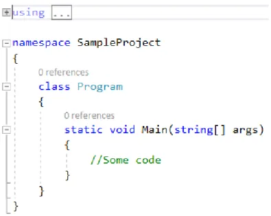
• Evaluation of the generated test cases’ quality using an Integration-Level Mutation technique. As discussed earlier, the test case generation technique has been theoretically based on a combination of data-flow and coupling based approaches. For answering the first research question, by having the new knowledge of Roslyn APIs’ capabilities, we tried to look for some ways to extend or improve the algorithm mentioned at section 3.2 to have an enriched set of generated test paths. One important improvement on the initial algorithm was adding call-couplings to the list of coupling methods. This improvement was so vital especially for the .Net applications because by extracting just parameter-couplings, generating a complete set of coupling paths was practically impossible. This is because for example in the applications written in C#, the first executed function in the startup project is something like what is shown in figure 7.1. i.e. a static function that has no parameter of one of the user-defined types. Therefore, if we are going to use only parameter coupling, first, we will miss the entry point of control flow, so the extracted coupling paths will lack of the most important function call sequence starting from the application’s entry point. Second, the methods in the generated coupling paths of each class will contain only the methods of itself.
23
Figure 7.1. Common entry point for C# solutions
Another similar extension was adding constructors and destructors besides functions or methods. This change also enriched the set of generated test paths with new paths which had not been extracted before. The last change was adding struct dependencies besides class dependencies. As a result, we had this updated version to be implemented at the next step in order to answer the second research question:
1. Read in as input the solution and identify the projects’ structures including user-defined
classes/structs.
2. Extract the list of parameter and call coupling methods/constructors/destructors in the project. 3. For each coupling method:
3.1. Identify list of class/struct field variables that are used in its body.
3.2. Identify other class/struct methods that can modify the value of the previously identified class/struct fields.
3.3. Perform the last two steps recursively until all methods in that class/struct that modify the collected class/struct fields and variables are identified.
4. For each coupling method, construct a path whose end node is the coupling method, and the list of methods that can affect its field variables recursively as previous/ children nodes of the path leading to that coupling method.
5. Print out the generated paths, grouped by the classes/structs containing each coupling method. Besides the two enhancements mentioned above, which have been applied on the algorithm, compared with previous implementations of similar algorithms (in [1] and [14]), another improvement on the implementation was also done. This improvement deals with the step 3.1, in which the used class fields of each coupling method is retrieved. In the current automated solution, not only being at the right side of simple assignments is a merit of extracting a field’s usage, but also four other types of usages are diagnosed for class fields. Three of them which are direct usages
24
are: a) being in the parameter list of a coupling method call, b) attending in the predicate(s) of an if statement, and c) being in (part of) a return statement. The last added new usage type, which can be referred to as indirect usage is retrieved recursively from the used class fields of any coupling method invoked within the body of the current coupling method. By adding these new usage type diagnoses to the implementation of step 3.1, we could generate a much-enriched set of test paths, compared to the previous similar implementations.
One important issue that should be considered is that the Syntax API is not a suitable tool for extracting the list of class fields, but the Symbol API with the help of semantic metadata should be used for this purpose. That is because using only the Syntax Tree without the semantic information of the tokens for finding out the class fields can lead to errors such as counting a methods local variable with the same name as a field in its owner class, and this will result in generating a set of test paths that does not contain proper members with respect to the interface mutation operators such as “Member variable initialization deletion”, “this keyword deletion”, or “this keyword insertion”.
In order to deal with the second RQ, as said previously in methods section, a C# project was written. In this project, by supplying .NET Compiler Platform libraries, the syntax tree and semantics of the source code are analyzed and based on the analytics, the test paths can be generated. The appendices attached to the end of this report show some of these automatically generated test paths. The supplied packages in this project are:
• Microsoft.Build.Locator,
• Microsoft.CodeAnalysis.Analyzers,
• Microsoft.CodeAnalysis.CSharp.Extensions, • Microsoft.CodeAnalysis.CSharp.Workspaces, • Microsoft.CodeAnalysis.Workspaces.MSBuild. Some implementation details:
1) In the main function of the project, we iterate over all projects in the solution and for each project, we iterate over all user-defined classes, and for each of them: lists of all Parameter/Call
coupling methods are extracted by GetCouplings function, which
a) iterates over all methods/constructors/destructors in each user-defined class, and
b) calls the GetCorrespondingBaseMethod function for each invocation point found in each of those classes for knowing if it is due to a call coupling or not. Currently, this extension method that is implemented in the Utilities.cs helper class is unfortunately a performance bottleneck and should be enhanced in future.
2) After extracting all Parameter/Call coupling methods, the GenerateTestPathList function is executed for each of them to show the desired call sequences by
a) Finding the used class fields in each method, which is implemented by the GetUsedClassFieldsInMethod function) including direct uses (such as parameters, right side of assignments, conditions’ predicates, and return statements) and indirect uses (each of those four usage types by the function calls at invocation points inside the method. b) Finding the methods which define those used class fields (by calling
GetDefiningMethods function), and finally