Advances In
MICROWAVE
METAMATERIALS
ByJames A. Wigle
B.S.E.E, University of Maryland, 1991
M.S.E.E, Johns Hopkins University, 1996
A dissertation submitted to the Graduate Faculty of the
University of Colorado at Colorado Springs
in partial fulfillment of the requirements for the degree of Doctor of Philosophy
College of Engineering & Applied Science
Department of Electrical and Computer Engineering
Copyright Notice
© Copyright by James A. Wigle 2011, all rights reserved.
The author, James A. Wigle, copyrights all text, ideas, figures and photographs of this document. Any form of copying, reprinting, or publishing of this document, in any portion, is not permitted without the author‟s explicit, written, and prior permission in any form or medium. Contact the author for this written permission.
This dissertation for Doctor of Philosophy degree by
James A. Wigle
has been approved for the
Department of Electrical and Computer Engineering
by
___________________________________ John Norgard, Chair
___________________________________ Hoyoung Song, Co-Chair
___________________________________ Thottam S. Kalkur, Chair ECE
___________________________________ Tolya Pinchuk, Dept. of Physics
___________________________________ Zbigniew Celinski, Dept. of Physics
____________________ Date
Abstract
Metamaterials are a new area of research showing significant promise for an entirely new set of materials, and material properties. Only recently has three-fourths of the entire electromagnetic material space been made available for discoveries, research, and applications.
This thesis is a culmination of microwave metamaterial research that has transpired over numerous years at the University of Colorado. New work is presented; some is complete while other work has yet to be finished. Given the significant work efforts, and potential for new and interesting results, I have included some of my partial work to be completed in the future.
This thesis begins with background theory to assist readers in fully understanding the mechanisms that drove my research and results obtained. I illustrate the design and manufacture of a metamaterial that can operate within quadrants I and II of the electromagnetic material space (Ɛr > 0 and µr > 0 or Ɛr < 0 and µr > 0, respectively). Another metamaterial design is presented for operation within quadrant III of the electromagnetic material space (Ɛr < 0 and µr < 0).
Lorentz reciprocity is empirically demonstrated for a quadrant I and II metamaterial, as well as a metamaterial enhanced antenna, or meta-antenna. Using this meta-antenna I demonstrate improved gain and directivity, and illuminate how the two are not necessarily coincident in frequency. I demonstrate a meta-lens which provides a double beam pattern for a normally hemispherical antenna, which also provides a null where the antenna alone would provide a peak on boresight.
The thesis also presents two related, but different, novel tests intended to be used to definitively illustrate the negative angle of refraction for indices of refraction less than zero. It will be shown how these tests can be used to determine most bulk electromagnetic material properties of the material under test, for both right handed and left handed materials, such as Ɛr , µr , δloss, and n.
The work concluding this thesis is an attempt to derive modified Fresnel Coefficients, for which I actually believe to be incorrect. Though, in transposing I have corrected a few mistakes, and now I can no longer find the conundrum. I have included this work to illuminate the need for modified Fresnel coefficients for cases of negative indices of refraction, identifying all disparate cases requiring a new set of equations, as well as to assist others in their efforts through illumination of the potential erroneous path chosen.
Acknowledgements
This work would not be complete, if not for the help of others. My mentor Dr. John Norgard, and my in situ mentor Dr. Hoyoung Song, provided wonderful advice and guidance in my University of Colorado efforts. Indispensible, and much appreciated, technical assistance and theory were provided by Dr. Tolya Pinchuk of The University of Colorado Physics Department and Dr. Victor Gozhenko of The National Aviation University, Ukraine (Віктор Гоженко, Національний Aвіаційний Університет, Україна). I sincerely aspire to continue our relationships and expanding our knowledge of physics and electromagnetics. Mr. James Vedral significantly helped with modeling and technical discussions. It is with sincere appreciation that I thank all of you, my wife and family, and many others for the support required to complete this work. In the modified words of Sir Isaac Newton, my personal hero, efforts such as this are easy while standing on the shoulders of giants.
Table of Contents
Copyright Notice ... ii
Abstract ...iv
Acknowledgements ...vi
Table of Contents ... vii
List of Tables ... xiv
List of Figures ... xv
Chapter 1. Introduction... 1
1.1 Purpose and Chapter Descriptions ... 1
1.2 What is a Metamaterial? ... 2
1.3 Some Metamaterial History ... 2
1.4 General Metamaterials Information ... 3
Chapter 2. Metamaterial Artifacts and Curiosities ... 7
2.1 Proposed and Theorized Metamaterial Uses... 7
2.2 The Perfect Lens ... 9
2.3 Cloaking Success ... 10
2.4 Directive Emission Using Metamaterials ... 12
2.5 The Cherenkov Detector ... 13
Chapter 3. Metamaterial Theory ... 15
3.1 Introduction to Metamaterial Theory ... 15
3.2 Law of Refraction (Snell‟s Law) and Refractive Index ... 15
3.3 Index of Refraction‟s Forced Radical Sign ... 16
3.4 Snell‟s Law with a Metamaterial Twist ... 18
3.5 Permittivity ... 20
3.6 Split Ring Resonators ... 21
3.7 Narrow Frequency Bandwidths ... 22
3.8 Plasma Frequency ... 23
3.9 Physical Description of Right vs. Left Handed Materials ... 24
3.10 Proof of Snell‟s Law Radical Sign Result ... 26
3.11 Bulk Plasma Frequency ... 32
3.12 Surface Plasma Resonance ... 38
Chapter 4. Quadrant II, 10.5 GHz Metamaterial ... 48
4.1 Introduction ... 48
4.2 Design Theory ... 48
4.3 The Design ... 52
4.4 The Model ... 53
4.5 Model Results ... 55
Chapter 5. Quadrant III, 4.5 GHz Metamaterial ... 58
5.1 Introduction ... 58
5.2 Design Theory ... 58
5.4 The Model ... 60
5.5 Model Results ... 61
Chapter 6. Metamaterial Reciprocity for Quadrant II ... 63
6.1 Introduction ... 63
6.2 Test Setup for Metamaterial Reciprocity ... 63
6.3 Metamaterial Reciprocity Test Results ... 65
Chapter 7. Patch Antenna ... 68
7.1 Introduction ... 68
7.2 Patch Antenna Design ... 68
7.3 Patch Antenna Measurements ... 72
7.4 Conclusions ... 78
Chapter 8 Improved Directivity... 79
8.1 Introduction ... 79
8.2 Measuring Antenna Directivity ... 80
8.3 Directivity Graphs ... 81
8.4 Interpreting the Results ... 85
8.5 Conclusions ... 86
Chapter 9. Improved Gain ... 87
9.1 Introduction ... 87
9.2 Directivity & Gain Test Setup and Measurements ... 87
9.3 Frequency Dependency of Directivity versus Gain ... 90
9.4 Gain Calculations ... 91
9.6 Conclusions ... 98
Chapter 10. Meta-Antenna Reciprocity ... 100
10.1 Introduction ... 100
10.2 Test Setup for Meta-Antenna Reciprocity ... 101
10.3 Test Results ... 102
10.4 Conclusions ... 104
Chapter 11. Multifaceted Meta-Lens ... 105
11.1 Introduction ... 105
11.2 Meta-Lens Construction ... 105
11.2 Double Beam Meta-Lens ... 106
11.2.1 Test Setup ... 106
11.2.2 Results ... 107
11.2.3 Conclusions ... 109
11.3 Double Beam Gains ... 110
11.3.1 Test Setup ... 110
11.3.2 Gain Calculations ... 112
11.3.3 Results ... 115
11.3.4 Conclusions ... 115
11.4 Summary... 116
Chapter 12. Infrared Test to Determine Metamaterial Properties... 117
12.1 Introduction ... 117
12.2 Theory... 118
12.2.1 The Crux of the Matter... 118
12.2.2 Ray Trace Geometry ... 118
12.2.2.1 Displacement Solution for Positive Indices of Refraction ... 119
12.2.3 Solutions for n, r,
r, µ
r, and δ
loss... 123
12.2.3.1 Positive Indices of Refraction Solution ... 123
12.2.3.2 Negative Indices of Refraction Solution ... 124
12.2.4 Interesting Results ... 125
12.3 Test Design ... 126
12.4 Test Results ... 128
12.5 A Test at Optical Frequency ... 131
12.6 Conclusions ... 132
Chapter 13. Microwave Test to Determine Metamaterial Properties ... 133
13.1 Introduction ... 133
13.2 Test Setup ... 133
13.3 Results ... 135
13.4 Conclusions ... 135
Chapter 14. Fresnel Coefficient Matrix ... 136
14.1 Work Left to More Capable Hands... 136
14.2 Fresnel Coefficient Matrix ... 137
14.3 rh and rh ... 138
14.3.1
rh... 140
14.3.2
rh... 143
14.3.3
rh... 144
14.3.4
rh... 147
14.4 lh and lh... 14914.4.1
lh... 151
14.4.2
lh... 154
14.4.3
lh... 156
14.4.4
lh... 159
14.5 Right Handed Scenario ... 161 14.6 H rh ... 164 14.7 H rh ... 166 14.8 H rh and Hrh Relationship ... 167 14.9 H rh and H rh Limit Checks ... 168 14.10 E rh ... 169 14.11 E rh ... 172 14.12 E rh and Erh Relationship ... 173 14.13 E rh and Erh Limit Checks ... 173
14.14 Left Handed Scenario ... 175
14.15 H lh ... 177 14.16 H lh ... 180 14.17 H lh and Hlh Relationship ... 181 14.18 H lh and Hlh Limit Checks ... 181
14.19 E lh ... 183 14.20 E lh ... 186 14.21 E lh and Elh Relationship ... 187 14.22 E lh and Elh Limit Checks ... 188
Chapter 15. Summary ... 191
Chapter 16. Future Investigations... 192
Reference List ... 194
Appendix A – Peer Reviewed Paper ... 199
List of Tables
Table 1. Quadrant II Metamaterial Design Parameters ... 53
Table 2. 11 GHz Patch Antenna Characteristics ... 73
Table 3. Meta-Patch Directivity vs. Gain Comparison ... 90
Table 4. Meta-Patch Gain Test Results ... 98
Table 5. Meta-Lens Gain Results ... 115
Table 6. Metamaterial Properties for IR Test... 131
List of Figures
Figure 1. Electromagnetic Material Space ... 4
Figure 2. Duke Metamaterial, Source = Science Oct 2006 ... 11
Figure 3. Duke Metamaterial Model, Source = Science Oct 2006 ... 11
Figure 4. Fish in n<0 material, Source = Jason Valentine of Berkeley ... 19
Figure 5. Illustration of Snell's Law with Negative Index of Refraction ... 19
Figure 6. Low Frequency E-Field Effects upon Metals ... 24
Figure 7. Plasma Frequency E-Field Effects upon Metals ... 24
Figure 8. Vector Directions vs. Index of Refraction ... 26
Figure 9. Right Handed Orientation ... 28
Figure 10. Wave Orientation for N > 0 ... 29
Figure 11. Wave Orientation for N < 0 ... 30
Figure 12. Left Handed Orientation ... 31
Figure 13. Electron Orientation for Metal with an E-Field ... 32
Figure 14. E-Field & Charged Plate Analogy ... 33
Figure 15. Effective Permittivity vs. Energy ... 37
Figure 16. Metamaterial Example ... 37
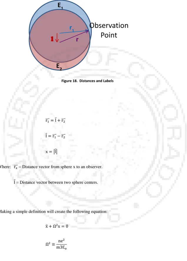
Figure 17. E-Field Spheres, Super-positioned ... 41
Figure 18. Distances and Labels ... 43
Figure 19. Surface Plasma Resonance... 44
Figure 20. Quadrant II Metamaterial ... 48
Figure 21. Thin wire metamaterial structure ... 51
Figure 22. Proto Circuit Board Machine ... 52
Figure 23. Quadrant II Metamaterial Model, Source = James Vedral of University of Colorado . 55
Figure 24. Quadrant II Metamaterial Model Results ... 56
Figure 25. Proposed SSRR Design... 59
Figure 26. Quadrant III Metamaterial Model, Source = James Vedral of University of Colorado 61
Figure 27. SSRR Model Results ... 62
Figure 28. Metamaterial Reciprocity Test Setup ... 64
Figure 29. Metamaterial Reciprocity, same polarization ... 66
Figure 30. Metamaterial Reciprocity, cross polarized ... 67
Figure 31. Patch Antenna Schematic ... 71
Figure 34. Patch, Ground Plane ... 72
Figure 35. Patch, Feed ... 72
Figure 36. 11 GHz Patch, S
11... 74
Figure 37. 11 GHz Patch, Impedance ... 75
Figure 38. 11 GHz Patch Antenna, E & H Plane Radiation Patterns ... 77
Figure 39. Metamaterial with Patch ... 80
Figure 40. Metamaterial with Patch ... 80
Figure 41. Normalized Meta-Antenna Patterns over 9.8-10.0 GHz ... 83
Figure 42. Normalized Meta-Antenna Patter over 11-12 GHz ... 84
Figure 43. Normalized Meta-Ant Best 3 ... 85
Figure 44. Normalized Meta-Ant Enhancement ... 85
Figure 45. Meta-Patch Gain Baseline Test Schematic ... 88
Figure 46. Meta-Patch Gain Test Schematic ... 88
Figure 47. Meta-Patch, Normalized E-Plane Pattern at 11.45 GHz ... 94
Figure 48. Patch Antenna, Normalized dB E-Plane Pattern at 11.45 GHz ... 95
Figure 49. Bi-Ridged Flared Horn Antenna, Normalized E-Plane Pattern at 11.45 GHz ... 96
Figure 50. Flared Waveguide Horn Antenna, Normalized E-Plane Pattern at 11.45 GHz ... 97
Figure 51. Meta-Antenna Reciprocity Test Setup ... 101
Figure 52. Meta-Antenna Reciprocity, Normalized dB E-Plane ... 103
Figure 53. Meta-Antenna Reciprocity, Normalized dB H-Plane ... 104
Figure 54. Meta-Lens Construction ... 105
Figure 55. Meta-Lens Pattern Test Setup ... 107
Figure 56. Double Beam Meta-Lens, 10.83 GHz ... 108
Figure 57. Double Beam Meta-Lens, 10.75 GHz ... 109
Figure 58. Meta-Lens Gain Test, Baseline Test Setup ... 111
Figure 59. Meta-Lens Gain Test Setup ... 111
Figure 60. Ray Trace Geometry ... 118
Figure 61. Maximum Δ Displacement vs. Angle of Incidence (rads), Source = Victor Gozhenko of
Univ. of Colorado ... 119
Figure 62. n > 0 Ray Trace ... 119
Figure 63. n < 0 Ray Trace ... 121
Figure 64. Material Properties Test Schematic, IR Sensor ... 127
Figure 65. IR Detector Material... 127
Figure 66. IR Material Properties Test ... 129
Figure 67. 17 GHz Material Displacement w/Meta ... 129
Figure 68. IR Material Properties Test ... 129
Figure 69. 17 GHz Material Displacement w/o Meta ... 129
Figure 70. 10.8 GHz Material Displacement w/Meta ... 130
Figure 71. 10.8 GHz Material Displacement w/o Meta ... 130
Figure 72. Optical Test Schematic ... 131
Figure 73. Microwave Material Properties Test Schematic ... 134
Figure 75. Right Handed Material Fresnel Coefficients, Scenarios 1-3 ... 162
Figure 76. Left Handed Material Fresnel Coefficients, Scenario 4 ... 176
Chapter 1. Introduction
1.1 Purpose and Chapter Descriptions
his thesis is a doctor of philosophy dissertation for the Electrical and Computer Engineering Department at the University of Colorado, directed by Dr. John Norgard and co-directed by Dr.‟s Hoyoung Song and Tolya Pinchuk. This dissertation will introduce numerous new areas of research within microwave metamaterials. Given the microwave focus, research was carried out in the macro-scale, or centimeter scale, and does not detail any research on the nanometer scale, which is so common within the metamaterials field.
Chapters one and two, and to some extent chapter three, provide information regarding literary searches. These chapters provide background information while describing the extent of my literary search relating to this dissertation topic. It clarifies what has been accomplished, or current areas of metamaterials research. Chapter three provides extensive detailed metamaterial theory. It is believed this background is required to better understand my work, assumptions, reasons for various research directions, and the like. Remaining chapters convey my new and unique work, which has transpired over numerous years at the University of Colorado, since Dr. Pinchuk first addicted me on the subject back in 2008. Appendix A simply reproduces collaborative work submitted for publishing and peer review, which has yet to be published. It is reproduced in unmodified form, and was submitted for publication in Physical Review B, in January 2011, and later submitted to the Journal of Applied Physics. Appendix B provides my metamaterial calculator Perl computer code. A new paper, based on my meta-lens work detailed here, is to soon be submitted for publishing within a physics journal, but it is a bit premature to include that work within this document, along with a National Science Foundation proposal recently submitted based on this related work.
1.2 What is a Metamaterial?
A definition of metamaterial is in order, as most works lack the definition or ill define the concept. A metamaterial is a composite material producing macro-scale permittivities, permeabilities, and resulting indices of refraction not found within its constituent materials. Note that my definition does not exclude positive or negative values for any of these material parameters: Permittivity, permeability, or index of refraction. The more commonly researched metamaterials are those with both negative permittivity and negative permeability, also called double negative materials, which can produce quite startling electromagnetic effects. Currently, most research involves man-made metamaterials. However, this metamaterials definition does not exclude naturally occurring composite materials from being a metamaterial with differing, from constituent components, electromagnetic properties on the macro-scale; as they are most likely certain to naturally exist in relative obscurity, or at least without the fanfare of man-made metamaterials. An example of an unintended man-man-made metamaterial would be microwave cooking oven doors, which should have a plasma resonance at some determinant frequency; though, most likely not improved directivity at 2.45 GHz where they operate in frequency (hopefully not so). As an interesting side note, it would be curious to model a microwave cooking oven door. Naturally occurring metals suspended within material would constitute a metamaterial, such as metal ions in sea water (though maybe only slightly „metamaterialish‟), or metal distributed within earth on a larger scale than the ore itself, chicken wire, metal fencing, etc.
„Left handed materials‟ and „metamaterials‟ are used interchangeably within numerous articles and texts. As will be discussed later, I claim left handed materials are a subset of metamaterials, as are right handed materials; both of which render the complete metamaterial set.
1.3 Some Metamaterial History
fraction over three decades later in 1999, Sir John B. Pendry used Veselago‟s work to develop new concepts, such as the thin wire model to obtain negative permittivity indices, as they should exhibit resonant frequency responses similar to plasma media[33]. Pendry also later described materials that could produce negative permeabilities, using split ring resonators (SRRs) acting like magnetic dipoles. In March 2000, David R. Smith and Sheldon Schultz used Pendry‟s work to create the first double negative metamaterial, within the microwave range of frequencies[29]. Since Smith et. al. had demonstrated the first double negative metamaterial, it was at this point in time a flurry of new research began to expand knowledge of these metamaterials. Though the flurry of new metamaterial research continues, relatively little has been explored since Veselago and Smith have essentially opened up three quarters of the electromagnetic materials space. Invisibility cloaks continue to be one of the most researched topics, regarding metamaterial implementations. In October 2006, David Smith et. al. demonstrated the first „invisibility cloak‟, within the microwave frequency range[34]. Since then, other uses have been theorized or produced in later years, which will be later explored within this thesis.
1.4 General Metamaterials Information
The vast majority of materials reside within quadrant one of the electromagnetic material space (see Figure 1). However, some natural materials do exist, under unique conditions, within the second and fourth quadrants. For example, a number of metals such as silver and gold reside within the second quadrant, within the ultraviolet frequency range. However, no natural material has been found within the third quadrant.
According to Wikipedia[4], materials residing within the second and fourth quadrants are opaque to electromagnetic radiation. This source also indicates all transparent media resides within the first quadrant of the electromagnetic material space, which shall be proved later. Wikipedia[4] also writes that Ɛ and µ do not have to be simultaneously negative to provide a negative index of refraction, which can be seen in Depine and Lakhtakia[14]. In essence, negative radical solutions for the index of refraction result if the permittivity and permeability are both less than zero. Some debate continues regarding whether or not it can be demonstrated that the negative radical is also forced if only one of these two parameters is less than
Quadrant III Ɛ < 0 and µ < 0
N < 0 Left handed materials.
No natural materials; man-made metamaterials only. Small freq. portions semi-transparent to EM radiation. E&M wave propagation with significant attenuation.
Quadrant I Ɛ > 0 and µ > 0
N > 0 Right handed materials. Almost all natural materials.
Large freq. portions transparent to EM radiation. E&M wave propagation.
Quadrant IV Ɛ > 0 and µ < 0 N > 0 or N < 0 ??? Left handed materials. ???
Very few natural materials at specific frequencies. Opaque to EM radiation (huge attenuation).
No wave propagation. Quadrant II
Ɛ < 0 and µ > 0 N > 0 or N < 0 ??? Left handed materials. ???
Very few natural materials at specific frequencies (e.g. metals at optical frequencies). Opaque to EM radiation (huge attenuation).
No wave propagation.
µ
Ɛ
Hoa and Mittra indicate wave transmission occurs only when both parameters have the same sign[26]. This means that transmission only occurs within quadrants I and III of the electromagnetic material space (see Figure 1). As to why this is so will be detailed later.
One point to keep in mind is that Ɛ and µ are the only relevant electromagnetic macro-scale material parameters used to describe electromagnetic wave interactions with a material. Though this interaction may become extremely complex for inhomogeneous materials, it does hold for homogeneous materials, or materials that are homogeneous to less than a single order approximation. This is one reason why metamaterial inclusions should be much less than the wavelength for which they work. The popular inclusion size appears to be less than an order of magnitude, or a factor of 0.1, of the wavelength for which it is to function, as macro scale approximations are much simplified.
An interface from a regular medium to a metamaterial medium does not imply that Snell‟s law provides a negative index of refraction. Also, metamaterial effects are not always the result of having negative values for both Ɛ and µ, as these parameters can have any number of values and mathematical signs. Rightfully so, the authors of [15] illuminate an obvious and most likely forgotten issue. The interesting portion of metamaterials is not the medium itself, but the resulting refraction on the interface between a regular material and a metamaterial, especially a left handed material.
Hapgood‟s article[17] points out some interesting artifacts of metamaterials. Living within a silvery bubble, anyone inside a visible spectrum metamaterial cloaking device would not be seen, nor would they be able to see outside their metamaterial bubble. However, the 2011 Third International Topical Meeting on Nanophotonics and Metamaterials indicated this is not so, and unidirectional effects could be seen1.
Another effect would be ripples within a pond of metamaterial might flow inward toward the site of impact with a rock[17]. Much like fish swimming above a metamaterial, I find this difficult to visualize. How would the ripples begin far away from the impact site, and then ripple toward the impact zone? I noticed the article used the subjunctive tense, with the word „might‟. In any event, this phenomenon and others yet to be realized, provide a tantalizing curiosity of the largely unexplored materials space.
A metamaterial obstacle to overcome is the absorption of radiation as it passes through a metamaterial; γ in Drude‟s formula. In order to experience a visible cloaking metamaterial properly, the radiation must pass through the material before it is significantly absorbed. This appears to be a substantial problem to overcome. Therefore, researchers strive to obtain metamaterials that are broader in bandwidth, as well as reduce absorption of the radiation it affects.
It should be noted that an electromagnetic wave undergoes a wavelength change when traveling from one index of refraction to another different index of refraction. As a side, and something to remember, this gives rise to dispersion in the visual light spectrum of different wavelengths. The frequency on both sides of the media must be the same, so time coincidence is maintained. However, due to the differing velocities, the wavelengths will be different[13].
Chapter 2. Metamaterial Artifacts and Curiosities
2.1 Proposed and Theorized Metamaterial Uses
y far, the most popular postulated use of metamaterials involves cloaking devices to make things invisible, particularly within the visual portion of the spectrum2. University of Maryland‟s Clark Labs was the first to manufacture and prove the concept within the infrared spectrum, on the nano-scale[23]. New successful strides toward visible spectrum invisibility cloaks occur almost monthly. Berkley has been one of the most successful entities broadening the bandwidth of their invisibility cloaks, again on the nano-scale within the infrared spectrum[6]. Recently, the University of California in Los Angles has successfully manufactured a cloaking device on the centimeter scale, measuring two feet long by four inches wide[17]. This scale is orders of magnitude larger than previous successes, but functions only within a portion of the microwave range.
The 3 March 2009 Science Daily article[16] reported a significant breakthrough, using metamaterial technology. Padilla et. al. controlled a wide range of teraHertz beam radiation using a metamaterial structure. This is significant in that it demonstrates an entirely new method of controlling radiation using a solid state, electronically fast, and wide bandwidth method. This may have significant implications for the traveling wave tube (TWT) and associated industries. This opens up modulation methods for the teraHertz range of radiation, which has historically not been possible on an electronically fast scale.
Hapgood[17] mentions identifying specific molecules using metamaterial enabled spectrometers. I assume this would be enabled via sub-wavelength optical resolution. Radiation shields for specific items were mentioned, such as performing surgery with a metamaterial scalpel while using MRI machine
2 Recently, more and more articles and texts have been loosely defining „invisibility‟ to include non-visible spectra as well, e.g., infrared and ultraviolet.
imaging. The metamaterial principles, not metamaterials themselves, could be used to manipulate other waves. Examples of this include controlling water waves from storms around oil rigs and tidal waves, or producing acoustic quiet spots within noisy environments.
The paper by Lindell et. al.[15] indicates that reverse Poynting vectors are already known to exist in some structures, prior to the metamaterials thrust. One such structure is the traveling wave tube (TWT) for certain frequencies. This is a result of a periodic structure within the TWT. Thus, one could argue that this structure, in itself, may be thought of as a metamaterial structure; even if it pre-existed Veselago‟s 1967 introduction of metamaterials.
A unique scenario of electromagnetic parameters provides a unique effect. If 1 = - 2 and µ1 = -µ2, then there will be no reflections, as I prove later in the Fresnel Coefficients Matrix chapter. If there are no reflected waves when the condition µ1 = -µ2 and Ɛ1 = -Ɛ2 is satisfied, this can be applied to make a simple matched focusing lens; i.e., the „perfect lens‟ (almost perfectly lossless). A lot of metamaterials research is dedicated to this „perfect lens‟, which will be later detailed further. I will soon explain how resolution beyond the diffraction limit is possible, as has already been demonstrated by Berkeley and The University of Toronto.
Veselago‟s paper[32] predicts right handed versus left handed electromagnetic wave propagation, reverse Doppler effects, reverse Cherenkov radiation, negative or positive permeabilities, negative or positive permittivities, negative radiation pressure (or positive tension), reverse bi-conical and bi-convex lens roles, negative Snell angles, and negative indices of refraction. We have only scratched the surface of material use possibilities. Three fourths of the entire electromagnetic material space has recently been opened. Who knows what will come of this new area? I‟ve detailed only recent tangible successes below, not theoretical or future possibilities. We have entered the era of metamaterials, nano-photonics, or plasmonics.
2.2 The Perfect Lens
The „perfect lens‟ (also known as „super lens‟) describes a Sir Pendry idea that a metamaterial can be manufactured which acts as a lens, with special properties to include no reflections and no theoretical resolution limit[28]. Refractive index variations allow traditional lenses to focus electromagnetic waves to a single point, but no smaller than a square wavelength. Unfortunately, evanescent waves decay too rapidly, and no traditional mechanism allows perfect phase reconstruction, even if the evanescent wave amplitudes were restored. Thus, the traditional diffraction limit is born. The maximum resolution within an image will not be less than one wavelength, regardless of lens imperfections and aperture size. Evanescent waves are those near field, non-propagating electromagnetic wave components.
Using double negative metamaterials, however, one can manufacture a lens unrestricted by the bounds of the diffraction limit, mainly because evanescent waves are reconstructed. Therefore, all source information is contained within the image created by this perfect lens. If the permittivity and permeability match that of the transmitting medium, but are negative in mathematical sign, then the impedance will be positive and perfectly matched, and thus no reflections will occur. The equation for the reflection coefficient solves to zero (0% reflection), while the equation for the transmission coefficient solves to one (100% transmission), see chapter 14. Moreover, the medium does not attenuate evanescent waves, and evanescent phase is not distorted. Actually, the evanescent waves are amplified via this medium transmission. One might hastily assume a conservation of energy violation, but no energy is transmitted via evanescent waves.
√ √
Given the amplification of evanescent waves, normal propagating and evanescent waves both contribute to image reconstruction. Discounting manufacturing limitations of the metamaterial lens, there is no theoretical image resolution limit. One last item to note is that this perfect lens is a planar slab of metamaterial, and no curved surfaces are required, given that electromagnetic waves bend toward the normal; i.e. no curvature is required, like that of optical glass lenses. Though not fully understood, Smith
et. al. indicate that these metamaterial slabs will not focus electromagnetic waves from infinity (assumed planar waves are referenced)[25]. This may simply state that the perfect lens cannot be located at infinity due to evanescent wave proximity concerns, as opposed to planar waves being focused by the perfect lens.
Just a note to indicate Dr. Pinchuk and I had difficulty solving for the no-reflection situation for the perfect lens situation. Therefore, it is left out of this thesis.
Within the same article, Pendry indicates that the γ = 0 approximation within the Drude formula is fine for numerous metals, specifically calling out silver, gold, and copper. He indicates that this is because these metals behave much like perfect plasmas.
The first perfect lens (resolution below the diffraction limit), at microwave frequencies, was demonstrated at the University of Toronto in 2004. In 2005, Zhang of Berkeley demonstrated the first optical perfect lens, with a resolution several times better than the best optical microscope. Though, Zhang enhanced evanescent modes via surface plasmon coupling, not negative indices of refraction.
2.3 Cloaking Success
As this is of obvious interest to many people, I will detail various successes in this regard, but note that cloaking breakthroughs occur often. Many other cloaking devices have been very successful. Given the sheer number of successes, only the first two breakthroughs are detailed.
The first cloaking device, resonant within the microwave frequency range, was developed at Duke University by Smith et. al. in 2006. It cloaked a copper cylinder at the resonant microwave frequency.
Figure 2. Duke Metamaterial, Source = Science Oct 2006
The University of Maryland‟s Clark School of Engineering claims to have created the world‟s first true invisibility cloak[23]. The cloaked object is only 10 nanometers wide, for a narrow frequency range, but proves the concept. The cloak is comprised of a two dimensional configuration of gold concentric rings, coated in polymethyl methacrylate (plastic). The entire configuration lies on a gold surface. This work was reported in New Scientist and in Discover Magazine‟s “Top 100 Science Stories of 2007”.
As written previously, a significant metamaterial issue to overcome is the lossy material problem. It would be amazing to design and manufacture an invisibility cloak, but it would not do much good if the invisibility cloak attenuated light so much as to appear as a dark cloud moving around. In [28], Smith et. al. indicate no material has demonstrated low loss in combination with a negative permittivity. However, numerous claims since then, to include the Nanometa 2011 conference in Seefeld Austria3, indicate that low loss double negative materials have been achieved.
2.4 Directive Emission Using Metamaterials
Enoch et. al.[27] demonstrated that emission within a metamaterial can be used to direct microwave energy. Their paper shows that emissions within close to zero, but positive, relative permittivity metamaterial slabs produce emissions close to the normal upon exiting the slab, even for very small incidence angles at the interface.
To demonstrate this effect, the authors modeled and manufactured a six layered metamaterial, with an additional ground plane. Their feed element was a monopole placed between the third and fourth layers. They measured the system‟s directivity as 372. It matched decently close to the model, which used the method of moments, thin wire approach. For their frequency, 14.65 GHz, their design approximates the plasma frequency using the Drude formula with the γ = 0 approximation. Their design also uses copper wire mesh on printed circuit boards, sandwiched between foam boards.
Another group, Li et. al.[10], used circular waveguides with a double layer metamaterial. They also experienced directive emission improvement. eff was designed using the γ = 0 Drude formula approximation. They indicated an 8.3 dBi improvement.
This work will later illustrate several new examples and methods of directive emission enhancement.
2.5 The Cherenkov Detector
Cherenkov radiation is radiation induced by charged particles moving through a medium, at speeds faster than the speed of light within that medium. Cherenkov radiation detection has a significant place within high energy physics, such as that used within particle accelerators. Antipov and Spentzouris envision using metamaterials to enhance Cherenkov radiation detection within particle accelerators[35]. Veselago‟s paper[32] predicts reverse Cherenkov radiation. Antipov and Spentzouris intend to use this phenomenon to collect this radiation in a cleaner environment, than traditional forward scattering. The radiation propagates in the opposite direction to accelerator particles and propagating waves. Thus, the double negative metamaterial should enjoy a cleaner environment in which to collect this radiation. They have produced the appropriate metamaterial, but have yet to perform the accelerator experiment.
2.6 Negative Radiation Pressure
During the 2011 Nanometa conference, Dr. Henri Lezec of The National Institute of Standards and Technology (NIST) provided a presentation experimentally demonstrating Veselago‟s predicted negative radiation pressure, or radiation tension4. He experimentally confirmed his results using both a blue and green 1 mW laser. His first experiment used an ultra-tiny left handed material cantilever within a scanning electron microscope. The right handed material exhibited a radiation pressure as expected, and the left handed material exhibited a radiation tension. Another experiment was later performed using an ultra-tiny
4 THU6s breakthrough 4 talk by Henri Lezec of NIST-MD, at Nanometa 2011, Third International Topical Meeting on Nanophotonics and Metamaterials, 3-6 January 2011 in Seefeld, Austria.
left handed material slab, within an evacuated chamber. This slab lifted up toward the laser, and the top of the housing, when the laser was turned on.
Dr. Lezec also briefly mentioned how the discrete photon momentum change occurs at the positive index of refraction to the negative index of refraction interface, via “Photon assisted reverse Doppler shift force and the Lorentz force”; all without violating conservation of energy or conservation of momentum.
Chapter 3. Metamaterial Theory
3.1 Introduction to Metamaterial Theory
or a better understanding of mechanisms behind these investigations, this chapter details the processes behind how metamaterials influence and manipulate electromagnetic fields. This chapter should assist the reader in better understanding efforts detailed within this work.
As the reader will see, material permittivity or permeability will be modified using inclusions. It will later be evident that these modifications of permittivity and permeability are accomplished without employing magnetic or ferrous materials. In reality most modifications are accomplished employing copper patterns.
3.2 Law of Refraction (Snell’s Law) and Refractive Index
Snell’s law gives us:( ) ( )
and
⁄
Where: Nx = Index of refraction, or refractive index, per subscript material.
ϴx = Angle of electromagnetic wave incidence, per subscript material.
c = Speed of electromagnetic wave propagation, within a vacuum.
vp = Speed of electromagnetic wave phase front, within material, not the speed of energy transfer.
ω = 2πf = Radian frequency.
k = Wave number.
f = Frequency.
λ = Wavelength.
The index of refraction can also be calculated via:
√
Where: N = Refractive index of material.
Ɛr = Relative permittivity of material.
µr = Relative permeability of material.
Lastly,
Where: = Group velocity, speed of energy transfer.
3.3 Index of Refraction’s Forced Radical Sign
all materials have a positive index of refraction. For centuries, scientists and engineers assumed the positive radical result. A negative radical does indeed result for the index of refraction, if Ɛr and µr are negative, as shown below for the purely real parameter case. This describes quadrant III of the electromagnetic material space, see Figure 1.
√
Where: N = Refractive index of material.
Ɛr = Relative permittivity of material.
µr = Relative permeability of material.
Now let‟s display the variable signs, explicitly, and solve for N again.
We know Ɛr < 0 and µr < 0, so we can rewrite this as:
√( ) ( )
√( )√( )√
√
√
As normally used for centuries from empirical results found in nature, a positive radical results for the index of refraction, if the Ɛr and µr components are both positive. This describes quadrant I of the electromagnetic material space, see Figure 1. However, what if one of the two electromagnetic material parameters is less than zero, while the other is positive? These two circumstances describe quadrants II and IV of the electromagnetic material space, see Figure 1. As you can see below, the index of refraction becomes purely imaginary, again for the purely real parameter case, and does not propagate or transfer energy.
√( )√
√
3.4 Snell’s Law with a Metamaterial Twist
Explanations regarding the physical effects of a negative index of refraction are sometimes difficult to imagine. Figure 5 illustrates the physical situation, which has been verified experimentally, and two new methods of measurement are presented later in this work.
Articles provide examples of how straight poles from air into a metamaterial with a negative index of refraction would appear to bend above the interface, as well as any fish swimming within this metamaterial would also appear to swim above this metamaterial[5, 6 part 1, 6 part 2, 17]. See Figure 4 for an illustration of fish swimming above a double negative material.
Figure 4. Fish in n<0 material, Source = Jason Valentine of Berkeley5
These phenomena are believed to be the result of „mental tricks‟, much like that of watching a fish swimming in water from a stream bank. To the shore observer, the fish appears to swim in a location where it is not actually located. Referring to Figure 5, the fish‟s location is along the n2 > 0 solid red line trace, but to the observer it‟s
located along the dashed black „ray
5 Use authorized 29 March 2011 by Sarah Yang, Office of Public Affairs, Berkeley University. Material1 Material2 ϴ2 Angle of refraction for n2 > 0 Line normal to interface ϴ2 Angle of refraction for n2 < 0
Figure 5. Illustration of Snell's Law with Negative Index of Refraction n1
trace of the incidental ray‟ since the observer‟s normal visual experiences usually never involve refraction. Therefore, a double negative material is theorized to produce like effects; poles bending back above the surface, and fish swimming above the interface surface. I continue to truly find it difficult to visualize this negative index effect, and wonder how it would truly appear to an observer, especially when a fish swimming above a metamaterial is also mentally non-intuitive. I anxiously await such a double negative metamaterial.
3.5 Permittivity
One of the many uses of metamaterials is to reduce a material’s plasmon frequency. Altering effective permittivity is one method used, as was used for the quadrant I and II metamaterial described within this thesis. This subsection describes the theory regarding how this is achieved.
( ) 6 7
Equation 1. Drude Formula.
And
Where: Ɛeff = Effective permittivity.
ω = Radian frequency.
ωp = Plasma frequency.
γ = Scattering rate.
Where: ωp = Plasma frequency.
neff = Effective electron density, of single electron.
e = Electron charge.
Ɛo = Permittivity of free space.
meff = Effective electron mass, of single electron.
Note that Ɛeff is negative (metamaterial criteria via some articles) when ω < ωp . Though this may be a poor approximation, a few articles[10, 27, 28, 29] took γ = 0 for long wavelengths. Given this approximation, the Drude formula becomes:
( )
This γ = 0 approximation of the Drude formula did appear to work for Li et. al. in their antenna array work [10]. They actually manufactured the modeled array, and both the model and manufactured antenna array achieved fairly close results. For the metamaterials designed and manufactured within this thesis, the γ = 0 Drude formula approximation was also successfully used.
3.6 Split Ring Resonators
Split ring resonators (SRRs), and variants thereof, have played a significant role in producing double negative materials. Sir Pendry was the first to predict their potential use for obtaining negative permeabilities. David Smith was the first to actually design and manufacture a double negative material
using split ring resonators. Smith et. al.[29] did derive an equation for their specific split ring resonator‟s effective permeability, µeff.
Where: µeff = Effective permeability of material.
F = Fractional area of unit cell occupied by the interior of the split ring.
ω = Radian frequency.
ωo = Technically unanswered, but assumed free space radian frequency.
Γ = Dissipation factor.
Smith et. al.‟s article goes further providing another approximation for the plasma frequency. It does not provide the derivation, but gives the approximation as:
√ (for high conductivity values)
Where: ωp = Radian frequency.
d = technically unanswered, but may be trace diameter.
L = Self-inductance per unit length.
⁄ Free space permittivity.
3.7 Narrow Frequency Bandwidths
One significant item to note is the narrow band characteristics of metamaterial enhanced items. Li et. al.[10] illustrate this using two graphs within their paper. The first graph illustrates antenna gain versus
mesh spacing. This demonstrates just how narrowband the metamaterial functional frequency is, which is due solely to the wire mesh spacing. The 3 dB mesh spacing is ≈ 3 mm. The second graph plots antenna gain versus frequency. The 3 dB frequency bandwidth is ≈ 4.2% (500 MHz at 12 GHz). Again this illustrates just how narrowband the metamaterial usable frequency is. It appears that new approaches will be required to overcome the inherent narrow frequency bandwidth issue. Of course, narrow frequency bandwidths can be very advantageous, depending upon the application.
Indeed this appears to be one major issue to overcome for metamaterials. A lot of energy and work is focused on making wider bandwidth metamaterials; especially with respect to optical frequencies to manufacture optical cloaking devices. Research, thus far, indicates that not much progress has been made in this regard. The best success appears to be from Berkley‟s work on wire meshes, which obtains a negative refractive index between 1.5 µm to 1.8 µm, which is within the infrared spectrum[6]. However, recently Vladimir Shalaev of Purdue University claims to have developed a theoretical concept that allows much wider bandwidths for double negative materials[35], as described at the Nanometa 2011 conference6.
3.8 Plasma Frequency
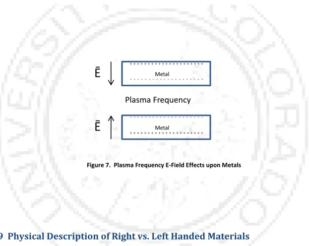
The plasma frequency (also known as the plasmon frequency) definition pertains to free electrons within metals, not the traditionally thought of ionized gas (i.e., plasma). Alternating electric fields, via the electromagnetic force, compel electrons to switch from side to side, almost instantaneously within metals, as illustrated in Figure 6. When alternating electric fields begin to oscillate fast enough, electron mass momentum issues begin to have affect. Normally these frequencies occur around ultra violet frequencies. The frequency at which electrons oscillate at the same frequency, but opposite to normally expected charge
repulsion, is called the plasma frequency, ωp, also known as the plasmon frequency. This condition is illustrated in Figure 7.
6 Nanometa 2011, Third International Topical Meeting on Nanophotonics and Metamaterials, 3-6 January 2011 in Seefeld, Austria.
3.9 Physical Description of Right vs. Left Handed Materials
There are actually two solutions to Snell‟s equation; a positive radical result, and a negative one. Traditionally, the positive radical is used, as it matches the observable naturally existing materials, with empirical perfection. The normal equation modeled solution is illustrated below. Note that right handed materials describe materials normally found in nature, and left handed materials are not thought of as existing in nature; though, I would argue double negative metamaterials probably do exist in relative obscurity. Both are subsets of metamaterials (composite materials), and furthermore, comprise the entire
Ē
+ + + + + + + + + + + + + + + + + + + + + - - -Ē
+ + + + + + + + + + + + + + + + + + + + + - - -Low Frequency Effects
Metal Metal
Ē
+ + + + + + + + + + + + + + + + + + + + + - - -Ē
+ + + + + + + + + + + + + + + + + + + + + - - -Plasma Frequency
Effects
Metal MetalFigure 6. Low Frequency E-Field Effects upon Metals
√ (Snell‟s Law)
Where: N = Refractive index of material.
Ɛr = Relative permittivity of material.
µr = Relative permeability of material.
⃑ ⃑⃑ ⃑⃑ (Energy flux, or Poynting vector)
Where: ⃑ = Poynting vector.
⃑⃑ = Electric field vector.
⃑⃑ = Magnetic field vector.
The Poynting vector, , and the wave vector, ⃑⃑ , are right handed if Ɛr > 0 and µr > 0. The wave vector, ⃑⃑ , is left handed and the Poynting vector, , is right handed if Ɛr < 0 and µr < 0. By right and left handed, I refer to the normal three finger position representing directions for the traditional power transfer (thumb), the electric field (index finger), and the magnetic field (middle finger). Figure 8 illustrates the overall results of the various vectors within various index of refraction materials. I show later why some vectors reverse direction. One thing to note is the Poynting vector, or direction of energy movement, continues in the same direction across media boundaries, irrespective of the K vector and index of refraction sign. This is a point of consequence for conservation of energy.
3.10 Proof of Snell’s Law Radical Sign Result
Again, the „choice‟ of the radical sign result for the index of refraction is really forced, depending upon the signs of the medium‟s permittivity and permeability. The index of refraction is positive for positive permittivity and positive permeability, which produces right handed materials. The index of refraction is negative for both negative permittivity and negative permeability, which produces left handed materials.
Sir Pendry indicates a mix of positive and negative permittivity and permeability also produces left handed materials[18]. Thus, according to Pendry[18], the only right handed quadrant of the electromagnetic material space is quadrant I; see Figure 1. However, this continues to be debated for quadrants II and IV, even within our physics team. I will provide an example. Sir Pendry, a non-disputed and knighted innovator and leader within the metamaterials industry, indicates quadrants II and IV provide left-handed materials, or materials with indices less than zero[18]. Why then does the iconic Handbook of
Optical Constants of Solids7 continue to be valid, before and after metamaterial mania, even for those Where: N = Index of refraction.
K = Wave vector, or K vector. Vphase = Phase velocity vector.
Vgroup = Group velocity vector.
S = Poynting vector, or S vector.
K S Vphase Vgroup
N > 0
K S Vphase VgroupN < 0
K S Vphase VgroupN > 0
relatively few materials exhibiting right-handed material properties within quadrants II and IV, such as gold and silver at specific frequencies?
I attempt to show, more heuristically, why the corresponding radical signs result for a double negative, or left handed, material. For this effort, the scenario uses a region that is charge free with linear isotropic media. Therefore the following relationships hold true:
⃑⃑ ⃑⃑
⃑⃑ ⃑⃑
⃑⃑
Where: ρ = Volume charge density.
⃑⃑ = Electric flux density vector.
Relative permittivity, or dielectric constant, of medium.
⁄ Free space permittivity.
⃑⃑ = Electric field vector.
⃑⃑ = Magnetic flux density vector.
Relative permeability of medium.
⃑⃑ = Magnetic field vector.
= Current density vector.
= Conductivity of the medium.
The point form of Maxwell‟s free space equations:
⃑⃑ ⃑⃑ ( )
⃑⃑ ⃑⃑
⃑⃑ ( )
⃑⃑
With the original assumptions of the region noted above,
and time dependence of for both ⃑ and ⃑⃑ , two of Maxwell‟s free space equations become:
⃑⃑ ⃑⃑ ⃑⃑ ⃑⃑ and ⃑⃑ ⃑⃑⃑ ⃑⃑ ⃑⃑ ⃑⃑ ⃑⃑ E H K & S Right Handed Orientation
⃑ ⃑⃑ ⃑⃑
Using the right hand rule for cross product, this time, yields the electromagnetic right hand rule for wave propagation, as shown in Figure 9. This information and orientation is well known and understood. Keep in mind that the right hand rule for mathematical cross product is defined with the right hand and does not change, regardless of disparate physics definitions such as left or right handed electromagnetic vector orientations.
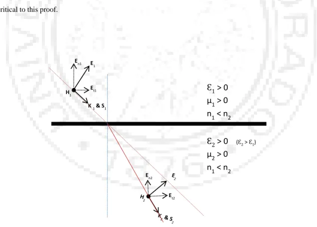
Now if the scenario uses negative values for permittivity and permeability, then things change with respect to orientation. This will be shown using well known and understood electromagnetic boundary conditions. I will continue using the same region assumptions and relationships defined in the beginning. I will use Figure 10 and Figure 11 to illustrate electromagnetic field orientations, which is critical to this proof.
Figure 10. Wave Orientation for N > 0 En1 H1 K 1 & S1 Et1 E1 En2 Et2
> 0
µ
1> 0
n
1< n
2 2> 0
( 2 > 1)µ
2> 0
n
1< n
2Figure 11. Wave Orientation for N < 0
Well understood electromagnetic boundary conditions dictate that tangential electric field components, relative to the interface, do not change from the passage of one material into the next. It is usually stated that the electric field‟s tangential component is continuous across the boundary. As well, this holds for normal magnetic field components, for current free conditions, again relative to the interface. Proofs for electromagnetic boundary conditions may be found in [19, 20, and 21].
Boundary conditions:
Et1 = Et2
r1En1 = r2En2
Ht1 = Ht2 (Current free conditions)
En1 H1 K1 & S1 Et1 E1
> 0
µ
1> 0
n
2< n
1n
2< 0
2< 0
µ
2< 0
n
2< n
1n
2< 0
En2 Et2Critical to note for this proof are a few things. Please refer to Figure 10 and Figure 11. The only component that changes is the normal component of the electric field. The tangential component of the electric field does not change, due to well understood boundary conditions. As for the magnetic field, the orientation chosen has the entire magnetic field oriented in the tangential direction, with respect to the interface. Thus, the magnetic field is continuous across the boundary, assuming current free conditions. Again, this is via well understood boundary conditions. There is no normal magnetic field component, which would have changed across the interface.
The same analogous argument can be made when the entire electric field component is tangential to the interface. In this case, the tangential magnetic component is continuous across the interface boundary. The normal component of the magnetic field is the only component that changes, and does so in the inverse direction just like the normal component of the electric field in the original scenario.
Using the same equations in the beginning of this proof, but now for Ɛr < 0 and µr < 0, we obtain:
⃑⃑ ⃑⃑⃑ | | ⃑⃑
⃑⃑ ⃑⃑ | | ⃑⃑
⃑ ⃑⃑ ⃑⃑
Using the right hand rule for mathematical cross product, one can now understand the Figure 12 results, and thus, why ⃑⃑ alters direction.
E H S Left Handed Orientation K
3.11 Bulk Plasma Frequency
Refer to the Plasma Frequency subsection of the Metamaterial Theorychapter, for a higher level description of plasma frequency. That subsection should assist in understanding this more detailed subsection. As the reader goes through this derivation, it will become evident that this is a resonant effect if either permittivity or permeability is less than zero
An electric field, ⃑ field, surrounding bulk metal produces a force upon the metal‟s electrons, since they have charge. Figure 13 displays the configuration of bulk metal electrons within the presence of an electric field.
For ease of understanding, the single dimensional electron movement case will be detailed. From general Newtonian Physics:
⃑ ⃑ ( ̈) ̂
Equation 2. Newton's 2nd Law
Where: ⃑ = Force vector.
m = Average mass of electrons.
⃑ = Acceleration of electrons.
̂ = Unit direction of accelerated electrons.
x = Average position of electrons.
̈ = Double derivative of average electron positions.
Bulk
Metal
- - - - - - - - - - - - - - - - - - - - + + + + + + + + + + + + + + + + + + + +E
externalX direction
EinternalAlso:
⃑ ⃑⃑
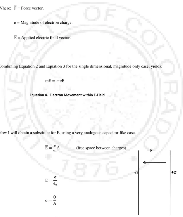
Equation 3. Force on Electron within an Electric Field
Where: ⃑ = Force vector.
e = Magnitude of electron charge.
⃑⃑ = Applied electric field vector.
Combining Equation 2 and Equation 3 for the single dimensional, magnitude only case, yields:
̈
Equation 4. Electron Movement within E-Field
Now I will obtain a substitute for E, using a very analogous capacitor-like case.
⃑⃑ ̂ (free space between charges)
E
+σ
-σ
Equation 5. Modified Newton's 2nd Law & Electric Field Force
Where: ⃑⃑ = Applied electric field vector.
ζ = Surface charge density.
⁄ Free space permittivity.
̂ = Normal vector.
= Applied electric field magnitude.
Q = Charge.
A = Area containing charges.
ρ = Volume charge density.
V = Volume containing charges.
x = Length in x-dimension, or x position, since zero-based.
n = Electron density.
Combining Equation 4 and Equation 5 yields:
̈
̈
̈
Using the standard mathematical differential equation solution provides:
Where: x = Position. ω = 2πf = Radian frequency. t = Time. Thus,
(bulk plasma frequency)
(bulk plasma frequency for SI units)
The plasma frequency, ωp, is the natural resonance of the material to an applied electric field. This kind of excitation was solved for, and is applied to, bulk metal materials. Therefore, ωp is often referred to as the „bulk plasma frequency‟.
To take things a bit further and find the energy and plasma wavelength for a couple metals:
Where:
h = Planck‟s constant, 6.625 x 10⁻³⁴ Joule-Seconds.
ωp = Plasma frequency.
For the metals of gold and silver, the energy is about 9.1 eV (electron Volts). This corresponds to plasma frequencies within the ultra violet range (λp (Au) ≈ 180 nm, λp (Ag) ≈ 410 nm).
Figure 15. Effective Permittivity vs. Energy
Most metals have an electron density on the order of n ≈ 1023/cm2. Thus, ωp is usually within the ultra violet region of the „visible‟ spectrum. It is usually advantageous to lower this frequency, especially when invisibility cloaks are of interest. Given the equation for bulk plasma frequency, there is really only one
I{Є
eff}
Re{Є
eff}
Transparent
Opaque
Є
effEnergy (ħω)
Metal with large n
Dielectric with low n
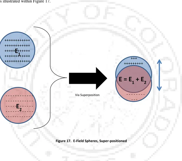
parameter we can change to lower ωp. This may not be readily apparent since 4, π, e, and m are all constants. That only leaves the electron density, n, which also appears to be a constant. n really is a constant for homogeneous materials, but we can indeed modify this number, within reason. In order to lower ωp, we need to lower n. Engineers lower the macro-scale value of n by integrating sub-wavelength inclusions having much lower values of n. Dielectrics have been used to do this. Thus, the overall macro-scale electromagnetic wave interaction is with an overall lower value for n. This is the basic premise behind metamaterials with lower relative permittivities, which provide composites with overall lower effective values of n.
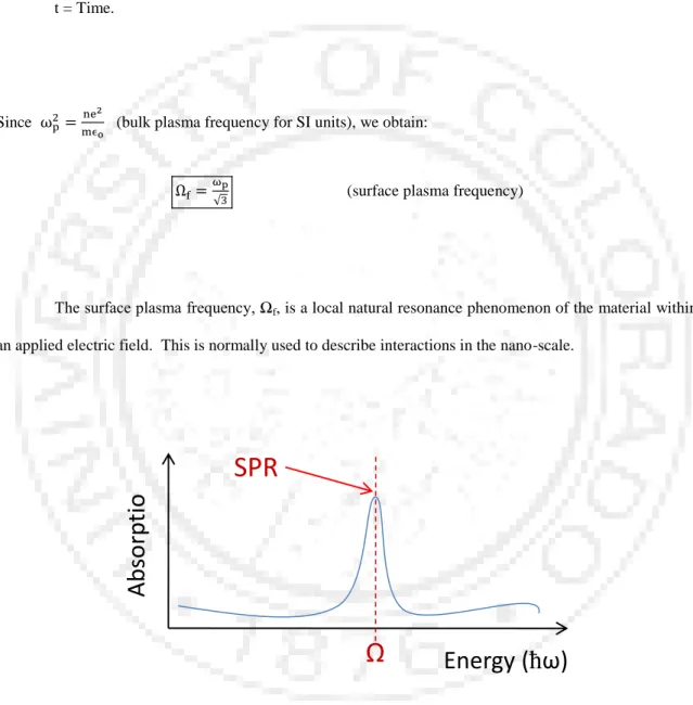
3.12 Surface Plasma Resonance
Surface plasma resonance (SPR) is very similar to bulk plasma frequency, or resonance. This is a local phenomenon and is more used on the nano-scale, than the bulk plasma frequency. As the reader goes through this derivation, it will become evident that this too is a resonant effect if either permittivity or permeability is less than zero. SPR is acquired via a different, but similar, method. The proof begins in the same manner as that for bulk plasma resonance, again using a single dimension for electron movement.
⃑ ⃑ ( ̈) ̂
Equation 6. Newton's 2nd Law
Where: ⃑ = Force vector.
m = Average mass of electrons.
⃑ = Acceleration of electrons.
̂ = Unit direction of accelerated electrons.
̈ = Double derivative of average electron positions.
Also:
⃑ ⃑⃑
Equation 7. Force on Electron within an Electric Field
Where: ⃑ = Force vector.
e = Magnitude of electron charge.
⃑⃑ = Applied electric field vector.
Combining Equation 6 and Equation 7 for the single dimensional, magnitude only case, yields:
̈
Equation 8. Electron Movement within E-Field.
Now Gauss‟ Law is used to obtain the electric field intensity. Gauss‟ Law dictates that the charge enclosed by a surface is equal to the electric flux density vector integrated over the differential surface vector.
∯ ⃑⃑ (Gauss‟ Law)
∯ ⃑⃑
Where: Qenc = Q = Charge enclosed by a surface.
⃑⃑ = Electric flux density vector.
= Differential surface element vector.
⁄ Free space permittivity.
⃑⃑ = Applied electric field vector.
For a spherical surface, the equation now becomes:
Where: r = Radius of spherical surface enclosing charge.
E = Electric field intensity.
If we now expand out Q using volume charge density and the volume of a sphere, we obtain:
(simplified)
(since ρv = ne)