INTERNATIONAL DESIGN CONFERENCE - DESIGN 2016 Dubrovnik - Croatia, May 16 - 19, 2016.
ASSESSMENT OF SIMULATION READY CAD
MODELS IN A SET BASED CONCURRENT
ENGINEERING CONTEXT
T. Heikkinen, J. Johansson and F. Elgh
Keywords: automated FEA, technology transfer, simulation ready CAD models, set-based concurrent engineering
1. Introduction
The use of product platforms has been acknowledge as a strategic enabler for mass customisation. There are many examples of successful implementation of a platform strategy based on a modular product architecture among OEMs. However, the adoption of such a strategy does not seem to be very common among sub-suppliers working in an ETO-oriented business environment where individual solutions are developed for each customer. The specific solution can be based on shared concepts, however, these concepts are more or less implicit and include other means than pre-defined modules. The development projects are executed in close collaboration with the customers. They can run for years and changes in the requirement-specification are frequently faced. Even though one specific solution is developed, the final production quantity is determined by the need of the customer. For companies working in such an ETO business model there is a need of another kind of platform model that supports customisation and easy adaptation to fluctuating requirements during the course of a development project [Andrè et al. 2014]. This can be achieved by acknowledging change as a normal condition and developing means to efficiently re-design and assess the impact of changes by adopting a set-based concurrent engineering approach in product development (PD). Set-based concurrent engineering is based on the development of many solutions or a design space for each domain [Ward et al. 1995], [Sobek et al. 1999]. The intersection of the domains is a feasible set and as the requirement specification evolves and individual requirements change, different feasible sets will be valid. In addition, the negative effects of a change can be assessed and discussed with the customer for agreement on future action. The principle seems promising, but how this could be realised is not, however, evident.
For sub-suppliers it becomes more and more important to proactively develop new technology to be a competitive partner in joint development initiatives. In some cases, the sub-supplier takes full responsibility for creating a solution for a sub-system in accordance to the functional needs defined by the OEM. The OEM expects to be presented with new and better solutions than existing that will give them a competitive edge. The sub-supplier can, by the development of new technology, stay ahead of the competitors by marketing activities and gain economy by scale using the technology in different solutions for different customers. Technology development (TD) and PD are both essential for the long term prosperity of companies within the manufacturing industry. Separation of the two has a positive effect on individual process efficiency but at the same time creates an integration issue [Nobelius 2002]. New technology can come in many forms, as described by Högman [2011]; it can be anything from “knowledge, skills and artefacts” with the intention to facilitate product development.
This paper presents the assessment of a method to automate Finite Element Analysis (FEA). The method has been tested at a case-company to support the transfer between TD and PD with respect to new product-artefacts in the form of CAD-models. The models are defined and used by the FEA-specialists in TD and the transfer of the ability to perform simulations to PD is then accomplished by enriching the models with additional information for their use in PD. This tool will act as one means that facilitates the company to adopt a set-based concurrent engineering approach. Effects of which hopefully increases safety of the product and at the same time reduces the total lead-time within the PD phase. It was developed at a company specialised in car roof racks and assessed with respect to its industrial need, scientific novelty, and further work required.
2. Research method
The overall research approach used in this work is based on the one suggested by Blessing and Chakrabarti [2009]. The work is part of a three-year long research project, called ChaSE (Challenge Fluctuating and Conflicting Requirements by Set‐Based Engineering), in close collaboration with four companies where joint case-studie activities are combined. Its main objective is “A novel method to develop and describe adaptive technology solutions with an ability to manage changing and conflicting requirements in the development of customised products.” The project deploys a spiral model, where theoretical and practical insights drive methods and models development. This work reports the findings and the development of a support that will enable one of the case-companies to manage changes in requirements and geometrical interfaces. This corresponds to the work package Industrial application part 2 (Figure 1) where prescriptive methods are implemented in demonstrators including improvements of the principle methods as well as the assessment of their applicability and efficiency.
Figure 1. Research method This was established by:
Exploring the proposed system and spending time at the company (once a week over a period of two months) to get a detailed and practical understanding of the reasons for its purpose and current state.
Conduct a literature research aiming at getting an understanding of similar systems already presented.
Conduct a survey to probe the industrial need.
The literature research was focused on the current automation systems involved with FEA. To find related literature the Scopus database was used to search for the following key words: automation, finite element analysis, FEA, CAD, knowledge based engineering, KBE, structured mesh, and technology transfer. The search resulted in 110 articles which were first screened with respect to the title, followed
by another screening session of the abstracts. After screening a total of 32 articles were considered interesting and 16 were available for full-text download. While reading these articles a number of related documents were also found resulting in 28 articles fully or partially read.
For the survey a sample was selected which represented as many affected areas of the organisation as possible. The sample finally consisted of employees with titles ranging from directors, project leaders, chief engineers and computational engineers. The system was presented to the group whilst encouraging comments, hoping to trigger discussions, as well as using questionnaires for individual feedback. The results are presented below (sections 3-5) and discussed in section 6 along conclusions drawn.
3. Related work
There are a number of similar systems presented in the literature. Research within especially the field of Knowledge Based Engineering (KBE) have come up with similar script and feature based systems as presented here. La Rocca and Van Tooren [2007] presents a KBE system where the FE-modelling system main-frame is a python application, detailed in [Nawijn et al. 2006] called PYCOCO. Instead of an entire template pre-processing script, which is used in the proposed system, there is a core library generating the pre-processing commands directly via a “pseudo-socket” file, function by function. Also the models are generated with high level primitives which are represented in XML files, capable of representing geometry along with properties and rules. The added information can be used to e.g. solve mesh segmentation issues.
Johansson [2008] presents a KBE system for manufacturability analysis using knowledge objects. Much like the system presented here an object-oriented approach is used.
Haque [2012] also presents a KBE system (Common Computational Model), he emphasises the importance of using one system main frame capable of performing as many tasks as possible. He claims it has been successfully implemented using the adaptive modelling language where fully integrated modelling of both CAD geometry and FE-models are possible. In [Dolšak and Novak 2011] the authors are critical to the use of knowledge based systems for fully automating the processes involved with FEA. They instead present a rule-based system for consulting users through the development of FEA.
Figure 2. Information loss, adapted from [Nawijn et al. 2006]
It has been pointed out by several authors that the most difficult part with automating FEA is the preparation of FE-models. One of the major contributors to this is the loss of information when moving
between the different processes, as depicted nicely by [Nawijn et al. 2006], see Figure 2. The information loss between the CAD and pre-processor is due to the restrictions in the neutral CAD-file formats used to transfer the models to the pre-processors. Capturing and storing the otherwise lost information, necessary to idealise a FE-model, is one of the main differences between the systems found in literature. Sun et al. [2010] introduced an ontology based approach modelled in the web ontology language (OWL). Gujarathi and Ma [2011] proposed a so called common data model (CDM) with fully parametrical modelling. In [Nawijn et al. 2006], a so called FEM-table is presented which is modelled in extensible mark-up language (XML) files.
One way of eliminating the limitations with neutral CAD-files is by merging the pre-processor into the CAD-environment. Chiciudean and Cooper [2010] discusses and implements this approach on the PYCOCO system. Also Chapman and Pinfold [2001] and Haque [2012] integrate the two.
4. Case study
The studied company develops and manufactures products that support an active life style. Some of the products are transport centred, e.g. roof boxes, and bike carriers. It makes roof racks for cars an important product for the company which also has been the target for this case study. Both safety and geometrical requirements are put on the product, since it has to be tightly mounted on the car roof so that it does not fall off in case of a crash, even if loaded with several bicycles or a heavy roof box. Still the car body must not be damaged, buckled or scratched, when mounting the rack. These two strict and contradicting requirements set a very tight design space and it is hence necessary to assess each new product variant through testing. Since the company policy is to provide roof racks for 95% of all car models worldwide the testing cost is extensive, which calls for virtual testing. One problem with virtual testing through FEM-simulations in this particular case is the extremely short project lead-time (some few weeks from a car entering the market to launching the roof rack production). This is why the company decided to examine how to automate the virtual testing process, a task that was adopted as this case study in the ChaSE research project.
The system employing the underlying method which has been developed is shortly described here and discussed further below. For a more detailed description see [Johansson 2014]. It is an automation task of established methods and processes which are performed in Solidworks (CAD-software), Ansa (pre-processor) and LS-Dyna (post-(pre-processor). The proposed system main-frame is built as an add-in to Solidworks with Visual Studios using the Visual Basic (.NET) programming language. Communication to users is done with a specific feature-name convention and custom macro-features which are translated to the pre- and post-processors through alteration of template scripts. A neutral CAD-file is then exported and used by the scripts to realise the Finite Element (FE) model.
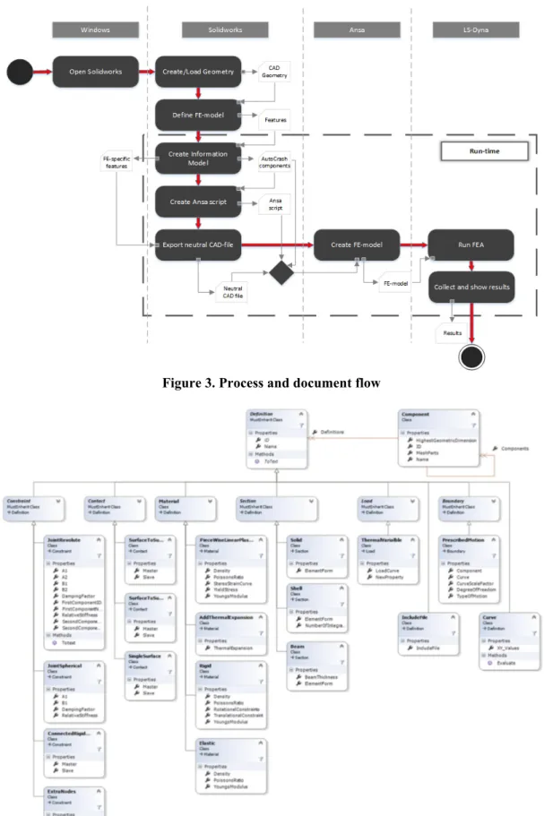
An overview of the corresponding processes and information flow can be seen in Figure 3. The information model used to represent the FE-model can also be seen below, Figure 4. The differences from a conventional way of working is that the FE-model is defined within the CAD software and automatically idealised in the pre-processor. To do this the FE-specifics are saved in an object model as shown in the class-diagram in Figure 4. The idea is that a “Component” is made up of MeshParts and Definitions. MeshParts represent the features requiring meshing and Definitions the other FE-model specifics such as contacts, loads, materials etc. Some of the process steps as seen in Figure 3 are now detailed further.
Figure 3. Process and document flow
4.1 Define FE-model
As mentioned above, there is a feature-naming convention and custom macro-features used to idealise the CAD-model as a FE-model, using the information model in Figure 4. The naming can be done both manually and partially with the help of an interface in the form of Solidworks own property-managers, retrieved through a custom command-manager (Figure 5). FE-model definitions, such as contacts, materials, loads etc. are stored in the macro-features, also retrieved through the custom command manager with associated property-manager.
Figure 5. Solidworks environment (Property and Command Manager)
FE-models are concerned with a different agenda, for this reason modification of the CAD-models is usually required. Removing small radii and aesthetic features or adding points and axes to enable efficient and trustworthy FEA with for example structured meshes. This can be done by creating new features, constrained to the base geometry, and naming or associating these with macro-features accordingly. An example can be seen below. In addition to meshing characterisation as seen below also load cases and component interactions can be addressed in the same manner. Since the features are stored in the CAD-files they will be checked into the PDM-system ready to be used in any assembly to generate FE-models.
Figure 6. Solving CAD-model modification issues 4.2 Create information model
Once the model has been defined the user can elect to create the FE-model. The add-in searches through the feature-tree and saves instances of the corresponding Information model classes (Figure 4)
depending on the names and infromation in the macro-features. All features which are not recognised are suppressed leaving only the FE-model specific features.
4.3 Create Ansa-script and Export neutral CAD-file
With all the MeshParts and Definitions retrieved a neutral representation of the remaining geometry can be exported and customised scripts created with the Ansa templates. The Ansa templates require:
A material data file. Neutral CAD-file.
Separate meshing parameter and quality specifications for shell and volume meshes. Paths for process log-file and final FE-model output (keyword-file).
The template Ansa scripts are tagged with specific names so the main-frame can input the corresponding information at the right position. Events which are required for each instance of a class are also enabled with specific names. In other words, looping is enabled.
4.4 Limitations The major ones are:
Feature names are lost when exporting the neutral cad files. This causes issues when for example parts have the same names which can cause rotational meshes to rotate around the wrong axis. Only material and revolute joint (constraint) definitions have been fully implemented.
Needs to be a one-component subassembly.
Only one mesh-part per component, i.e. cannot split components into several different meshes.
5. Results
Results from the presentation triggered several discussions. First of all the possible difficulties defining a final mesh within the CAD software was discussed. Usually the engineer spends hours removing fillets and entire sections of parts. Some refining before running the FE-analysis might therefore be necessary. This led to discussions regarding hybrid systems with respect to automatically meshing some parts and others manually. Also the possibility of pre-meshing some parts was brought up. Secondly the issues with surface contact was discussed, increasing the significance of solid meshes especially for the implicit solvers.
As for the questionnaire results, they have been translated from Swedish to English and are partially shown in Table 1. To summarise, all participants saw a potential use for the system at the company. Positive comments with respect to the potential time and safety improvements were given. One went so far as to say it was a requirement to be able to meet the deadlines in the future. However a big scepticism was emphasised on the lack of detailed information regarding the implementation and maintenance required. As well as risks related to losing control by putting too much trust in the system.
Most participants saw the responsibilities for the CAD-models to fully lie with the designers themselves, FE-models with the simulation-engineers and the connecting subsystem with the researchers.
Potential drawbacks given were; the amount of time required to formalise the methods to automation standards, loss of control with respect to quality of results, maintenance and development might require large amount of time.
Further work suggestions involved starting to run the simulations because that is when issues appear, improve user-friendliness when defining the FE-models and provide proper instructions, have periodic follow ups between researchers and company personal and finally a warning not to underestimate the complexity.
Table 1. Questionnaire results
Questions Answers
What do you think about
the system as a whole? company* is required to internally start working with method development at a “Good: with connections between Solidworks and Ansa. (In the future *case-whole new level.” “Looks very promising” “Good. Gives more security to
upcoming solutions/kit.” “Exciting, automation can increase the availability and amount of simulations” “Good”
Do you see any potential use of such a system at
your company?
“Yes” “Yes. I see a potential to reassure the development of new kits with crash-simulations of each unique solution.” “Yes, for kit development. We always have
an uncertainty when new kits are developed. Do not know if they are safe enough” “Big potential! Our roof-rack systems with kit-adaptions to each
car-model requires an automated FEA-process. If not: we get resource issues.” Who do you think should
be responsible for a) CAD-models, b)
FE-models, and c) subsystem?
a) “Each CAD-designer takes responsibility that the models are OK with respect to the simulation requirements” modellers + ChaSE (researchers)”
“CAD-designers of roof-racks”
b) “Simulation department” “Simulation department or educated CAD-modellers who fit the role” “Simulation department in the future, researchers from now and
3 years forward” “Simulation department and ChaSE (researchers)” c) “Research group” “Not sure how it looks in the future but researcher as of
now” “Do not know” What do you see as
potential drawbacks of the system?
“Method-development takes time! It is however important to further improve the internal processes to improve the enterprise.” “Can be hard to know whether the results accurately depict reality” “1) The step between CAD and FEA because of the big knowledge gap 2) Unfamiliarity to decipher results. Risk that the wrong
settings are used and gives good results which are believed to be true without critically assessing them.” “Complex system, risks are that we have to put a lot of time on maintenance and development. Such as when there are software updates.” What do you think could
be improved? “Do not know. Have not seen the entire system yet.” “CAD-models need to be better prepared in Solidworks for FEA” Do you think the
drawbacks overweigh the cost associated with implementation and maintenance of the
system?
“Do not know, what are the costs?” “Yes, lose a lot of crash-testing with respect to reference-cars. Not as risky to release bad solutions to the market” “Yes. Can show the customers to increase understanding” “Yes, from what I know now”
Do you see any areas which need to be further
investigated?
“Connections between FE-model in Ansa and analysis in LS-Dyna” “Mesh, user-friendliness information to CAD-modellers.” “Need more details to be able to
specify” What do you think is the
next step in the project? “Run the analyses. Its only then that the problems reveal themselves.” “Plan for continuous meetings between the researchers and company” Other comments? “Do not underestimate the results” “Good if everything is integrated within
Solidworks.”
6. Discussion
6.1 Industrial need
It is clear from the presentation and questionnaire session at the case-company that the system presented here is needed. Being able to assess new CAD-model technologies with respect to structural soundness automatically, within the product development phase, will enable the exploration of more variations. This is one way to support a set-based concurrent engineering approach. By automating the FEA process, the FEA domain is able to handle large sets which in turn enables domains which are dependent of the FEA domain to do the same.
6.2 Scientific novelty
As presented in the literature research there are several similar systems developed through the years. The main issue which was brought up was the loss of information between processes. Two such processes are the CAD-geometry modelling and FE-model idealisation. A neutral representation of the CAD-model is used for the FE-model idealisationfor which several formats are available in commercial CAD-software, such as IGES, STEP and parasolid. They are however limited in the amount of
information which can be stored. All information with respect to especially “how” the model was conformed is lost [Sun et al. 2010]. Suggestions to solve this issue have been made by several authors, such as complementing the neutral CAD-file with xml-files [Nawijn et al. 2006]. As Chiciudean and Cooper [2010] points out however the amount of different scripts and data files required makes the process complex and hard to maintain. Integrating the pre-processer into the CAD environment does however point to solving this issue. Successful KBE implementations where integration of CAD and pre-processors have been implemented presented in the literature research is however restricted to the large aerospace and automotive industries. These industries differ greatly in the product development lead-times and overall capital available.
Parametric modelling, introduced by different levels of abstraction above and a part of all KBE systems, is limited to products where such levels of formalisation are possible, and maybe more importantly in a feasible time limit. As the case-company is involved with roof-racks which might have a product development lead-time of 3 years and rather drastic changes, building an entire KBE system is questionable and ultimately avoided. Another reason not to implement new software has been to benefit the most from previous knowledge.
Much of the information with respect to how the “tagging” or “publishing” of FE-model idealisation is done cannot be found. There is no mentioning of benefiting from the feature modelling inside the CAD environment to communicate the FE-idealisation. Only preparing the CAD-geometry with simple properties requires complex rules and algorithms to be made. [Johansson 2008] notes for instance the difficulties of defining rules to create spherical joints with this approach. In the proposed system, FE-specific CAD-features are made and tagged with pre-processor functions such as rotation, offsetting, shell-meshing and automatic volume meshing. The FE-features are therefore a part of the CAD-geometry and constrained to it. Some adaptation might thereby be enabled, keeping its simulation ready state through the product development phase.
Whether or not the pre-processing will be performed using external software or not, as discussed above, such a FE-idealisation process will still be required. This is because of the entirely different purpose. Especially where structured meshes are required.
6.3 Further work
The main issue with the information loss when moving into the pre-processing needs to be handled. The information model might need to be expanded as to enable a geometrical search in the pre-processor for such cases where this is needed. Another suggestion might be to expand or alter the neutral CAD-files. 6.4 Conclusions
The proposed system provides a new and innovative way of solving the challenges of automating FEA, especially within smaller companies where full KBE systems might not be feasible. Moving the FE-model definitions within the CAD software by expanding the functions available might be possible in the less time-pressured technology development process enabling automated FEA in the product development phase for new CAD model technologies. In this way a set-based concurrent engineering approach is supported. Empirical studies within a company working with roof-rack systems show an industrial need and positive feedback. Further work is however necessary and issues regarding knowledge transfer between the CAD and pre-processor is required for a robust system.
This work is a part of an ongoing research project, it is an extension of an already successfully implemented automation system. Integration of the assessed system here will be tested together with that system in the year 2016 when an extensive technology transfer step will be launched hopefully supported by simulation ready CAD-models with the proposed system.
Acknowledgements
The work has been carried out within the project ChaSE (Challenge Fluctuating and Conflicting Requirements by Set‐Based Engineering), Vinnova.
References
Andrè, S., Stolt, R., Elgh, F., Johansson, J., Poorkiany, M., "Managing fluctuating requirements by platforms defined in the interface between technology and product development", Moving Integrated Product Development to Service Clouds in the Global Economy - Proceedings of the 21st ISPE Inc. International Conference on Concurrent Engineering, CE 2014, 2014, pp. 424-433.
Blessing, L. T. M., Chakrabarti, A., "DRM, A Design Reseach Methodology", Springer, 2009
Chapman, C., Pinfold, M., "The application of a knowledge based engineering approach to the rapid design and analysis of an automotive structure", Adv. Eng. Softw., Vol.32, No.12, 2001, pp. 903–912.
Chiciudean, T. G., Cooper, C. A., "Design of an integral pre-processor for wing-like structure multi-model generation and analysis", 27th Congress of the International Council of the Aeronautical Sciences, ICAS 2010, 2010, pp. 2136–2145
Dolšak, B., Novak, M., "Intelligent decision support for structural design analysis", Advanced Engineering Informatics, Vol.25, No.2, 2011, pp. 330-340.
Gujarathi, G. P., Ma, Y.-S., "Parametric CAD/CAE integration using a common data model", Journal of Manufacturing Systems, Vol.30, No.3, 2011, pp. 118-132.
Haque, B., "Overcoming the challenges of automating and integrating virtual product development processes", International Journal of Computer Applications in Technology, Vol.44, No.1, 2012, pp. 1-11.
Högman, U., "Processes and Platforms Aligned with Technology Development - The perspective of a supplier in the Aerospace Industry", Chalmers tekniska högskola, Göteborg, 2011.
Johansson, J., "A Feature and Script Based Integration of CAD and FEA to Support Design of Variant Rich Products", Computer-Aided Design and Applications, Vol.11, No.5, 2014, pp. 552-559.
Johansson, J., "Manufacturability Analysis Using Integrated KBE, CAD and FEM", Volume 5: 13th Design for Manufacturability and the Lifecycle Conference; 5th Symposium on International Design and Design Education; 10th International Conference on Advanced Vehicle and Tire Technologies, 2008, pp. 191-200.
La Rocca, G., Van Tooren, M. J. L., "A knowledge based engineering approach to support automatic generation of FE models in aircraft design", Collection of Technical Papers - 45th AIAA Aerospace Sciences Meeting, 2007, pp. 11724-11735.
Nawijn, M., Van Tooren, M. J. L., Berends, J. P. T. J., Arendsen, P., "Automated finite element analysis in a knowledge based engineering environment", Collection of Technical Papers - 44th AIAA Aerospace Sciences Meeting, 2006, pp. 11337-11348.
Nobelius, D., "Managing R&D processes - Focusing on technology development, product development, and their interplay", Chalmers University of Technology, Göteborg, 2002.
Sobek, D. K., Ward, A. C., Liker, J. K., "Toyota’s principles of set-based concurrent engineering", Sloan management review, Vol.40, No.2, 1999, pp. 67-84.
Sun, W., Ma, Q., Chen, S., "A framework for automated finite element analysis with an ontology-based approach", Journal of Mechanical Science and Technology, Vol.23, No.12, 2010, pp. 3209-3220.
Ward, A., Liker, J. K., Cristiano, J. J., Sobek II, D. K., "The second Toyota paradox: How delaying decisions can make better cars faster", Sloan management review, Vol.36, No.3, 1995, pp. 43-61.
Tim Matias Daniel Heikkinen, PhD Student Jönköping University, Product development Stjärnvägen 18, 55312 Jönköping, Sweden Email: tim.heikkinen@ju.se

![Figure 2. Information loss, adapted from [Nawijn et al. 2006]](https://thumb-eu.123doks.com/thumbv2/5dokorg/4977673.136838/3.918.237.680.614.960/figure-information-loss-adapted-nawijn-et-al.webp)