Design of bucket
teeth
Master Thesis
Advanced level 30 credits
Product- and Process Development
Alexander Tasevski and Cristine Hedlund
Mälardalen University, Academy of Innovation, Design and Engineering. Date of presentation: 2016-06-03
Supervisors (SSAB): Bo Lindström and Mika Stensson Supervisor (Mälardalen University): Bengt Gustafsson Examiner: Sten Grahn
SAMMANFATTNING
I många år har skopor utrustats med tänder för att lättare bryta ut och lasta material. Tänderna fungerar även som slit delar och kan bytas ut när de är nednötta och på så sätt öka livslängden på skopan. De första tänderna var gjorda i ett stycke och för att byta en sådan tand krävdes både skärning och svetsning vilket var otroligt tidskrävande. Dagens moderna tänder bestå av en tandhållare som svetsas på skopan, samt tänder som med ett låssystem enklare kan bytas vid behov. Tänderna på marknaden idag är gjutna vilket gör att hårdheten på materialet inte kan garanteras igenom hela tanden samt att den hårdaste tanden är uppmätt till cirka 500 HB.
SSABs märke Hardox är marknadens hårdaste stål. Det är extremt slitage tåligt och har tre gånger längre livslängd än ett vanligt stål. För att öka användningen av Hardox stål undersöks nu möjligheten att tillverka skoptänder av tre eller fler sammansatta plåtlameller.
Det här examensarbetet har tillämpat en produktutvecklingsprocess för att främst ta fram koncept på det låssystem som håller ihop tandhållare och tand, med kravet att vara hammerless. Med detta menas att låsningen inte ska behöva slås i då det medger en högre skaderisk samt ger en längre monteringstid. Förutom detta ses geometrin av tanden över för att ge bästa möjliga slitagemotstånd.
Resultatet är en tand med minst två gånger så lång livstid som de gjutna konkurrenterna och två koncept på låssystem. Båda låssystemen uppfyller kravet att vara hammerless och hållbarheten är försäkrad med beräkningar av skjuvning. Utformningen av tanden är utvecklad för att ge en tand som själv slipas under användning, alltså håller sig vassare under hela livstiden. Slitagetester med hjälp av DEM analyser försäkrar ett positivt resultat.
ABSTRACT
For many years, buckets have been equipped with teeth to help penetrate, gouge and breakout materials. The teeth also works as wear parts and can be replaced when they are worn down, and thus increase the service life of the bucket. The first teeth were made like a one-piece design and to replace such tooth required both cutting and welding which was very time consuming. Today’s modern teeth consist of an adapter that is welded on the bucket and a tooth with a locking system that makes it easy to replace the tooth when needed. The teeth on the market today are cast, which means that the hardness cannot be guaranteed through the whole cast and the hardest tooth is measured to be around 500 HB.
SSABs brand Hardox is the toughest steel on the market. It is extremely wear resistant and has a three time longer service life than ordinary steel. To increase the use of Hardox the possibility to manufacture bucket teeth of three or more plates are examined.
This thesis has applied a product development process to mainly develop concepts of the locking system that holds the adapter and tooth together. The locking systems main requirement is to be hammerless, meaning that it is not hammered in, due to the high risk of injury and longer assembly time. Apart from, the geometry of the tooth will be developed to give a better wear resistance.
The result is a tooth with at least twice as long service life than the cast competitors and two concepts of locking system. Both locking systems meet the requirement of being hammerless and the sustainability is ensured with calculations of shear force. The geometry of the tooth is design to be self-sharpening, which allows it to stay sharper throughout its service life. Wear test using DEM analysis assure a positive outcome.
ACKNOWLEDGEMENTS
We would like to thank all those who have supported us during this work. Thanks, to the employees at SSAB that made us feel welcomed and supported us with their knowledge. Thanks, to the companies that have been a part of this project. Your input has been of great contribution for our final results.
A special thanks to our supervisors at SSAB; Mika Stensson and Bo Lindström, and to our supervisor at Mälardalen University, Bengt Gustafsson. You have guided us through this project and been a great support during the way.
Eskilstuna, Sweden, 2016
CONTENT
1 INTRODUCTION ... 1
BACKGROUND ... 1
PROBLEM FORMULATION ... 3
AIM AND RESEARCH QUESTIONS ... 3
PROJECT LIMITATIONS ... 3
2 RESEARCH DESIGN AND METHODOLOGY ... 5
PRODUCT DEVELOPMENT PROCESS ... 5
CASE STUDY ... 6
DATA COLLECTION ... 7
QUALITATIVE AND QUANTITATIVE DATA ... 8
RELIABILITY AND VALIDITY ... 9
3 THEORETICAL FRAMEWORK ... 10
PRODUCT DEVELOPMENT TOOLS ... 10
DISCRETE ELEMENT METHOD (DEM) ... 11
HARDOX STEEL ... 12
MANUFACTURING TECHNIQUES ... 14
TOOLOX ... 15
WEAR OF STEEL ... 16
COMPARING CAST STEEL AND PLATES ... 16
WEARCALC ... 16
4 CASE STUDY ... 17
STARTUP/DATA COLLECTION ... 17
CUSTOMER VISIT ... 18
COMPETITOR INTELLIGENCE ... 18
GENERATING CONCEPT/BRAINSTORMING ... 19
CONCEPT EVALUATION AND DEVELOPMENT ... 23
FINAL CONCEPT SELECTION ... 31
IMPROVEMENTS ... 31
DEVELOPMENT OF GEOMETRY OF THE TOOTH ... 32
CALCULATIONS AND VERIFICATION ... 33
MARKET VALUE ... 36
MANUFACTURING CONCEPTS ... 38
5 PROJECT RESULT ... 40
BAYONET ... 40
TWISTLOCK ... 42
GEOMETRY OF BUCKET TOOTH ... 44
6 ANALYSIS AND DISCUSSION ... 46
PRODUCT DEVELOPMENT PROCESS ... 46
BAYONET ... 47
TWISTLOCK ... 47
BUCKET TOOTH ... 48
ANALYSIS OF RESEARCH QUESTIONS ... 49
7 CONCLUSIONS AND RECOMMENDATIONS ... 50
BUCKET TOOTH ... 50
BAYONET ... 50
TWISTLOCK ... 50
List of figures
Figure 1- Version one of bucket tooth ... 2
Figure 2- Product development process ... 6
Figure 3 - Service life ... 12
Figure 4 - Strength, hardness and guaranteed toughness (SSAB, 2015 d) ... 12
Figure 5- Fighting wear and weight (SSAB, 2015 d) ... 13
Figure 6- Heat affected zone (David, et al., 2003) ... 14
Figure 7- Hardness profiles in HAZ after thermal cutting (SSAB, n.d. g) ... 15
Figure 8- HAZ impact from thermal cutting (SSAB, n.d. g) ... 15
Figure 9- Connecting faces between adapter and tooth ... 17
Figure 10- Illustration of wear... 18
Figure 11 -Spring plate 2 ... 24
Figure 12- Spring plate 1 ... 24
Figure 13- Bended plate ... 24
Figure 14- Concept Bayonet ... 26
Figure 15- Prototype of Bayonet ... 26
Figure 16- Illustration of the gap ... 27
Figure 17- Illustration of gap with pin locked ... 27
Figure 18- Illustration of rubber part ... 27
Figure 19- Development of the groove ... 28
Figure 20- Development of Twistlock ... 28
Figure 21- Prototype of Spring plate ... 28
Figure 22- Twistlock ... 29
Figure 23 - Cross sectional view of Twistlock ... 29
Figure 24- Prototype Square bar ... 30
Figure 25- Square bar 1 ... 30
Figure 26- Developed Square bar ... 30
Figure 27- Version one of bucket tooth ... 32
Figure 28- Shifted hole ... 33
Figure 29- Cavity under the tooth ... 33
Figure 30- Development of bucket tooth ... 33
Figure 31- Pictures of DEM simulation of bucket teeth ... 34
Figure 32- Simulated wear of bucket... 34
Figure 33- Forces of sharp tooth ... 35
Figure 34- Forces of blunt tooth ... 35
Figure 35 - Hardness HB curve ... 36
Figure 36- Production cost bucket tooth ... 37
Figure 37 - Five manufactured teeth ... 38
Figure 38 - Bucket tooth wrong alignment ... 38
Figure 39 - The Bayonet manufactured ... 38
Figure 40 - Prototype crooked trail... 39
Figure 41-Bayonet ... 40
Figure 42- Bayonet head ... 40
Figure 43- Bayonet pin ... 41
Figure 44- Bayonet rubber ... 41
Figure 45- Bayonet spring ... 41
Figure 46- Twistlock ... 42
Figure 47- Bended plate normal mode ... 42
Figure 48- Bended plate strained ... 42
Figure 49- Square bar ... 42
Figure 50- Bar ... 43
Figure 51- Bended plate ... 43
Figure 52- Bucket tooth ... 44
Figure 53- Tooth in Hardox 600 ... 44
Figure 54- Wedge and round bar... 44
Content of tables
Table 1- General data for different cutting methods (SSAB, n.d. g)... 14
Table 2- Test of hardness and wear time ... 16
Table 3- Pugh’s’ matrix ... 31
Table 4- WearCalc data ... 35
Table 5- Prices for tooth system 5,5 inch 450 HB ... 36
Table 6 - Prices for tooth system 5,5 inch 500 HB ... 36
Table 7- Price estimation of Hardox tooth system 5,5 inch ... 37
Table 8- Cost comparison ... 37
Table 9- Results of Bayonet ... 41
Table 10- Results of Twistlock ... 43
1 INTRODUCTION
This introduction covers a short background of the company and the project. Thereafter the problem formulation as well as the aim and research questions is presented and finally, the limitations for the thesis will be stated.
Background
SSAB is a highly specialized steel company operative all over the world. The company is a leading producer on the global market for advanced High Strength Steels with brands as Hardox and Strenx. Hardox is SSABs brand for abrasion resistant plate used in applications that require high wear resistance such as excavator buckets, truck platforms and applications in mines.
In order to develop the market and support its customers, SSAB provide technical expertise (Knowledge Service Center and Tech Support) in application development, wear, construction, welding, forming, and more. One quite new product SSAB offers is buckets in Hardox steel. This utilizes the properties of Hardox steel and the result is a product with at least double the service life compared to its competitors. Since the bucket got that successful and wear resistant, the designers at the division wanted to applicate the concept of steel plates on other products within the area. To help ease the digging and protect the bucket it is common to mount teeth at the front of the bucket. These teeth are made of cast steel. If it is possible to make these teeth in Hardox steel instead it would prolong the lifetime. This would make a complement to the already designed buckets of Hardox steel.
The idea of equipping a bucket to help penetrate, gouge and breakout material is hardly a new process. The grandfather of all mining and construction equipment (The Otis Steam shovel 1835) was equipped with teeth. The Bucyrus and Marion shovels were used when digging the Panama Canal. These teeth were forged in a one-piece design. Replacement of a tooth often took a lot of time and welding was in its infancy. They were installed using large machines and the maintenance to keep the teeth sharp was very ineffective. (Bucket Supply & Equipment, 2014)
Still today, the main factors in order to provide competitive teeth are to improve the replacement, maintenance and service life. Companies have solved this by dividing the bucket teeth into three parts; adapter, locking device and tooth (Bucket Supply & Equipment, 2014). This means that a replacement of a tooth is done very easily without having to replace any other parts when it is worn down. The tooth’s shape allows it to stay sharpened even after a lot of wear (combi wear parts, n.d.).
The latest introduction to the bucket teeth is the Hammerless solution, which means attaching and replacing a tooth without any major external forces.
A modern tooth are easy to remove, have good penetration and productivity, it remains sharpened and has good wear resistance (Bucket Supply & Equipment, 2014).
“A slow starter the hammerless tooth "appears" to be the future of tooth retention...and it also seems to have returned as the selling-point of “new” teeth, certainly until something new shows up!”
- (Bucket Supply & Equipment, 2014)
SSAB sees an opportunity to be that “new thing” on the market. Today’s teeth are cast and forged which cannot guarantee the same hardness through the entire tooth. By constructing a bucket tooth from SSABs material Hardox 600, they can ensure a uniform hardness through the entire tooth.
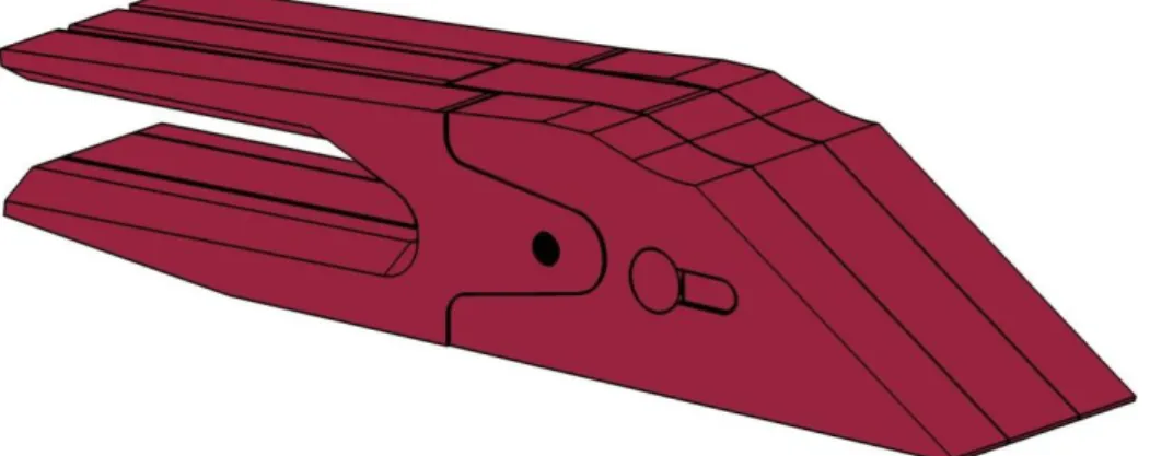
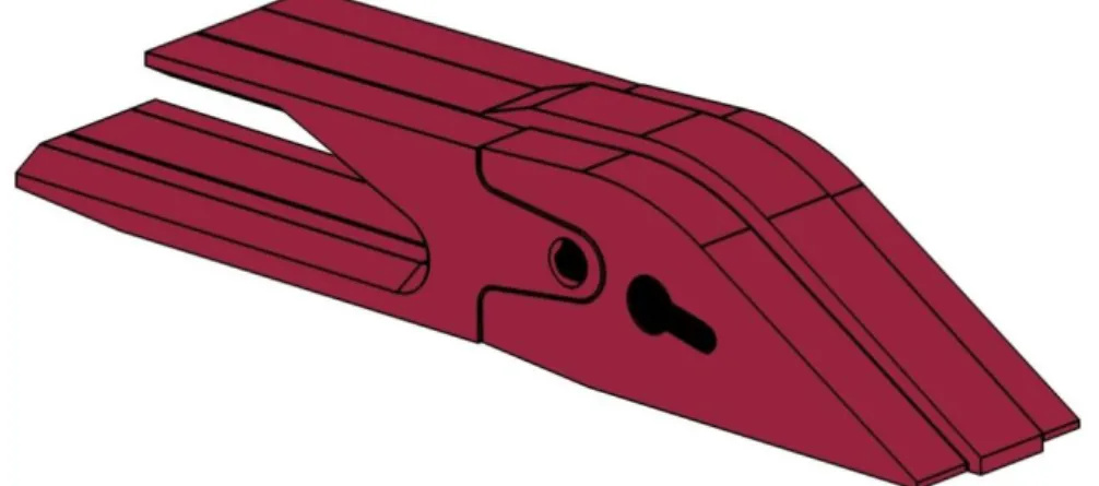
1.1.1 Version one
Today, a concept is being tested locally at SSABs facilities in Oxelösund. This first concept is made to see if it was even possible to make bucket teeth from steel plates and to start testing the wear. Figure 1 shows the whole bucket tooth. Both the adapter and the tooth is made of three pieces of plates, two with the thickness 40 mm and one with 50 mm.
The adapter is made of Hardox 450 plates that are welded together and a 2mm thin plate that is used as tolerance for fitting the tooth. The tooth is made of Hardox 600. Since Hardox 600 is hard to weld (read more about this in chapter 3.3.1 Welding of Hardox on page 13) a different joining method had to be used. The plates of the tooth are joined by a wedge that keeps the plates from sliding apart and the wedge is held in place by a round bar that are pressed in the right position by an hydraulic machine. To assemble the tooth and the adapter, a locking device is required.
The locking device is made of a round bar with a rubber hose on the middle. The round bar is placed with help of a hammer and the rubber hose keeps the bar from slipping out. Initially the bar was made of steel SS235 but this one cracked. To solve the problem, Hardox round bars were used instead which solved the problem. An analysis of the bucket tooth and its parts are find in 4.1.1 Problem analysis on page 17.
Figure 1- Version one of bucket tooth
Adapter Locking device
Problem formulation
In order to expand the market and the use of Hardox steel, SSAB wants to examine the possibilities of making bucket teeth of three or more compounded pieces of steel plates. To ensure the market and the costumers that it is a winning concept, the new bucket tooth has to be cheaper and/or have a longer lifetime than the existing one. This means that the shape has to be adapted for minimal wear over time. The amount of wear (%) during the lifetime is also important, the more the better. The tooth is preferably sharp during the whole use of its lifetime and fulfills the initial demands and expectations of a bucket tooth. This includes easy change without special tools and assurance that the tooth cannot be dropped. This means that a locking system will be developed that fits the requirements.
Aim and research questions
The aim for this project is to examine if it is possible to produce bucket teeth in Hardox steel and if it is profitable to do so. A new locking system will be created. Following research questions are to be answered during the project to ensure a result. The questions are presented in a prioritized order were RQ 1 is most important. RQ 2, and RQ 3 are considered secondary but will be kept in mind during the whole project.
RQ 1: What locking devices are effective for assembling two parts so that the tooth can be changed in the required time? (For list of requirements see Appendix 1)
RQ 2: How does the use of steel plates affect the wear compared to cast steel?
RQ 3: How should the tooth be designed to protect the adapter so that the adapter can have at least double the life time?
Project limitations
The project covers 30 credits of advanced level points during the period 18th January to 10th June. The project is located at SSAB in Oxelösund and at Mälardalen University (MDH) in Eskilstuna.
The project is focused on investigating possible solutions of locking devices for bucket teeth and development of the shape of the tooth in order to minimize the wear over time and maximize the wear over lifetime. In order to verify the concept, calculations and field tests will be performed. Due to the time limitations the students will not be able to perform the DEM simulations all by themselves. They will however be able to test their concepts in an already set-up file to verify the wear resistance. The students will show their ability to use a product development process in order to develop this new product. The following limitations apply for the project:
PRODUCT DEVELOPMENT:
- The project will be performed with a structured product development process containing development tools (e.g. FMEA, PDS and competitor intelligence).
DESIGN:
- The design intends a bucket teeth and a locking device for 5.5 inch teeth and bigger.
- The development will include general cost estimates. 3D MODELING:
- The product will be presented as a 3D-model made with Inventor. VERIFICATION:
- Calculations with WearCalc, DEM.
- DEM analysis will not be performed alone by the students. - Field tests.
2 RESEARCH DESIGN AND METHODOLOGY
This chapter describes step by step the method and approach followed in this project. Since this thesis is a about development a product, the overall approach will be based on a product development process.
Product development process
Most product development processes are described in four or more steps. The authors’ previous knowledge is based on the processes described by Ullman (2010) and Ulrich & Eppinger (2008). Ullman (2010) describes the process in five steps:
- project planning - analysis
- conceptual design - product development - product support
The steps conceptual design and product development includes concept generation and concept and product evaluation. Ulrich & Eppinger (2008) on the other hand writes about six steps:
- planning
- concept development - overall design
- detail design - tests
- refinement and production
Johannesson, et. al (2013) means that with a systematic development and an established product development process, the work and design decisions gets well documented. They describe the product development in 14 phases:
- strategic approach - market analysis - feasibility study - product specifications - generating concept - product concept - evaluation/concept selection - layout construction - detail construction - prototype - prototype testing - production adaption - serial version - market introduction
Different projects have different characteristics, therefore the process is different (Ulrich & Eppinger, 2008; Johannesson, et al., 2013; Ullman, 2010).
Since different projects should have different approach for finding the best solution the authors have picked the following steps for this project, see Figure 2.
Figure 2- Product development process
Part one in the project is about getting information and define the problem. This is part of the groundwork that determines the outcome of the project. To get a clear view of what really is the problem the information is narrowed down to a few questions. The data collection and the literature review is then based on the questions to find information to help solve the problem.
In part two of the project concepts are taking form. It is important to keep a broad approach in the beginning to not exclude ideas to early. By using different product development tools the concepts are evaluated and reviewed. Calculations and prototypes are made in this part to make sure that the concept(s) are ready for field tests. Part three is where the concept(s) are being tested at the field. By reviewing the outcome of the tests the concepts are being further developed if needed.
This project is based on a case study at SSAB. In the start-up secondary data will be collected through literature review, interviews and already performed tests at SSAB. The primary data is collected at site with field tests based on theories and conclusions made by the results of a product development process and secondary data.
Case study
This report includes a single-case study. This type of study often includes data collection through surveys and quantitative analyses to answer questions (Yin, 2013). A good case study takes place in real life and contains sufficient information to treat the problem (UNSW Australia, 2013). A case study is often combined with other methods. The purpose is to focus on one or a few specific parts of a big case to describe reality (Ejvegård, 2003).
This case study was made in the form of a product development process and is initiated to SSAB in Oxelösund. The concepts are based on the authors’ innovative ability and developed by the knowledge conducted through the data collection. In co-operation with customers of SSAB, field tests will be conducted to verify the result of the product development process.
Part One
•Problem definition
•Analysis of product and area of use
•Litterature review and data collection
•Interviews
Part Two
•Competitor intelligence •Generate ,evaluate and
develop concepts •Calculations and verifications Part Three •Field tests •Analysis of tests •Futher development •Conclusion and recommendations
Data collection
Data has been collected by three different means during different times in the project. Firstly, to get an understanding of the problem and the product, a competitor intelligence process was conducted. Secondly, with interviews and a literature review, data and knowledge was gathered to be able to generate and create valid concepts. Thereafter, with calculations and field tests the concepts based on the data collection were evaluated. All of which has been used in a single-case study.
2.3.1 Interviews
Lantz (2013) mean that the result of an interview is determined by three concepts; the preparatory work, the interaction during the interview and how the responses are processed. She writes that in a scientific context the demands on an interview are stated as such:
- The method has to give reliable results (demand on reliability). - The result has to be valid (demand on validity).
- Other should be able to critically examine the conclusions.
A part of the preparatory work is deciding which type of interview to use. On one hand you have the open and unstructured and on the other the structured one (Lantz, 2013).
Different kinds of interview techniques can preferably be used in the same study. For example starting with unstructured interviews to get a deeper understanding of the problem and make a semi-structured interview based on the new understanding (Höst, et al., 2006; Lantz, 2013). The structured type is mostly performed in form of a questionnaire with closed questions; this type of interview will not be used in this study.
Unstructured interview is an effective and very useful method while developing an
understanding of a problem or task (Cohen & Crabtree, 2006 b). This type of interview is controlled by a guide with different areas of problem. Within these areas the questions can vary in order and formulation. To ensure that all areas of problems are processed, predetermined times can be set in advance (Höst, et al., 2006).
Semi-structured interviews has some written questions as guidelines but the order can
change as well as the formulation of the question, based on how the interview turns out (Höst, et al., 2006). In this structure open-ended questions are common and give the interviewee a chance to express thoughts of the area in their own way. This can lead to a new view of the topic (Cohen & Crabtree, 2006 a).
In this study mostly unstructured interviews were used to gather information and knowledge from co-workers with years of practices in the field. This is considered by the authors the fastest way of conducting important information in the limited time for this project. In case of customer visits semi-structured interviews were used.
2.3.2 Literature review
This is a type of secondary data collection and is commonly done by searching all relevant printed material, for example books, articles and reports (Ejvegård, 2003). A literature review is preceded by a literature search. One way of finding literature is searching different databases. When using databases it is important to have picked the right keywords, these words will help you find relevant information. The amount of time spent on literature search has to be reasonable to the time limitations of the project (Bell, 2006).
In this thesis the literature review is focused on the material Hardox, production methods and wear of steel. The literature consists of scientific articles from the databases; DiVA, Web of Science, Google Scholar, SSAB, and books from Mälardalen University Library and Västerås Public Library. To ensure the reliability of the study the primary source has always been located. More about the reliability will be discussed in chapter 2.5. To give the best preconditions and relevant knowledge the authors had a narrow scope when searching literature. The chosen topics were carefully selected to answer to the research questions and help with the process. The keywords that have been used when searching the databases for scientific papers are: wear of steel, abrasive wear, gas cutting, and heat affected zone.
2.3.3 Design of tests
During the project both computer aided calculations and tests will be performed. In both computer simulations and tests factors need to be stated before testing. Factors can be divided in (Johannesson, et al., 2013):
- Controllable - Observable - Unknown
Both the computer simulations and field test will be test controllable factors. The computer aided test will be guided by the supervisor of the project because of the time limitations. Field test will be performed at one or more places in Sweden.
The purpose of the test will be to examine the wear of the bucket tooth and if/how well the locking concepts withstand the loads. The tooth and adapter will be weighted before and after the test to measure the wear and analyses of the shape will show where the wear occurs. If the locking concepts not withstand the loads this will reveal itself with a broken locking.
Qualitative and quantitative data
A quantitative data collection is any data collection technique that generates and uses numerical data, like questionnaires. It is often performed with questionnaires containing short answered questions (Bell, 2006). For a quantitative data to be useful it has to be processed and analyses. Analyzing techniques like charts and graphs helps present and examine relationships within the data. Qualitative data on the other hand is usually referred to non-numerical data and can therefore also be collected through pictures or deeper interviews (Saunders, et al., 2009).
A study can be both qualitative and quantitative or used separately (Bell, 2006). This study will use qualitative data gathered mostly from in-house interviews and test.
Reliability and validity
2.5.1 ReliabilityRegardless of the method used for information gathering it is important to always critically review how reliable the information is. To measure the extent to which a method provides the same result on different occasions you can use reliability (Bell, 2006). If the requirements of reliability are not met you lose the scientific value (Ejvegård, 2003). The reliability of a method can be tested in different ways, mainly by an altered way do the same test or ask the same questions but with different words or at a different time (Ejvegård, 2003; Bell, 2006).
The data collection in this project is based on a competition intelligence processes, a literature review and interviews. The literature review is based on articles and books about this specific topic, and to ensure the reliability various researchers’ opinions were considered. Where possible, the conducted data is verified with calculations and tests. Therefore the reliability of this study is considered high. Although, due to the fact that this is in some way a creative work, it is not possible to completely ensure reliability.
Interviews were an important part for understanding and evaluation during the project. For this, unstructured interviews were conducted during the whole project. In light of a scientific approach this gives a low reliability since the answers will differ, depending on whom and when they are asked. Although, the persons interviewed and the knowledge they are carrying is invaluable for this project and cannot be conducted in another way, therefore this should not affect the reliability of this study.
2.5.2 Validity
Ejvegård (2003) explains that validity is a concept that is meant to secure what is really measured and what was intended to be measured. He also writes that using relevant parameters in the model is a certain way of ensuring high validity. In order to provide credible conclusions the study should be designed in a way that enables a valid result and as Sapsford & Jupp (2006) describes it: “…the data do measure or characterize what the authors claim, and that the interpretations do follow from them.”
For this study it will mean to measure the wear, the strength and sustainability of the locking device.
3 THEORETICAL FRAMEWORK
This chapter contains the theoretical framework for this thesis. This is the base of knowledge supporting the results. It begins with presenting the necessary product development tools, and continues with description of the material used. Thereafter, the theory supporting the study for market value is presented.
Product development tools
A short description of the product development tools used in this study is presented below.
3.1.1 Gantt-schedule
Gantt-schedules are commonly used in project management. It is one of the most popular and useful ways of showing activities displayed against time (Gantt, 2016 ). A Gantt chart is a type of flow diagram and is structured with a horizontal time line created with bars representing start and end of each task (Ulrich & Eppinger, 2008). This allows the user to see where each activity begins, what activities there are, how long time they will take, where activities overlap, how much they overlap and when the project will start and end (Gantt, 2016 ).
3.1.2 Products Design Specifications – PDS
PDS is a document created in the beginning of a product development process, often as early as in the problem definition phase. It contains information that creates the groundwork for how to make the product successful. It states the customers’ needs and values. By writing down and then breaking down the specifications in to sub-systems one get a clearer overall view. (Ulrich & Eppinger, 2008)
3.1.3 Quality Function Development- QFD
QFD is a tool to help see and convert the customer requirements to technical requirements, all to help develop a greater product (Ullman, 2010). A properly performed QFD contains information about the customer requirements, technical requirements, the connection between the two and technical correlations and priorities (Prasanna Kumar, 2016).
3.1.4 Competitor Intelligence/ Benchmarking
Ulrich & Eppinger (2008) states that the first step to get a broader view before generating concepts is to search for information externally. By mapping existing products by different competitors knowledge about the product and market value may be found. This is also a fast and effective way of getting to know the market and the product and many times it helps to get an overall understanding of the problem.
“Competitor intelligence is not just for market analysts; it is for everyone, for every decision maker.” - (Fuld, 1995)
Fuld (1995) also states that there is a difference between data and intelligence. To sum up; data is “scattered bits and pieces of knowledge” and intelligence “the implication that will allow you to make decisions”.
3.1.5 Methods for generating concepts
In the phase where concepts are being generated, product solutions that meet the product specifications is to be found. This phase is made in a process that is supported by a systematic way of working and with valid methods. Ulrich and Eppinger (2008) and Johannesson et al. (2013) means that by generating as many ideas as possible the chance of missing a solution decreases. One of the most known ways of doing this is called brainstorming.
While brainstorming, generally there are four ground rules to consider; no criticism, quantity is sought, step outside the box and combining ideas. Brainstorming usually contains five phases; regular ideas, silence or lower the tempo in the idea development, brainstorming is starting to work, silence or less productivity and then unusual ideas is starting to take form. (Johannesson, et al., 2013)
3.1.6 Pugh’s matrix
In order to move forward the concepts need evaluation. Every concept that has been generated in the previous phase is to be valued towards the requirements and preferences in the product design specification. This opens up to some difficulties (Johannesson, et al., 2013):
- The value of a solution is inflicted by many different features. - Different stakeholders value the features different.
- Some features can be measured quantitative and some qualitative. - Complete information of the concepts are missing when decisions has to
be made.
To support an objective evaluation tools as Pugh’s matrix can be used. It is a product development method used to objectively evaluate the concepts that best solves the problem. The concepts are being compared to a reference product and how well they fulfill the requirements. The requirements are weighted to give a review of which concept that has the best correlation between customer requirements and the importance degree of fulfilled result (Ulrich & Eppinger, 2008).
Discrete element method (DEM)
Discrete Element Method (DEM) is a computing method for motion and effect of a large number of small particles and it is commonly used in mining industry. Each particle is affected by a force computed from the particle properties, interaction laws and contact models. By using this, one can simulate the interaction and hence the impact and wear of steel digging in rocks. (Luding, 2008)
Hardox steel
Only 40 years ago, producing wear plates was an impossible mission for most steel producers. Some manufacturers at the Swedish steel company SSAB thought differently and attacked the issue. In 1974 Hardox came out and since then it has become thicker, thinner and harder without sacrificing the overall important toughness (SSAB, n.d. b).
Hardox is built to take a beating. Sand, rocks, scrap metal and sand are common hostile materials and they all have a hard time making a lasting impact on Hardox wear plates. It is extremely wear resistant and can extend the service life of your equipment. Figure 3 shows that Hardox has at least three times longer service life than normal steel (SSAB, n.d. c).
Figure 3 - Service life
Hardox is built not to crack. Making a hard steal is not the hard part. However, creating steel that is hard throughout the whole process is a challenge. Its biggest difference compared to normal hard steel is the toughness. Hardox can be bent, formed and welded without losing its properties which makes a lighter design possible. Figure 4 shows the strength, hardness and guaranteed toughness in the different materials which SSAB provides, as well as normal S355 steel (SSAB, 2015 d).
SSAB offers different types of Hardox. Hardox wear plates are shown in both Figure 4 and Figure 5. It comes in a variety of thicknesses from 0.7 mm (Hardox 450) up to 160 mm (Hardox HiTuf) and the main difference is the hardness (SSAB, n.d. e). They are graded with help of the hardness test Brinell, measured in HB.
As well as plates, SSAB offers Hardox round bars. They come in diameters between 40 and 70 mm and lengths up to 5000 mm. They also feature the same guaranteed properties as the wear plate (SSAB, n.d. f). The Hardox round bars are new on the market and are offered in Hardox 400 (Lindström, 2016).
3.3.1 Welding of Hardox
Since Hardox steel is special steel with high hardness and yield strength, there are things to consider when welding (SSAB, n.d. a):
- Choice of welding consumables - Preheat and interpass temperature - Heat input
- Weld sequence and size of root gap in the joint
A heating procedure applied to the steel components immediately before welding is considered as an essential part of the welding operation and is called “preheat”. Preheating can be applied only at the place where you are going to weld, or at the entire component. The main reason of preheating is to counteract that the component(s) cool too quickly after welding. This protects the steel that is being welded from the fast cooling cycle created by the welding process. The preheating may be carried out for any of the following reasons (BOC, 2007):
- Slow down the cooling rate - Avoid cracking
- Reducing Shrinkage, stress and weld distortion - Promote fusion
- Remove moisture
Manufacturing techniques
Hardox plates can be cut with cold methods (i.e. water jet cutting, sawing and grind cutting) and thermal methods (i.e. gas cutting, plasma cutting and laser cutting). The thicker the plate, the greater risk of cracking on the cutting edges, but by preheating the material and use a slower cutting speed the risk of cracking can be reduced. Table 1 shows the general data for the different cutting methods (SSAB, n.d. g). Read more about HAZ (Heat Affected Zone) in chapter 3.4.2 below.
Table 1- General data for different cutting methods (SSAB, n.d. g)
CUTTING METHOD CUTTING SPEED CUT WIDTH HAZ TOLERANCE
Abrasive water jet 8-150 mm/min 1-3 mm 0 mm ± 0,2 mm
Laser cutting 600-2200 mm/min < 1 mm 0,4-3 mm ± 0,2 mm
Plasma cutting 1200-6000 mm/min 2-4 mm 2-5 mm ± 1,0 mm
Oxy- fuel cutting 150-700 mm/min 2-5 mm 4-10 mm ±2,0 mm
3.4.1 Oxy-fuel cutting
The oxy-fuel cutting process starts with that the material first heats up to the kindling or ignition temperature, thereafter a jet of pure oxygen is directed at the heated spot. This causes a chemical reaction called oxidation. When the oxidation happens rapidly, like in this process it is called combustion or burning, otherwise when the same chemical reaction happen much slower it is called corrosion. The chemical reaction caused by the high temperatures creates iron oxide that accelerates the preheating of the object. This makes the melted material run of as slag (United States Navy, 1996). When cutting a plate that is 30 mm or thicker there is a risk of loss of hardness where the distance between two cuts is less than 200 mm (SSAB, n.d. g).
3.4.2 HAZ (Heat Affected Zones)
HAZ is the area of material which is not melted during heat intensive cutting or welding process but has had its microstructure and properties altered from the welding process and the following re-cooling (Weman, 2003). See describing picture in Figure 6 below.
The hardness properties of HAZ depend on different factors:
- Whether or not the steel was tempered during manufacturing, and if so, how it was carried out.
- The chemical composition of the steel.
- The impact of the thermal treatment from the cutting process.
Oxy-fuel cutting has the highest thermal impact which also makes the widest HAZ impact since the width increases with increasing temperatures. Figure 7 describes the HAZ after thermal cutting of Hardox and Strenx with different cutting methods (SSAB, n.d. g).
Plasma cutting on the other hand has a smaller HAZ and is therefore better for cuttings with finer tolerances (SSAB, n.d. g), see Figure 8.
Toolox
Toolox is developed from the concept of Hardox and Weldox and have the same low carbon metallurgy. This makes it easy to machine and all grades of Toolox can be oxy-fuel cut, welded and bent with good result. Toolox have a tensile strength on 1450 MPa and compared to conventional tool steel it has a three to four times higher impact resistance. Toolox round bar is available in 33 and 44, where the different is the tensile strength. (SSAB, 2013 .h)
Figure 8- HAZ impact from thermal cutting (SSAB, n.d. g) Figure 7- Hardness profiles in HAZ after thermal cutting (SSAB, n.d. g)
Wear of steel
There are different types of wear but in the mineral and mining industries the main wear mechanism is impact abrasion and sliding abrasion. Abrasive and wear- resistant steel “AR-steel” has been developed, which possesses high hardness, good toughness and weldability (Öhman, 2010). AR- steel has high hardness, high tensile strength, high yield strength and high toughness/ductility. Hardox is considered an AR- steel. (SSAB, 2006)
A study from Kulu et al. (2015) tells that materials with higher hardness have lower wear rate. The study also shows that for Hardox steel the wear rate decreases with increases of the hardness. To guarantee a high wear resistance the material hardness must be higher than the abrasive hardness, and if the material hardness is lower the fatigue properties are important.
A different study of wear between two different teeth which are cast is shown with the same relationship between material hardness and wear.
Table 2- Test of hardness and wear time
TOOTH HARDNESS [HB] COST/CHANGE RUN TIME COST/HOUR
Tooth A 450 5 000 SEK 100 h 50 SEK/h
Tooth B 550 15 000 SEK 600 h 25 SEK/h
The study is performed in an ore mine and has compared the running time of two different teeth. Tooth A is cast in China and is both cheaper and softer than Tooth B. As seen in Table 2 the run time differs significantly. The harder tooth, tooth B, who is three times more expensive has a six time longer run time. This makes the harder tooth twice as profitable which shows a connection between hardness and wear resistance. (Thelander, 2016)
Comparing cast steel and plates
A study by SSAB (2006) shows that AR-steels are tougher/have higher ductility. It shows that this is because the plates do not suffer from casting defects since they have been rolled. It also states that the quality and the casting process affect the material properties due to pores and casting defects.
WearCalc
Software provided by SSAB to calculate components and optimize the choice of wear plate. It allows the user to calculate the service life for all Hardox wear parts of different grades and compare them with other wear plates. The sliding wear model is based on two limiting curves representing the types of surface damage, plastic or cutting. The relationship between the hardness of the steel and the hardness of the abrasive material determines the damage mechanism and thus the relative service life. (SSAB, n.d. g)
4 CASE STUDY
This chapter presents the product development process preformed in this thesis. This project is an ongoing project at SSAB which means that some preparatory work has been done and depending on the result, the project will continue after the period of time for the thesis.
Startup/data collection
The start-up of the project included problem definition and understanding, conducting a time plan and a method to ensure that the result will be valid and reliable.
To ensure that the company and university are in understanding a project aim document was set-up. The document states the problem definition, the limitations and the primary and secondary goals. When formulated it were approved by both supervisors from the company and university. The full document is available in Appendix 2.
4.1.1 Problem analysis version one bucket tooth
In chapter 1.1.1 Version one, the concept that makes the basis for this project is presented. By analyzing the performance and functions of the concept the authors will find the weak spots and see what needs to be changed.
Locking device: the locking device is made of a simple Hardox round bar that is
hammered in and held to place with a rubber hose. Previous tests (read more about these below) show that a round bar with the same cross sectional area but different steel cracked. The problem causing the cracking is shear forces. The plates from the tooth and the adapter create a scissor-effect that brings a big shear force on the locking pin. See Equation (1) for mathematical description of shear force.
𝜏 = 𝐹 𝐴⁄ (1)
The locking pins’ function is to prevent the adapter and tooth to come off, it is not meant to take up forces that cause the shear. Those forces are meant to be controlled by the connecting faces between the adapter and tooth. The blue faces in Figure 9 shows the connecting faces.
Geometry of the tooth: An interview with the machine operator from the previous test
made it clear that the bump on the upper side of the tooth makes it harder to dig. It will also make the stones bounce and make an even bigger and faster wear. Another function of the tooth is to protect the adapter since it is meant to have as long service life as possible. Also, since the first locking pin cracked due to the shear force, the geometry of the connection faces needs to be corrected.
4.1.2 Analysis of test 1
The pre-concept has been through a period of field test on the site at SSAB Oxelösund. This gave an insight in how the wear would affect the geometry. This study is not entirely relevant, since the test is conducted in slag giving a different heating effect on the material. Figure 10 shows an illustration of the wear.
Besides the wear the tests also gave indication of the sustainability of the locking. As mentioned earlier, the first round bar in SS235 steel broke, but further tests showed that round bars in Hardox did not break. The test where conducted on a wheel loader and therefore had significantly greater wear underneath compared to an excavator.
Customer visit
To get an insight in the market and to meet a possible customer for production and further field test the authors visited Cerapid in Uddevalla. Cerapid designs and construct buckets and other equipment for construction machines.
To help keeping a good dialog a 3D printed model was made, see Appendix 3. The meeting resulted in information of what to think of when designing bucket teeth, i.e. how big impact dirt have and that it gets in everywhere. Also some good point on the geometry of the tooth, based on the 3D model, like the cavity on the top of the tooth will provide more wear and that it is a good idea to have the middle part a bit bigger. See Appendix 4 for full notes from the visit.
Competitor intelligence
As explained in 3.1.4 Competitor Intelligence, this is a time effective and valuable way of getting to know both the product and the competition. Although, since the competitors’ products is quite different from this one with its molded shape the authors still found it important to do a study of them. Despite the big differences in production method the authors found useful information. Besides inspiration on
A= Used
B= Original
A
B
locking devices, information about overall dimensions on both tooth and adapter were collected. See Appendix 5 for competitor intelligence.
Generating concept/brainstorming
A brainstorming session was made to bring forth new ideas and thoughts. When brainstorming was made the authors used the method called Brainwriting (UCO, N.D.). The authors have used different methods in previous projects and therefore decided to change the method to a better and more open-minded. The authors made it clear for each other how they had changed the method and started generating ideas. They started by listing as much ideas as they could individually in 20 minutes. Focus here was not finished ideas, more like words that could later on reveal something. When 20 minutes had gone, a change of method was done. Instead of presenting the thoughts behind every idea/word they had written, the other participant(s) had to interpret what the other one had written in some way that it could solve the problem. This led to several ideas from every word. Under the whole session it was important that no criticism or judgement was made because judgement stops the creativity process in every individual (Balackova, n.d.).
When the first step was done, the authors started going through each of the words/ideas. The goal was to try developing sketches from them, maybe by combining two or three. This resulted in twelve pre-concepts, on the next pages these concepts are presented.
Concept 1
A concept where the middle section of the tooth is threaded. By placing a threaded rubber inside and then have a sprint with increasing thickness it will allow the sprint to be threaded on and expanding the rubber. A problem is how to allow the threaded sprint stay put and not vibrate out under its use.
Concept 2
Some sort of solution, similar to a hair pin. To lock the tooth into place you press in the pin allowing it to stay in place because of its shape and the pin flexing in and out. Thoughts on this are that it might not be as sustainable as a round bar and how to take out the pin without a special tool.
Concept 3
A three part locking solution containing a main part that will work as the part that takes up all forces, a middle part that has the same length as the middle plate on the tooth and a sprint that connects them all. By pushing in the locking device and turn the sprint 90 degrees the middle part will follow and lock it in place. To take off the tooth you turn back the 90 degrees and push it out. Thoughts on this are that it has similar shape as the round bar, which makes it sustainable. A problem can be that it might be hard to take the locking device out if it gathers dirt inside, which is a common problem in this environment.
Concept 4
Since the old concept with a Hardox round bar is working perfectly fine except for the need of hammering it in the thoughts for this concepts is a special tool. By making a special tool one can ease assembling and dissembling of the sprint. Thoughts on this are that it can be a high cost since you have both a locking device and a special tool.
Concept 5
A three part locking solution containing: a square tube, a rubber part and a metal part. The square tube goes through the tooth and has a square hole with the length of the middle plate. The rubber is designed so it can flex effectively and can fit inside the tube. The metal part has the size of the square hole and can flex out a little before it stops because of the chamfers. When the rubber and metal plate is attached into the square tube it can be pressed into the tooth. This allows the metal plate to be pressed in, thanks to the rubber. When it is pressed in completely the rubber will push the metal plate out again securing it in place. Thoughts on this can be that it might need some kind of hammer to get the tube in and out. A square tube has sharp edges making the possibility of cracks higher on the tooth/adapter.
Concept 6
It’s a three part concept, containing two plates with a loop on them and a spring. The spring is thick and works as the part withholding all the forces. To assemble the locking device, first attach the spring to one of the plates and the put it through the tooth. Take a hook and drag the spring out on the other side so that the other plate can be attached. Now the spring will pull the plates towards each other securing the tooth in place. Thoughts on this can be that the spring needs to be very thick to not crack and if it is thick it will be stronger. This makes is harder for a person to drag out the spring when attaching it. The side plates will be on the outside of the tooth making them vulnerable towards wear.
Concept 7
Same idea as the existing solution when assemble a tooth without welding. The wedge that you place inside will be threaded as well as the sprint. Instead of press fitting it with a force of several tons you screw it into place. The sprint can be made in Hardox and therefore will be sustainable. Although some sort of locking solutions for the screw might be needed so it stays in place and becomes reliable.
Concept 8
The ordinary ink pen you can see on most offices. By using same concept where you have a sprint that you place inside the tooth. When the locking device hits the end, the pin travels in and forces the middle section (has the same length as the middle plate on the tooth) to expand and locks it in place. To take it out you use a hook of some sort to drag it out forcing the middle part to go back into the sprint. Problems with this can be all the parts that will be needed. What happens if dirt gets into the locking device making the mechanism unreliable?
Concept 9
Development of the existing locking device where the rubber is too thick and you need to use a hammer to get it in and out. By having two smaller rubber rings that you place into the middle plate and then press the sprint through the rings. The sprint has two tracks where the rubbers will expand back to its normal shape securing the sprint. Thoughts about this concept might be that it still needs to be hammered in. The old concept is working and now when the rubber pressure is reduced, it might not be enough.
Concept 10
Some sort of tube that somehow can expand. Maybe through a tube that is thicker in the middle section. When you press a smaller sprint through the tube the thicker part gets forced out which locks the sprint in place. Thoughts could be that you will need a hammer for an assembly as well as a disassembly.
Concept 11
A three part solution containing: A Hardox round bar, a magnet and a mount that holds the magnet. To assemble it, place the magnets in the mount and then place it inside the tooth. Take the round bar and put it in from the other side off the tooth until the magnet attracts with the bar locking it in place. Problems with this can be if dirt gets between the bar and the magnets preventing it from getting maximum attraction. Is it enough power in the magnet when revealed to extreme conditions? How do you dissemble it?
Concept 12
A further development for all systems that becomes unreliable because of dirt. When it is locked and it is hard to get out because of dirt you turn it the other way forcing it to go off, which means that you can remove it later without losing important time.
Concept evaluation and development
With knowledge from the literature review, interviews and the competitor analysis the concepts were developed and screened out one by one. This process rarely happens in a straight line. Concepts are developed, evaluated and then developed again. The following is a description of the processes in the best way possible to keep a red thread.
4.5.1 First selection
When the twelve concepts were made an evaluation had to be done in order narrow it done and find strengths and weakness in every concept. As mentioned earlier in the report, the authors was located at SSAB and where surrounded by highly educated people with great experience. The authors took advantage from this and started consulting with them about the concepts. Focus was in what concepts that were preferred and why, as well as what could be a problem in every concept. It did not take much discussion before seeing a pattern in the different concepts. For example, concept 11 was preferred, but there was some concern about how strong the magnet bound would be.
When the authors had enough information about the different concepts it was compiled and then discussed with the supervisors. The discussion help narrowing it down to five concepts. The concepts where only build by ideas and quick drawings, which made it hard to really see how they worked. With help of CAD all five concepts where created.
Concept 11 – Magnet mount
Change: Both the magnets and the holder for the magnet (the part to the left) has a hole. This allows the user with a thin sprint to push the right part out.
Concept 11 – Bayonet twist lock
Change: Since the magnets might not be as reliable as needed. The authors made a similar concept with a bayonet groove. This allows the sprint to follow the groove until it is locked. A magnet is placed inside the left part which attracts the holder.
Concept 3 – Twistlock
No further changes towards the previews concept.
Concept 5 – Square bar
No further change towards the previews concept.
Concept 6 – Spring
No further changes towards the previews concept.
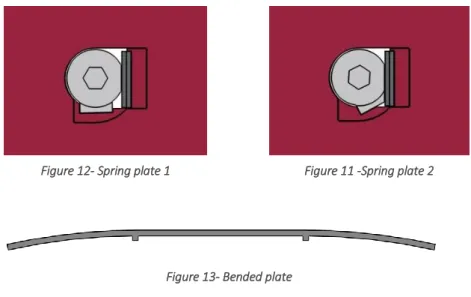
Spring plate
At this state in the project a new idea took form. This is a two part concept with a sprint and a plate. The basic idea is to use a thin plate as a spring. The plate has a thickness of 2 mm and two small ribs with 52 mm distance on the middle of the plate. These two ribs help the plate from sliding out since the stays on each side of the middle part of the adapter. The other part is a sprint with two bumps near the edges. First insert the plate and then the pin, see Figure 12 and Figure 11. By rotation the pin the bumps presses the plate making it bend, see Figure 13. This would make the plate stay in place and prevent the tooth from detached from the adapter.
Figure 11 -Spring plate 2 Figure 12- Spring plate 1
4.5.2 Second selection
The concepts were, after the first pick further developed. After the development the concepts were evaluated with support of a QFD. The customer requirements were identified earlier by interviews with experienced co-worker, on customer visits and from studying competitors. Description of the requirements and approach is found in Appendix 6.
This evaluation tool showed that the weakest concepts is “ Spring”, mostly because for the spring to maintain for the loads it would have to be so large that it would be almost impossible to pull out. It would also require some type of special tool. The strongest one on the other hand is the “Bayonet twist lock” which is more secure than the “Magnet Mount” since it will be less affected by dirt and more reliable.
“Square bar” is considered less sustainable since the area where the rubber is mounted also will area that will take up the most forces and will make it easier to crack. The concept “Twist lock” has a high risk of not be able to disassemble because of dirt.
The QFD were not filled out completely since the concepts are not developed enough to have all the information and this is the information the authors find relevant this time in the process.
The concept “Spring” will not be further developed from this point since the authors find the risk of injury when using is too high. For it to work safely, not only a lot of changes has to be done, it probably will need advance external tools as aid. If it is compared with the spring, the magnet mount has a solid round bar throughout the entire lock meanwhile the “spring” concept has a spring as the locking device. This will make it a lot less sustainable.
4.5.3 Development of Magnet Mount and Bayonet Twist Lock
Magnet mount and Bayonet twist lock got the highest score from the QFD. They are both based on the same concept and seem promising. The authors liked the magnets and how easy an assembly was. In the Bayonet twist lock they saw potential in the groove. By using the best from both concepts a new one was designed. It is the same idea but the groove has been changed. This allows it to go back up a little after the twists, securing it in place, see Figure 14.
In previous concepts, the magnets where mounted in one of the part attracting to the other part. In this concept the magnet is mounted on both parts and instead them being attracted to each other they repel, forcing the sprint to stay in place inside the groove.
To see how the concept really worked, a prototype was made, see Figure 15. The prototype worked better than the authors expected and gave a good idea of how the locking behaved. The result was a good locking ability and a confidence-inspiring sound when it snapped into place. A problem that could be assumed was that the magnets could be too weak to ensure a good locking ability.
The authors therefore tried taking the same head but instead of a magnet in it, they used an elastic rubber. The result was much better. It gave the same trustworthy sound when it snapped back. It required a greater force to push the sprint out of the groove, making it much more reliable.
The authors found out that there is a gap between the lock and the middle part of the tooth. To clarify the problem, see Figure 16, where the pin is at the back and ready to be turned. It has a gap on around 1 mm. Figure 17 shows how the sprint is when it slid into the groove and locked itself. It has a gap on around 5 mm, which means it can slide around 5 mm when it is in locked position. The gap also allows room for dirt to penetrate and make it more difficult once the removal will take place.
Figure 15- Prototype of Bayonet Figure 14- Concept Bayonet
By shortening the length of the thick part on the sprint, it made room for a rubber part threading on the pin. When you then lock it, the rubber part compresses the 5 mm which was previously a backlash. As the part then is in the locked position, the rubber part will be in its normal state and avoid the sprint to slide around, see Figure 18.
When the concepts was presented to the supervisors, they where positiv and thought this was a promising conept. Next step was to see how the bayonett could be manufactured. After having contact with people at SSAB as well as Bengt at MDH, it seem like it would be kind of difficult to manufacture the groove. The authors therefore started looking on other parts with similar designs and how they where manufactured. The conclusion was that it would be a lot easier to manufacture, if the groove went all the way through. This didn’t affect the function, it rather improved it. Now it was easier to manufacture and not as affected by dirt. The groove was made at both sides and the sprint had a roundbar sticking out on both sides. This allowed the bayonett to have equal force on both sides instaed of all force on one side.
Figure 18- Illustration of rubber part
Figure 17- Illustration of gap with pin locked Figure 16- Illustration of the gap
The end of the sprint that fitted the groove, which in previous concepts had to be milled out now was a roundbar. This gives the manufacturer the option to just press in a roundbar or maybe weld it in place. See Figure 19 for illustration of the groove and pin.
4.5.4 Development of Twistlock
After visiting Cerapid we received valuable information about the Twistlock. The big problem according to them was that there could be problems with dirt when to unmount the lock. The authors therefore changed the shape of the center part so that it could move more freely even though the dirt was there (see Figure 20).
Two important points that should be met to be able to get a good end result is; Ease the manufacture and figure out how to allow the Twistlock to stay in locked position. The authors saw good potential in previous presented concept, Spring plate. Allthough it had a lot of complicated parts that had to be changed. After talking with the supervisors a decision was made to test the concept and if it would worked it could be aggregated with the Twistlock. A prototype was made (see Figure 21). As expected it had some problems because of the complicated manufacture. The possitive thing was that the Hardox plate was very flexible and could be used in the twistlock.
Figure 19- Development of the groove
Figure 23 - Cross sectional view of Twistlock
By changing the shape of the main part it now has a finnished profil from Tibnor (2012). Instead of processing the middle part it now contains of two plates and one tube that are welded togehter. This part is then welded on to the sprint, which secures it in place allowing it to only rotate. The plates are now shaped so that they are pointing out. When you lock the TwistLock, the plates bends out to its normal state. This secures the Twistlock assemled in the tooth. For a disassembly, it requires more torque because the plates must be bent into the middle section. Figure 22 shows a developed model of the concept.
Figure 23 shows an cross sectional view out off the tooth mounted with twistlock. The authors didn’t want the thin area of the twistlock to receive the external forces, therefore they designed the square bar so that the thicker area is longer on both sides allowing it to receive all forces. This results in the area increasing from 118 mm2 to 351 mm2, allowing it to be three times stronger Euqation (1) on page 17.
4.5.5 Development of Square Bar
By looking at the QFD it shows a big problem with how ineffective the material usage was. The design of the square bar made the manufacture more complicated than it had to be. If you instead use a solid rod it will increase the sustainability (see previous chapter 4.1.1 for shear). In the previous version of the concept the rubber was assembled with a steel plate and then pressed into the square tube. By using a dovetail router bit, all you need is a processing from the side and the part is complete, see Figure 25. Then just press the rubber side, no additional fastening is required because it is under pressure when mounted.
A prototype was made to see how the rubber would behave. This led to a problem being found. When fitting the square bar into the tooth it works fine until it hits the rubber. Because the rubber is very soft it just slides sideways until it stops instead of being pushed down.
By placing a thin metal plate as a shell for the rubber it allows it to be pushed symmetrical. The authors tried this and it behaved as they wanted. See Figure 24 to see the metal plate as well as the prototype.
One problem that still remains was that the pipe had sharp edges. This could lead to severe production when the tooth is produced by gas cutting. The authors began to investigate the square profiles that already exist, to avoid further processing. This led to the discovery of existing profiles through Tibnor which is owned by SSAB (Tibnor, 2012). See Figure 26 for illustration of the concept.
Figure 25- Square bar 1
Figure 24- Prototype Square bar