V¨
aster˚
as, Sweden
Thesis for the Degree of Master of Science in Engineering - Robotics
30.0 credits
INTELLIGENT ROBOTIC GRIPPER
WITH AN ADAPTIVE GRASP
TECHNIQUE
Johan Johansson
Jjn12025@student.mdh.se
Pontus Pettersson-Gull
Ppl12001@student.mdh.se
Examiner: Martin Ekstr¨
om
M¨
alardalen University, V¨
aster˚
as, Sweden
Supervisor: Fredrik Ekstrand
M¨
alardalen University, V¨
aster˚
as, Sweden
June 28, 2018
Abstract
This thesis presents a robotic gripper with an intelligent sensor system to grasp objects with an adaptive grasp technique. Two techniques are used, one for small objects and one for large objects. The sensor system is able to detect the object and measure its size to adapt the grasp. Optical motion sensors are used to see when the object is slipping between the fingers which means that more force needs to be applied. This makes it possible to grasp rigid and soft objects without damaging them. The functionality of the gripper was tested on eight objects with various characteristics. The results show that it can adapt the grasp technique and grasping force to the objects’ size and softness. It also shows that adding one more grasp technique made it possible to grasp more objects, compared to a different gripper with a single grasp technique which were used as a foundation for this thesis.
Table of Contents
1 Introduction 3 2 Background 4 2.1 Pre-touch . . . 4 2.2 Slip Detection . . . 5 2.3 Tactile . . . 5 2.4 Design . . . 5 3 Problem Formulation 7 4 Method 8 4.1 Evaluation . . . 8 5 Design 9 5.1 Overview . . . 9 5.2 Hardware . . . 11 5.2.1 Arduino Shield . . . 11 5.2.2 Actuators . . . 11 5.2.3 Sensors . . . 13 5.3 Software . . . 13 5.3.1 Pre-Shape . . . 14 5.3.2 Choose Grasp . . . 15 5.3.3 Anti-slip method . . . 15 5.3.4 Grasping System . . . 155.3.5 State I - Grasp with fingertips . . . 16
5.3.6 State II - Grasp with both fingers . . . 16
6 Experimental Test Setup 18 6.1 Test I - Grasp different objects . . . 18
6.2 Test II - Quantitative test . . . 19
7 Experimental Results 20 7.1 Result Test Setup I . . . 20
7.2 Result Test Setup II . . . 20
8 Discussion and Future Work 27
9 Conclusion 29
References 30
1
Introduction
The human hand is an advanced construction, both sensory and mechanically. It is able to grasp objects with high precision and strength using its 29 joints and 34 muscles. Constructing a robotic hand similar to the human hand would require immense amount of work to mimic all movements and sensory data. Externally the sight helps us to locate the object and to estimate the weight and material of the object to prepare for a grasp. Through trial and error we have learned how to grasp objects with many different characteristics and to adapt the grasp technique accordingly.
As robots get more and more diverse they become more important in our daily lives. A household robot for example, which needs to be able to handle many different objects in a non structured environment, unlike the early industrial robots which were designed to handle specific objects during controlled circumstances. An optimal design would be a gripper which works independently without any external sensor or vision system. All computations would be done internally and all information about the object to be grasped should be collected from the sensor system integrated in the gripper. To achieve this different kinds of sensors are needed, the gripper needs to see the object to adapt the grasp and it needs to control its grasp force to grasp without breaking the object. Choosing appropriate sensors and placing them wisely would make it possible for a gripper to grasp unknown objects without any external system.
The thesis is structured in the following way: Section 2 discuss the background and related work, which sensors can be useful and how other grippers are designed. Section3states the research questions. Section4explains the working method and the evaluation process. Section5 describes the hardware design and the overall software system. Section 6 explains the test setup. Section
7 presents the results. Section 8 discuss the weaknesses and how the gripper can be improved. Section9presents the conclusion.
2
Background
Most current robotic grippers are designed to grip specific objects, they are common in factories and can do their task very well. However, these are not flexible and trying to grasp an unknown object will probably cause trouble. These grippers need previous knowledge about the objects to be able to grasp them. Creating a smart robotic gripper, i.e. a gripper which perceives the surroundings and acts independently, will increase the tasks a robot can do. A smart gripper should be working without external sensors, i.e all sensors should be integrated in the gripper and it should be working without an external vision system. The purpose is to aid the main robot when the gripper is mounted. The robot locates the object and moves the gripper towards it, the grasping sequence is fully managed by the gripper. There are some grippers presented by Jin-Siang et al. and Bin-Gao et al. that can handle different shapes and sizes of objects [1, 2]. They have a simple design using only two fingers to grasp the objects. The gripper by Jin-Siang et al. uses only two plates as fingers, thus the gripper can not change the gripping technique according to the objects characteristics. The gripper by Bin-Gao et al. has two fingers with three joints which enables the gripper to grasp different objects in different ways but can not detect an object approaching. The gripper presented by Holm and Anderberg uses two fingers with two joints to grasp objects [3]. Their gripper can successfully perceive an object approaching, shape the fingers around it and determine when the object is within grasp distance. The gripper uses proximity sensors to detect the object, this makes it possible for the gripper to work independently without any external information. When grasping, the IPA gripper uses optical motion detection sensor to see when the object is slipping which means more torque needs to be applied. However, as of now the IPA gripper has trouble grasping several common objects. This might be because it grasps all objects the same way, it only uses the second joint to keep the grasping points perpendicular to the base plate. Using the IPA gripper as a foundation to make a better gripper seems like a good idea, the system to perceive objects works well but the grasping technique makes it hard to grasp many objects. The main focus is to make the gripper more versatile by changing the grasp technique but still keep the ability to perceive approaching objects and grasp fragile objects as well as robust objects. Another important part is to keep the gripper independent, it should be able to grasp objects without being mounted on, for instance, a robot. It should be able to determine when an object is approaching or should be grasped without external information.
2.1
Pre-touch
Pre-touch sensors are often used to detect and estimate the distance to an object. Proximity sensors are commonly used for this purpose and are short-range sensors able to measure distance to an object, without touching it [4]. There are different sensing techniques for these sensors where optical light is the most common one. This sensor is called Time-of-Flight(ToF) sensor and can estimate the distance between the sensor and an object in scope by measuring the time it takes for an optical signal to be sent and bounce back from the object [5].
Lancaster, Yang and Smith use optical proximity sensors mounted on a robot hand providing accurate distance measurements to an object [6] . The robot uses a head-mounted Kinect as vision but due to miscalibrations between the Kinect and the robot’s hand pre-touch sensors were added. A scan from both the Kinect and the pre-touch sensors is made and then aligned using Iterative Closest Point(ICP). By using deep neural network they are able to find regions on an object which contained many geometric features and for each iteration of scans, they re-estimate the pose of the object.
Smith, Garcia, Wistort and Krishnamoorthy use capacitive-based proximity sensors integrated in three different mechanisms: a robot arm with 1 Degree of Freedom(DoF), a planar robot with 3 rotational joints and a two-fingered gripper [7]. The sensor measures the electric field which makes the sensor well-suited for dielectric objects or objects with high capacitance, such as metals or vegetables. The planar robot experiment is equipped with two electric field sensors. The first sensor is used to align the gripper as close to the object as possible, the other sensor determines when to grasp the object. The sensor works well for the alignment, but the sensor that determines when to grasp needs improvement. The biggest problem is the design, as for now the sensor is mounted below the gripper so a small object may not give any response, this can however be solved
with a different design. Another problem the authors state is that electric field sensors may yield the same sensor value for a small object close to the sensor as for a large object far away from the sensor.
The IPA gripper have three integrated proximity sensors per finger that are used for detecting unknown objects. Each sensor is responsible for a certain area. The first two sensors are mounted on top of the fingertip and are responsible for the area in front of the gripper. These sensors are used as collision sensors and make the gripper open up enough to make the object fit in between the fingers. The final sensor is placed in the middle of the fingertip and is used to decide when the fingers should grasp the object [3]. The method works well but the authors state that it could be done with less sensors and that the used sensor have problem detecting objects with smooth surfaces.
2.2
Slip Detection
The torque used when grasping fragile objects is crucial, too high torque will damage the object and too low torque will cause the object to fall out of the grasp. Thus, as low torque as possible while still being able to hold on to the object is optimal. To achieve this it is needed to detect when the object is slipping. Regardless of which sensor is used most control systems to prevent slipping work in similar ways. While the object is slipping the object is not fully grasped and torque needs to be added. The moment the slipping stops the object is grasped with as low torque as possible. An early method of doing this was using acoustic sensors to capture the vibrations when the object is slipping [8].This however would also risk detecting a false slip since the sensors measure vibrations and not the actual slip. A different method is using an optical motion detection sensor commonly used in modern computer mice. These work by taking images of the surface below and comparing them to see position changes in the x-y plane. The LED based sensor ADNS-3530 has been tested and produced good results for slippage detection [9]. Other grippers also use optical laser motion sensors similar to the ADNS-3530 to detect slippage with good results [3, 10]. Another method to detect slippage is using tactile sensors[1]. Although it can successfully detect object slippage it suffers from the same problem as using an acoustic sensor. It measure the perceived slippage when the force changes on the sensor and not the actual slip.
2.3
Tactile
Sensors that mimic human sensory information are commonly used in robotics, particularly when it comes to vision and hearing. These type of sensors do not make it possible for the robot to interact with humans fully which is why the tactile sensor is so important. The tactile sensor is a sensor which mimics the human touch, it can be made to feel both pressure and temperature which makes it a good choice for detection of slippage [11]. An advantage when using tactile sensors as slippage detection is the size and weight. The sensors can easily be homemade by using pressure conductive rubber which is a light material that gets a decreased resistance when load is applied. M. Shimojo et al. have developed their own sensor using this technique and since the sensor is flexible they can shape it so that it fits on the surface of the robot hand [11,12,13]. However, by using tactile sensors as slippage detection it is hard to distinguish in which direction the object is moving which limit the opportunities for human interaction [14].
2.4
Design
The design is a crucial part of how well the gripper will grasp objects. Some grippers try to mimic the human hand as much as possible [10], while others use a much simpler design with two stiff fingers [1]. When grasping objects in daily life all fingers are rarely needed, most objects can be grasped with just two fingers. Thus making a gripper similar to a human hand is not important if it is solely built for grasping. The IPA gripper [3] uses two fingers with two servo motors each. The first servo regulates the opening distance between the fingertips while the second servo keeps the fingertip perpendicular to the base. This means all objects are grasped in the same way. This makes it hard to keep a stable grasp when the object is not grasped close to the centre of gravity, there is no way to keep the object stable between the two fingers. A different two finger solution
is using more joints, which makes it possible to get more contact with the object and make the grasp more stable like the one by S. Nomura et al.[15]. Having more joints enables the gripper to grip around the object and push it towards the palm to stabilise it. More fingers may also increase the stability but require more actuators and sensors which makes the whole system more complex. Another design is the soft gripper by P. Glick et al [16]. By deforming the actuators to match the object’s shape distributes the load and reduce the force needed for each contact point it is possible to grasp a large variety of objects. The control is done through regulation of pressure inside the actuators which stiffens the grip. Although this is a stable and versatile design, it is hard to get full control of the movement and grasping force. It also lack the ability to detect objects due to the difficulty of implementing sensors in the design.
3
Problem Formulation
After testing the IPA gripper and studying related work it has been concluded that the two point grasp is the biggest flaw of the IPA gripper. The number of grasp points can be increased by either adding more fingers or changing the grasp technique. Adding more fingers will create more possibilities but also more problems. The number of actuators and sensors would increase drastically which would demand more computing power and the grasp technique would need a lot of research to function in an efficient manner. Due to the limited time of the thesis work it has been chosen to keep the two finger design of the IPA-gripper and focus on improving the grasp technique. This led to the following research questions:
• How should the gripper be designed to grasp objects that the IPA-gripper could not? • How can the sensors be used to adapt the grip technique for different objects? • How can the anti-slip method in [3] be used when the grip technique changes?
4
Method
The work was done through an iterative design and implementation process. Small parts of the system were separately designed and tested during the work to achieve the fully designed gripper. The gripper was then tested through a quantitative test method described in 4.1 to review the design.
4.1
Evaluation
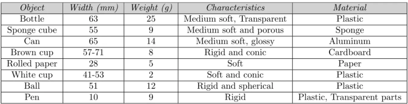
The grip technique was tested on eight different objects: A small plastic cup, a small ball, a rolled paper, a pen and a sponge cube, a soda can, a coffee mug, a plastic bottle. All these objects have different characteristics described in Table1 and evaluate the gripper in different areas. For instance, the pen evaluates the gripper for objects with a small contact surface, the ball test the grippers ability to grasp spherical objects, the rolled paper tests the ability to grasp soft objects without deformation and the bottle evaluates the gripper for heavier and larger objects. Also, the material differ from object to object which gives an understanding of how well the gripper performs in terms of detection and grasping of the objects. The gripper was evaluated by moving the test object towards the gripper and when the gripper indicates that the object is grasped the gripper was lifted. The object is considered grasped when it is positioned between the gripper’s fingers and not moving while the gripper is lifted. To see if an object is still the movement of the object needs to be studied. To measure the movement of an object the slip sensors mounted on the gripper are used, when the sensors output indicates that the object’s speed in the y axis is zero, the object is considered as grasped. The acceleration of the gripper when lifted is measured with an Inertial Measurement Unit (IMU) to easily compare the data of the grasped object and the gripper.
Object Width (mm) Weight (g) Characteristics Material
Bottle 63 25 Medium soft, Transparent Plastic
Sponge cube 55 9 Medium soft and porous Sponge
Can 65 14 Medium soft, glossy Aluminum
Brown cup 57-71 8 Rigid and conic Cardboard
Rolled paper 28 5 Soft Paper
White cup 41-53 2 Soft and conic Plastic
Ball 51 12 Rigid and spherical Plastic
Pen 10 9 Rigid Plastic, Transparent parts
Table 1: Object characteristics, dimensions and weight. The brown and the white cup are slanting, the lower value is the width of the bottom of the cup and the high value is the top. The width of the ball is the widest part of the ball.
5
Design
This section explains the main hardware and software parts of the gripper. First a brief introduction to the gripper, then more detailed sections of each part.
5.1
Overview
The gripper’s appearance is similar to the gripper made by Holm and Anderberg [3] with a few changes. The Fingertip PCB is removed since the new finger sensors are handling the filtering inside the chip, which makes the fingertip PCB redundant. A base plate, seen in Figure 3, is placed at the base of the first joint. The base plate functions as the palm on a human hand to provide support when grasping certain objects, thus it will be referred to as palm throughout the thesis. Two additional sensors are mounted in the centre of the palm. One slip sensor and one proximity sensor. The motion sensor provide the possibility to detect slippage on three points when an object is pressed against the palm. The grasping points are less predictable when grasping around an object, which makes a third motion sensor very useful when not grasping solely with the fingertips. The proximity sensor provides more information before the object is grasped. It is now possible to identify where the object is located between the fingers, which is used to determine when to start the grasp.
One more change is the placement of the proximity sensor on the fingertip facing towards the opposing finger, IR0 on the IPA gripper by Holm and Anderberg [3], FP1 and FP2 in this thesis. The IPA gripper has IR0 placed behind the slip sensor while the proposed gripper has the sensor placed in front of the slip motion sensor. The IPA gripper is using this sensor to determine when to grasp, this is why it is placed behind the motion sensor. When the object has passed the motion sensor it is time to grasp the object. FP1 and FP2 on this gripper has two functions, determine when the object is between the fingers and measure the object width. PP1 on the palm determines when to grasp which makes it possible to move FP1 and FP2 to have more time to measure the width of the object before grasping. This increases the possibility of measuring the widest part of the object before grasping.
It was also chosen that one sensor used on the IPA gripper could be removed. During Holm and Anderberg’s work they concluded that IR2 were redundant for object detection during the pre-shape. The gripper performed similarly with only IR1 pointing inwards at an angle of 20 degrees. In figure2the gripper can be seen along with each sensor’s field of view, the indications can be seen in Table2.
Some changes has also been done with the fingertip design. The new fingertip has an improved way to mount the sensors, the sensors are now slid into the finger instead of being screwed to stay in place which makes it easier to change the sensors if there is a problem. The difference can be seen in Figure1. It also displays the different placement of IR0 (FP1 and FP2).
(a) New finger-tip.
(b) New
finger-tip. (c) New fingertip.
(d) IPA
fin-gertip. (e) IPA fingertip. (f) IPA fingertip.
Figure 1: Comparison between the IPA fingertip and the new fingertip. In Subfigurea,bandcthe presented fingertip can be seen while in Subfigured,eandfthe IPA-gripper’s fingertip is depicted. The placement of the sensors are changed in the new fingertip and are now slid into the finger instead of screwed, as it was for the IPA-gripper.
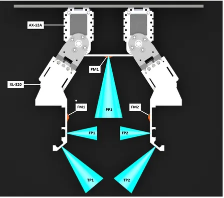
Figure 2: Gripper overview. The blue- and the red cones depicts the field of view of the proximity-and the slip sensors respectively. AX-12A proximity-and XL-320 is the servos used in this thesis. Indications can be seen in Table2.
Designation Type
FM1,FM2,PM1 PMW3360
TP1,TP2,FP1,FP2,PP1 vl6180x
AX-12A AX-12A
XL-320 XL-320
Table 2: Overview of gripper including indication of sensors and actuators.
(a) Palm front. (b) Palm back.
(c) Palm top.
Figure 3: One proximity sensor and one slip sensor was integrated into the palm. The palm provides support when grasping larger objects.
5.2
Hardware
This section explains the different hardware parts of the gripper. 5.2.1 Arduino Shield
The Shield depicted in Figure4 was designed to connect all actuators and sensors in a smooth manner and to fit all needed components on a single board. It consists of the following:
1. Voltage translator (TXS0108E). The proximity modules use 2.8V communication and the Arduino uses 5V. The voltage translator enables communication between them.
2. Tri-state buffer (SN74HC241). Makes it possible to send and receive information from the servos.
3. Voltage divider to power the proximity modules and the voltage translator.
All pull-up resistors used for the I2C communication are also placed on the shield to decrease the size of the proximity module PCB. One resistor for the TX line, one for the RX line and one for each GPIO0 input on the proximity modules.
5.2.2 Actuators
Two different servos are used. The first link of the gripper uses the AX-12A smart servo from Robotics and the second link uses the XL-320 smart servo. Both servos communicate with half duplex asynchronous serial communication and have built in functionality to send current position, load and other useful information. To use this functionality a tri-state buffer were added to be able to send and receive on the same wire. However, due to lack of software for the XL-320 the information can not be received by the Arduino. This is not causing any problems with the positioning as long as the gripper is not affected by any external forces. It is possible to keep
Figure 4: Arduino shield. It was used to connect all actuators and sensors on a single board.
track of the servo movements on the Arduino when the servos are moved only by the Arduino. If the servos would be moved by something else the system would not be able to know their positions. The other data sent from the servo might be useful for further improvements but was not considered due to the lack of time during this thesis. Both servos have internal torque limiters to avoid damaging the servo gears or other mechanical structure. The important servo parameters are stated in Table3.
Figure 5: Actuator system. Each circle represents a servo and the square represents the tri-state buffer placed on the Arduino shield. The buffer makes it possible to receive information from the servos.
AX-12A XL-320 Resolution 0.29◦ 0.29◦ Stall torque 1.5N.m 0.39N.m
Weight 55g 16.7g
Voltage 11.1V 7.4V
Table 3: Servo parameters.
5.2.3 Sensors
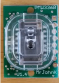
To detect when the grasped object is slipping the PMW3360 1 optical motion detection sensor was used, depicted in figure6. By taking low resolution pictures of a surface it can determine movement in the x-y plane. It is similar to the ADNS-3530 used in [9] but has higher resolution and can detect surfaces further away from the sensor (up to 3mm). It uses the SPI protocol to communicate which makes it easy to use with an Arduino. The sensor is pre-mounted on a board which simplifies the usage with the Arduino 5V output.
Figure 6: PMW3360 is an optical motion sensor that are used as slip sensor.
The pre-touch system uses the vl6180x2proximity module , figure7shows the sensor mounted on the pcb. Compared to the HSDL-9100 used in [3] the vl6180x uses time-of-flight technology instead of measuring the amount of light reflected from the object. Time-of-flight means that the range is estimated by measure the time it takes for the light to return to the sensor. This makes the sensor less sensitive to the colour and surface of the object. Since the vl6180x module has a built in chip which handles the range measurements, the only thing that needs to be done on the Arduino is sending commands and receiving data. This will save computation power compared to the HSDL-9100 which needs a pwm signal to do measurements and the signal is most likely needed to be filtered in some way, in [3] the filtering is done with additional hardware placed on each finger. When using vl6180x the filtering is done inside the sensor module. This made it possible to reduce the amount of components and size of the sensor hardware drastically, a comparison can be seen in Figure8. The sensor uses an I2C interface to communicate which makes it possible to use several sensors with a reduced amount of cables and GPIO pins. It also makes it possible to add more sensors easily.
Figure9 depicts the proximity sensor-system. Since they are I2C compatible all sensors share the same bus. GP IO 0 is the enable signal to power on the sensor, it is also used to change I2C address of the sensor if needed. All signals are wired through a voltage translator to satisfy the operating voltage of 2.8V.
5.3
Software
This section introduces the software system. The code is written in C and implemented on an Arduino MEGA 2560 using the Arduino Integrated Development Environment (IDE).
1http://www.pixart.com/product data.asp?product id=159&productclassify id=1&productclassify2 id=3&partnumber=PMW3360DM-T2QU
Figure 7: vl6180x is a time-of-flight proximity sensor that are used to detect objects.
(a) IPA gripper finger PCB.
(b) IPA finger with sensors mounted.
(c) New proximity sensor PCB.
(d) New finger with sen-sors mounted.
Figure 8: Comparison between the old sensor breakout board and the new sensor PCB. The new proximity sensor handles the filtering inside the chip and therefore the PCB can be reduced. In Subfigurebthe old PCB can be seen and the small circuit board in Subfiguredis the new PCB.
5.3.1 Pre-Shape
The first state of the system is the Pre-Touch phase. It is used to open the gripper and prepare for a grasp when an object is approaching. When the object is detected inside the TP1 or TP2 zone within 60mm the gripper will start reacting. As long as the object is within 60mm in either of these zones the servos will move to open the grasp width. During this phase the fingertips are kept vertical to the palm by moving the second servo of each finger in the opposite direction to the first servo. The gripper stays in this phase until the object is detected between the fingers by FP1 or FP2. When either FP1 or FP2 outputs a distance shorter than the opening distance the pre-shape state is finished and the gripper enters the state were the grasp is chosen.
Figure 9: Proximity sensor-system. The green squares represents the proximity sensors and the orange rectangle is the voltage translator placed on the Arduino-shield.
5.3.2 Choose Grasp
During this state the grasp is chosen by measuring the width of the object. The width is obtained by removing the distance measured by FP1 and FP2 from the opening distance.
W idth = opening − F P 1 − F P 2
However, since the object needs to be grasped when it’s aligned with FM1 or FM2 to be able to sense slippage, the grasp needs to be chosen before the object has passed these sensors. To determine where the object is located PP1 is used. When PP1 outputs a distance shorter than the distance to FM1 and FM2 the object width measurement stops and the grasp can begin, the distance from the palm to FM1 and FM2 is calculated in Equation1.
Start grasp = cos(angle(AX1)) ∗ 52.1 + 10 (1)
5.3.3 Anti-slip method
To detect slippage and apply appropriate force from the actuators a system similar to the Object Motion Focused Grasping (OMFG) by Holm and Anderberg [3] will be used. The main principle of OMFG is: If the object is moving the grasping force needs to be increased. Using this method makes it possible to grasp fragile objects without damaging them while also grasping more robust objects. Sometimes when grasping soft objects the motion sensors can interpret the deformation of the object as slipping, this leads to an increased grasping force even though the object is grasped. To fix this the threshold for the slip interpretation is set to 50 Counts Per Inches (CPI).
5.3.4 Grasping System
The gripper is designed to choose an optimal grasp technique depending on which object that is supposed to be grasped. Two different states are available and which one that is chosen depends
on the width of the object. The first state grasps the object with parallel fingertips while the other state uses a palm to press the object against. The entire grasp sequence can be seen in Figure10
and is described in detail below:
1. The gripper is in pre-touch phase and is still until TP1 or TP2 is affected by an object. The gripper will perform the pre-touch until FP1 or FP2 is affected.
2. The objects’ width is measured and if the maximum width is narrower than 45mm the gripper chooses state I. Otherwise it chooses state II. The width is measured until the objects’ distance to the palm is less than Equation1.
3. The fingers are moved towards the object fast until it touches the object.
4. If no slip is detected the object is grasped and the gripper will hold on to it. If slip is detected the fingers are fine-tuned until no slip is measured.
Figure 10: State machine for choice of optimal grasp technique. Upper branch is state I and the lower branch is state II.
5.3.5 State I - Grasp with fingertips
The first technique grasps objects with parallel fingertips and is used when the objects’ width is less than 45mm, this technique is similar to the one that Holm and Anderberg [3] used. First, the pre-touch phase is performed and the gripper decides to use state I. Second, the servos are moved 5 steps/iteration towards the object until the fingertips touch the object. Third, by measuring slip the gripper is able to fine-tune the fingertips by decreasing the opening width with 2 steps. This means that the gripper will decrease the opening width faster as long as the gripper cannot feel the object and then if slip is detected fine-tune the fingertips. In Equation2and3 the decreased opening width/iteration can be seen in mm. The final grasp can be seen in Figure11a.
No touch = 2 ∗ sin(5 ∗ 0.29) ∗ 52.1 = 2.63674mm (2)
Fine-tuning = 2 ∗ sin(2 ∗ 0.29) ∗ 52.1 = 1.05479mm (3) This technique is applied to small objects since problems may occur if a too small object would be pressed against the palm. The problem is depicted in Figure11cand shows that the fingertips would bump into each other which would create a gap between the object and the surface of the finger. This would result in a failed grasp since the object would be dropped.
5.3.6 State II - Grasp with both fingers
The other technique is used for objects that are wider than 45mm. First, the gripper decides that state II is the optimal state by performing the pre-touch phase and measuring the object width. Second, when the object is placed 10mm in front of the palm the XL-320 servos move towards the object with 15 steps/iteration until TP1 or TP2 are 15mm in front of the object. Third, if slip is detected the XL-320 servos are fine-tuned by moving them 4 steps towards the object. The fingertips are fine-tuned until all the slip sensors confirm that the object is not slipping.
By using the palm a more stable grasp can be made which makes it possible to grasp larger and heavier objects than with parallel fingers. The final grasp is depicted in Figure11b.
(a) State I (b) State II
(c) Problem with state II
Figure 11: a) Final grasp for state I. b) Final grasp for state II. c) Problem that may occur with small objects while using state II. The fingertips may bump into each other, this would create a gap between the object and the surface of the finger which would lead to a dropped object.
6
Experimental Test Setup
To ensure that the results are reliable a stable test environment is crucial. The gripper is mounted on a vertical metal stand which can be seen in Figure 12. The metal stand is placed on a flat surface which ensures that every test object is treated in a similar way. The object is placed on a box and is moved towards the gripper which guarantees that the object is moved at the same height every time. Also, the object is moved towards the centre of the palm which makes it possible to measure the distance to the object by using PP1 on both large and tiny objects. To test the gripper two different tests were performed: Grasping object with different characteristics and a quantitative test. The first test demonstrates which objects that can be grasped successfully at least once while the second test presents a number of how reliable the gripper is. All the used objects can be seen in Figure13and the index’s can be found in Table 4.
Figure 12: Test environment containing: a) Test object. b) Box to place test object on.. c) Gripper mounted on a metal stand.
6.1
Test I - Grasp different objects
The goal with test I was to validate that the gripper can adapt its technique depending on the size of the object and with the chosen technique make a successful grasp of the objects mentioned in section4. The gripper performed the grasp and was then lifted. To see that the gripper was lifted
Figure 13: All objects that were tested. Index’s can be found in Table4.
Test number Object Index
1,2 Bottle 1 1,2 Sponge cube 2 1,2 Can 3 1,2 Rolled paper 4 1,2 Brown cup 5 1,2 White cup 6 1,2 Ball 7 1,2 Pen 8
Table 4: Used objects and which test it was used in.
an IMU (Inertial Measurement Unit)3 measuring acceleration in the y-direction was mounted on the metal stand. By lifting the gripper a force is applied to the test object and a conclusion based on the slip sensors can be made. When the gripper has been lifted and the slip sensors do not indicate any slip, the object could be considered as grasped.
6.2
Test II - Quantitative test
Test II was performed to make a conclusion of how reliable the gripper performs on different objects. To analyse the reliability of the gripper each object was moved towards the gripper 25 times and by counting the number of successful grasps the reliability could be estimated. By performing this test a conclusion of what objects the gripper easily can grasp, but also what types of objects that are causing problems for the gripper, can be made.
7
Experimental Results
To evaluate the gripper two categories for the gripper was used: Successfully grasped and unsuc-cessfully grasped. For the gripper to get a successful grasp the test object needs to be moved towards it, the gripper should perform the pre-touch phase and then choose an optimal technique to grasp the object. After choosing the technique, the gripper should grasp the object and be able to hold on to it without any human aid while the gripper is lifted. Otherwise, the gripper has performed an unsuccessful grasp. In Figure14examples of a successful grasp can be seen.
7.1
Result Test Setup I
In the graphs in Figure 15, 16, 17 and 18 a full grasp sequence for some of the test objects are presented in numbers. Subfigurea shows the measurements for each proximity sensor. Subfigure
b presents how the servo motors are acting during a grasp. Subfigure c shows the output from the slip sensors. Subfigureddepicts what state the gripper chooses, when the pre-touch phase is finished and if the object is considered to be touched. Subfigureepresents the acceleration of the gripper when it is lifted.
As can be seen by analysing the graphs the gripper chooses State I for the sponge, the white cup and the rolled paper while for a wider object, the can, the gripper chooses state II. In Figure
15 it can clearly be seen that state I is chosen, then the gripper is lifted and in that time slip is detected. At that time the servo motors are moved towards the object which indicate that the anti-slip method work as expected. It can also be stated that the gripper is able to adapt its technique depending on the objects’ width, by comparing the rolled paper and the can. The rolled paper was grasped using state I since the width of that object is less than 45mm, stated in Figure15d. However, the can is wider and are therefore grasped using state II which is presented in Figure17d. When slip is detected in Figure17 the servomotors are moved towards the object which indicate that the anti-slip method also works for state II.
7.2
Result Test Setup II
By analysing the data in Table5 it shows what type of objects the gripper easily can grasp and what kind of objects that are causing problems. The white cup and the rolled paper was grasped using state I, these objects were grasped 18/25 and 22/25 cases respectively. A problem with both these objects was that when they were deformed the gripper sometimes perceived it as slip although the object actually was grasped. State I was also used when grasping the sponge, the sponge was grasped 23/25 cases and was the most successful test object while using state I.
State II was used on the can, the bottle and the brown cup. All these objects have similar characteristics: cylindrical or conical and an acceptance for some deformation. All objects were grasped above 80% of the time and when the gripper failed to grasp these objects it was because of the width measurement which led to an attempt with state I instead. When using state I for these objects the XL-320 servos are too weak and the object will be dropped. The brown cup was shifted between upright and upside down during the test, which means that it was successfully grasped regardless of the position of the cup. The gripper had most problem to grasp small and rigid objects such as the pen and the ball. The gripper has a problem to detect the pen and when it has detected it, the pen needs to be placed exactly on the slip sensors otherwise it is impossible for the gripper to grasp it. The pen was therefore placed in front of the slip sensors when the tests were performed. The pen and the ball are two special cases because of their characteristics. The pen was grasped 14/25 times and the ball only 11/25 attempts.
Object Successful grasps/attempt Reliability [%] White cup 18/25 72 Can 24/25 96 Bottle 20/25 80 Sponge cube 23/25 92 Pen 14/25 56 Brown cup 21/25 84 Rolled paper 22/25 88 Ball 11/25 44
Figure 14: Successful grasps for all test objects. State I used on: Sponge, Rolled paper, White cup, Pen and Ball. State II used on: Bottle, Can and Brown cup.
(a) Measured distance from each proximity sen-sor to the object. 255 is the maximum value of the sensors and indicates that nothing is de-tected.
(b) Position of each servo motor. Position 512 is the position when the servo is pointing perpen-dicular to the palm. Considering the mounting position of the AX servos the positional value will always be the same for both servos. If the value increases for XL1 the servo are moved out-wards, while for XL2 the servo are moved in-wards.
(c) Output from slip sensors. The value is either 0 or 1 where 1 indicates slip.
(d) Pre-touch indicates when the pre-touch phase is finished. Grasp present which technique (state I or state II) that will be used and touch indicates when the fingers touches the object.
(e) Measured acceleration in the y-direction, presents when the gripper is lifted.
Figure 16: Test results for the sponge.
(a) Measured distance from each proximity sen-sor to the object. 255 is the maximum value of the sensors and indicates that nothing is de-tected.
(b) Position of each servo motor. Position 512 is the position when the servo is pointing perpen-dicular to the palm. Considering the mounting position of the AX servos the positional value will always be the same for both servos. If the value increases for XL1 the servo are moved out-wards, while for XL2 the servo are moved in-wards.
(c) Output from slip sensors. The value is either 0 or 1 where 1 indicates slip.
(d) Pre-touch indicates when the pre-touch phase is finished. Grasp present which technique (state I or state II) that will be used and touch indicates when the fingers touches the object.
(e) Measured acceleration in the y-direction, presents when the gripper is lifted.
Figure 18: Test results for the white cup.
8
Discussion and Future Work
The gripper has been tested on various objects and the results prove that the gripper is able to detect and grasp objects with different characteristics. The gripper is proven to be independent and adaptive depending on which object that is supposed to be grasped.
The pre-touch works well with only two active sensors, one on each fingertip. The width measurement is working but there are two problems that needs to be considered. First, the proximity sensors FP1 and FP2 sometimes have problem to detect the object because of the material. Second, if the object is moved into the hand too fast, the gripper is not able to update the width measurement fast enough. Both these problems lead to an incorrect measurement of the objects’ width. Due to this, the gripper occasionally chooses state I instead of state II for larger objects. The only time the gripper failed to grasp the bottle, the can or the brown cup in test setup II was when state I was preferred, this only happened when the width measurement failed. Overall, the width measurement is acceptable for its purpose in this thesis but can be solved by optimising the code, then the Arduino can run on a higher frequency which makes the width measurement faster. The anti-slip method works well and the gripper has been proven able to hold on to the object without damaging it while being lifted and shaken. The only flaw with the anti-slip method is that sometimes when an object is deformed the gripper perceives it as slip although the object actually is grasped. This mostly happens on conical objects and depends on the contact face against the slip sensor.
By analysing the results in Section7 it can be concluded that the gripper easily can grasp big objects. However, the gripper has problem to grasp small, rigid objects or objects with special forms, for instance spheres. Two objects of this type was tested during the thesis: the pen and the ball. The pen is narrow and therefore hard for PP1 to detect. The gripper had problem to grasp it because of the contact face which is circular and when slip was detected the fingertips were pressed together which made the pen roll out at the end of the finger until it was dropped. To avoid this and make the gripper perform better sensors that easily can detect these kind of objects are needed. Objects like the pen has to be placed directly in front of the slip sensor to see if it is slipping. A bigger area of slip detection is therefore needed, this can be solved using tactile sensors on the surface of the fingers. Adding one more slip sensor on each finger might also solve this problem, but these sensors are rather big. To fit more sensors the finger would need to be bigger which results in a more cumbersome gripper. A larger finger might create more problems when grasping in state II similar to the one depicted earlier in figure11c. The ball was difficult for the gripper to grasp since it needs to be grasped on the circumference, otherwise the ball would drop. Another problem with the ball is the small area where slip can be detected, since it is spherical almost no area of the ball will be placed against the slip sensors. The ball may be easier to grasp using state II, in this case the ball would be pressed against the palm and one more surface to stabilise the ball would be used. Tactile sensors would be an improvement also for the ball. Because of the porous material of the sponge cube the width measurement is less than the actual object, this does not cause any problem in this case since the cube can be grasped with ease in state I. However, it might cause trouble when grasping other porous objects but needs more investigation. A solution to this could be using capacitive proximity sensors.
When grasping with the palm there are still some problems. When grasping with the fingertips it is easy to know when the fingers are touching the object by waiting for the motion sensor to locate the object. This however does not work as easy when grasping with the palm. Depending on the object size, shape and the angle of the first link after the pre-touch phase the slip sensors will have trouble locating the object. The second link will move towards the object at an angle which often results in a touch either before the slip sensor or after the sensor. Because of the short distance of the sensor it will not be able to see the object since it is too far away. A way to fix this could be adding tactile sensors to surfaces were the object might touch the gripper. The current method to avoid the servos pressing against the object without detecting a touch is using the proximity sensors on the fingers. When they detect the object at close range it will interpret it as the finger touching the object. This might result in an interpreted touch when the object is not actually touched which leads to a ”floating” object inside the grasp. To grasp further the gripper must detect slippage and to achieve this the object needs to be pressed against the palm slip sensor.
The servos work as expected. However, the XL-320 servos may be changed to get a more accurate gripper. At present it is not possible to read information sent from these servos. To be able to track all movements and get control of the servos a read function in the library for the XL-320 servos is needed. This would also require an added tri-state buffer to the arduino shield, that would make it possible to read and write on the half-duplex line. Another improvement by changing the servos would be the possibility to create a more powerful second link which would lead to grasping of heavier objects. The XL-320 is a good, cheap and small servo but is lacking torque when grasping some objects. For a successful stable grasp the second link servos need to resist the torque from the first link servos to stay orthogonal to the bases. This works for light objects but trying to grasp heavy objects makes the second link move away from the object since it can not resist the torque applied from the first link servo.
During the design of the Arduino shield an OP-amp were forgotten to make the voltage divider independent of the load. This results in a lower voltage for each connected sensor. An external power source is currently used to supply the proximity sensors, adding an OP-amp to the voltage divider circuit would remove this requirement.
An adaptive gripper has been constructed and tested. The result shows that the gripper are able to adapt and grasp objects of different type. However, improvements can still be made and except from the flaws mentioned above the gripper is not fully mobile since it is powered by stationary power supplies. Also, the gripper needs to be mounted on a robot hand so that it can be used as an end-effector on other robots.
The bullet list below directly answers the questions asked in Section3:
• Adding a palm to the design created another grasp solution. At present the gripper is able to adapt its technique depending on the object. The object is detected using two proximity sensors that are placed in a specific angle with respect to the palm. This makes it possible for the gripper to detect the objects in time and perform the pre-touch. In the palm another proximity sensor is placed to feel the distance to an object, this gives information about when the grasp can be done. Also, a third slip sensor is mounted in the palm which is used when using the second grasp technique. Unlike the IPA-gripper that only has a two point grasp, the palm gives one more surface to stabilise the object to which makes it possible to grasp more objects than Holm and Anderberg did [3].
• After the pre-touch phase the proximity sensors that are placed inside the fingers are used to measure the width of the object. Depending on how wide the object is the gripper chooses either grasp technique I or II.
• The anti-slip method in this thesis is similar to the one in [3]. However, one more slip sensor is added and placed in the palm. This provide the opportunity to detect slip in up to three different points depending on which grasp technique that is used.
9
Conclusion
During this thesis an adaptive grasp intelligent gripper has been designed. It is able to choose grasp technique depending on the object size and apply appropriate grasp force by detecting when the object is slipping. Adding a palm to the gripper made it possible to add more sensors with different usage and the possibility to use two different grasp techniques. One which grasps only with the fingertips for smaller objects and one which uses the palm as support when grasping larger objects. It can successfully grasp most of the test objects with high precision, the only objects which it had trouble grasping was the small objects (pen and ball). The optimal object to grasp has a large contact face and weighs less than 25g. Heavier object objects might be graspable with high precision but was not tested during the thesis.
References
[1] J.-S. Shaw and V. Dubey, “Design of servo actuated robotic gripper using force control for range of objects,” International Conference on Advanced Robotics and Intelligent Systems., 2016.
[2] B. Gao, S. Yang, H. Jin, Y. Hu, X. Yang, and J. Zhang, “Design and analysis of underactuated robotic gripper with adaptive fingers for objects grasping tasks,” International Conference on Robotics and Biomimetics, 2016.
[3] R. Holm and R. Anderberg, “Simplified sensor system for an intelligent robotic gripper,” Mlardalen University School of Innovation Design and Engineering Vasteras, Sweden, 2016. [4] K. Hsiao, P. Nangeroni, M. Huber, A. Saxena, and A. Y. Ng, “Reactive grasping using optical
proximity sensors,” Robotics and Automation, 2009.
[5] S. Freidank, M. Detert, and S. Hirsch, “Multitouch touchless - a new apporach with optical proximity sensing,” Advances in Sensors and Interfaces(IWASI), 2017.
[6] P. Lancaster, B. Yang, and J. R. Smith, “Improved object pose estimation via deep pre-touch sensing,” Intelligent Robots and Systems (IROS), 2017.
[7] J. R. Smith, E. Garcia, R. Wistort, and G. Krishnamoorthy, “Electric field imaging pretouch for robotic graspers,” Intelligent Robots and Systems (IROS), 2007.
[8] A. Mingrino, A. Bucci, R. Magni, and P. Dario, “Slippage control in hand prostheses by sensing grasping forces and sliding motion,” Intelligent Robots and Systems ’94. ’Advanced Robotic Systems and the Real World’, IROS ’94., 1994.
[9] H. N. Sani and S. G. Meek, “Characterizing the performance of an optical slip sensor for grip control in a prosthesis,” Intelligent Robots and Systems (IROS)., 2011.
[10] A. Maldonado, H. Alvarez, and M. Beetz, “Improving robot manipulation through fingertip perception,” Intelligent Robots and Systems (IROS), 2012.
[11] S. Teshigawara, K. Tadakuma, A. Ming, M. Ashikawa, and M. Shimojo, “Development of high-sensitivity slip sensor using special characteristics of pressure conductive rubber,” Robotics and Automation, 2009.
[12] M. Shimojo, A. Namiki, M. Ishikawa, R. Makino, and K. Mabuchi, “A tactile sensor sheet us-ing pressure conductive rubber with electrical-wires stritched method,” IEEE Sensors Journal, 2004.
[13] M. Shimojo, T. Araki, M. Teranishi, A. Ming, and M. Ishikawa, “A net-structure tactile sensor covering freeform surface with reduced wiring,” SICE Annual Conference, 2008.
[14] S. Teshigawara, S. Shimizu, K. Tadakuma, M. Aigou, and M. Shimojo, “High sensitivity slip sensor using pressure conductive rubber,” SENSORS, 2009.
[15] S. Nomura, T. Tamamoto, K. Takeuchi, and K. Koganezawa, “Development of multi joint grip-per and its dexterous grasping,” Robot and Human Interactive Communication (RO-MAN), 2017.
[16] P. Glick, S. A.Suresh, D. Ruffatto, M. Cutkosky, M. T.Tolley, and A. Parness, “A soft robotic gripper with gecko-inspired adhesive,” IEEE ROBOTICS AND AUTOMATION LETTERS, VOL. 3, NO. 2, 2018.