Västerås, Sweden
Thesis for the Degree of Master of Science in Engineering - Robotics
30.0 credits
BATTERY PACK PART DETECTION
AND DISASSEMBLY VERIFICATION
USING COMPUTER VISION
Jonas Rehnholm
jrm16003@student.mdh.seExaminer: Alessandro Papadopoulos
Mälardalen University, Västerås, Sweden
Supervisor: Carl Ahlberg
Mälardalen University, Västerås, Sweden
Company Supervisor: Eduard Marti Bigorra
Northvolt, Västerås, Sweden
Abstract
Developing the greenest battery cell and establishing a European supply of batteries is the main goal for Northvolt. To achieve this, the recycling of batteries is a key enabler towards closing the loop and enabling the future of energy. When it comes to the recycling of electric vehicle battery packs, dismantling is one of of the main process steps. Given the size, weight and high voltage of the battery packs, automatic disassembly using robots is the preferred solution. The work presented in this thesis aims to develop and integrate a vision system able to identify and verify the battery pack dismantling process. To achieve this, two cameras were placed in the robot cell and the object detectors You Only Look Once (YOLO) and template matching were implemented, tested and compared. The results show that YOLO is the best object detector out of the ones implemented. The integration of the vision system with the robot controller was also tested and showed that with the results from the vision system, the robot controller can make informed decisions regarding the disassembly.
Contents
1 Introduction 1 2 Problem Formulation 2 3 Background 3 3.1 Template matching . . . 3 3.1.1 Keypoint matching . . . 33.1.2 Ring Projection Transformation . . . 3
3.2 Convolutional Neural Network . . . 4
3.2.1 Training neural networks . . . 5
3.2.2 Transfer learning . . . 5
3.3 YOLO . . . 5
3.4 Evaluation . . . 5
3.5 Battery pack models and parts . . . 6
4 Related Work 8 4.1 Template matching . . . 8
4.2 Neural networks . . . 8
4.3 Classic computer vision methods . . . 9
4.4 State of art summary . . . 10
5 Method 11 5.1 Research Methodology . . . 11
5.2 Evaluation . . . 11
6 Ethical and Societal Considerations 12 7 System design 13 7.1 Main system elements . . . 13
7.2 Camera placement . . . 13
7.3 Software and communication . . . 13
7.3.1 Robotstudio . . . 13 7.3.2 Python . . . 13 7.3.3 Communication . . . 14 7.4 System architecture . . . 14 8 Implementation 15 8.1 Datasets . . . 15 8.1.1 YOLOv4 Dataset . . . 15 8.1.2 Testing dataset . . . 15 8.2 Object detection . . . 15 8.2.1 YOLOv4 . . . 15 8.2.2 Template matching . . . 15 8.2.3 Keypoint matching . . . 16
8.2.4 Ring Projection Transform . . . 16
8.3 Detection matching . . . 16
8.4 Robot controller software . . . 17
8.5 Vision system software . . . 17
9 Results 18 9.1 YOLOv4 . . . 18
9.2 Template matching - Ring projection transform . . . 20
9.2.1 Part detection in full images . . . 20
9.2.2 Part detection in cropped images . . . 24
9.4 System communication . . . 31
10 Discussion 32
11 Conclusions 34
References 38
List of Figures
1 Template matching example. . . 3
2 The indices for the three first radii used for ring projection transform. . . 4
3 Architecture of a simple CNN . . . 4
4 Convolution example. . . 4
5 Max and Average pooling on an image. . . 5
6 Confusion matrix . . . 6
7 The BMW i3 battery pack. . . 6
8 Chevrolet Bolt battery pack. . . 7
9 Nissan Leaf battery pack. . . 7
10 Camera setup in the robot cell. . . 13
11 RPT vectors of the battery module template and two modules before and after zero mean. . . 16
12 Detection matching using radius threshold. . . 17
13 YOLOv4 Detection of the battery pack lid. . . 18
14 YOLOv4 Detection of the battery modules, wide brackets and narrow brackets. . . 18
15 YOLOv4 Detection of the bracket bolts. . . 19
16 YOLOv4 Detection of lid screws and nuts. . . 19
17 RPT Execution time for the parts detected in the full image from the top-down camera. . . 20
18 RPT detection of the lid in a full image with the best step size. . . 21
19 RPT detection of modules in a full image with the best step size. . . 21
20 RPT detection of wide brackets in a full image with the best step size. . . 21
21 RPT detection of narrow brackets in a full image with the best step size. . . 22
22 RPT Execution time for the parts detected in the full image from the robot camera. 22 23 RPT detection of bracket bolts in a full image with the best step size. . . 23
24 RPT detection of lid screws in a full image with the best step size. . . 23
25 RPT detection of nuts in a full image with the best step size. . . 23
26 RPT Execution time for the parts detected in the cropped image from the top-down camera. . . 24
27 RPT detection of the lid in a cropped image with the best step size. . . 25
28 RPT detection of modules in a cropped image with the best step size. . . 25
29 RPT detection of wide brackets in a cropped image with the best step size. . . 25
30 RPT detection of narrow brackets in a cropped image with the best step size. . . . 26
31 RPT Execution time for the parts detected in the cropped image from the robot camera. . . 26
32 RPT detection of bracket bolts in a cropped image with the best step size. . . 27
33 RPT detection of lid screws in a cropped image with the best step size. . . 27
34 RPT detection of nuts in a cropped image with the best step size. . . 28
35 Keypoint matching detection of the lid. . . 29
36 Keypoint matching detection of the battery modules. . . 29
37 Keypoint matching detection of the wide brackets. . . 29
38 Keypoint matching detection of the narrow brackets. . . 29
39 Keypoint matching detection of the bracket bolts. . . 30
40 Keypoint matching detection of lid screws. . . 30
41 Keypoint matching detection of nuts. . . 31
42 Robot controller log. . . 39
List of Tables
1 YOLOv4 Detection results of the battery pack parts. . . 20
2 RPT Detection of the lid in the full image. . . 21
3 RPT Detection of modules in the full image. . . 21
4 RPT Detection of wide brackets in the full image. . . 21
5 RPT Detection of narrow brackets in the full image. . . 22
6 RPT Detection of bracket bolts in the full image. . . 23
7 RPT Detection of lid screws in the full image. . . 23
8 RPT Detection of nuts in the full image. . . 23
9 Best RPT part detections on the full images. . . 24
10 RPT Detection of the lid in the cropped image. . . 25
11 RPT Detection of modules in the cropped image. . . 25
12 RPT Detection of wide brackets in the cropped image. . . 25
13 RPT Detection of narrow brackets in the cropped image. . . 26
14 RPT Detection of bracket bolts in the cropped image. . . 27
15 RPT Detection of lid screws in the cropped image. . . 27
16 RPT Detection of nuts in the cropped image. . . 28
17 Best RPT part detections on the cropped images. . . 28
1
Introduction
The number of electric vehicles has increased in recent years and are expected to continue growing in the years to come, with most car manufacturers now offering hybrid or fully electric vehicles. According to the International energy agency, 2.1 million electric cars were sold globally in 2019. An increase of 6% from 2018 and the sales accounted for 2.6% of the global car sales [1]. As a consequence, there will be a large increase in end-of-life (EOL) batteries in the near future. Most electric vehicles use lithium-ion batteries, the production of which require a large amount of energy [2]. The production of battery cells also requires the use of valuable materials, including the metal oxides nickel (Ni), cobalt (Co), lithium (Li) and manganese (Mn) [3]. By dismantling and recycling the batteries, these materials can be recovered and used to manufacture new battery cells or be used by other industries, which will reduce the environmental footprint for the batteries [4], [5].
Northvolt’s mission is to build the world’s greenest battery with a minimal carbon footprint. To accomplish this, battery recycling is necessary and they are therefore building a pilot plant to establish an innovative recycling process for lithium-ion batteries. Due to the size and weight of electric vehicle batteries, lifting equipment is required to safely dismantle them. The batteries are also high voltage, making them dangerous for humans to dismantle [6]. Therefore, using automated robots for dismantling is the most logical solution to reach a safe and efficient recycling capacity.
Robots are good at performing predefined repetitive tasks such as assembling products. How-ever, the uncertainties of end-of-life products make them challenging to dismantle. In general, end-of-life products can present damages, operation difficulties as well as other challenges like model-related variations.
The use of a vision system is one method to overcome these end-of-life uncertainties as they can provide useful information about the object to be dismantled [7], [8]. In robotics, the use of different camera configurations i.e fixed or eye-in-hand configurations allows for better detection and localisation of the objects [9]. The application of object detection methodologies using neural networks enables the detection of objects of different scales in varying light conditions and angles, which has shown useful for dismantling [10], [11].
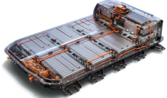
Electric vehicle batteries are built modularly, with the battery cells being the basic unit. Mul-tiple cells are combined into a battery module, and a battery pack contains several modules. Dismantling aims to bring the electric vehicle batteries from pack level to module level to allow for recycling.
The main goal of the thesis is to present a vision system capable of detecting and locating the parts of a battery pack. The vision system will be integrated with the robot controller, allowing the dismantling of parts to be verified and thus preventing damage to tools and parts. Two methods for object detection, template matching and You Only Look Once (YOLO), will be implemented, compared and evaluated to find the best method for the problem. A camera setup for the detection of the battery pack parts will also be presented.
2
Problem Formulation
Due to the uncertainty of end of life products, the battery packs to be dismantled can be of different models or different revisions of a model. This can result in battery packs that are similar on the outside but differ slightly on the inside, where one revision of a battery pack might have a part not existent in other versions. The battery packs might also have been opened and serviced which can result in screws or parts missing.
By integrating a vision system capable of detecting the battery pack parts and validating the status of dismantling with the robot controller, the part dismantling can be validated and damage to parts and equipment can be prevented. The detection of battery pack parts can also allow the robot controller to skip dismantling steps if a part is not in the battery pack, optimizing the dismantling and saving time.
In this master thesis, a vision system using two cameras will be designed and implemented. Two methods for object detection will be implemented and compared to find the best method. The vision system will compare the detected parts with the parts to be dismantled and communicate with the robot system. The implementation and testing will be limited to one battery pack model, and the position of the battery pack in the camera frame will be known.
The following research questions have been extracted from the problem formulation:
RQ1: How should the cameras be mounted to give a view of the battery pack parts that should be dismantled?
RQ2: How should the detected parts be matched with the components to be dismantled? RQ3: How should the solution be validated?
RQ4: Which object detector is best suited for the task based on precision, recall, time consumption and its ability to add new parts?
3
Background
This section will go through and give an overview of the object detectors used, evaluation metrics and some of the existing electric vehicle battery packs and their parts.
3.1
Template matching
Template matching is a digital image processing technique to find a known object or shape, a "template", in an image. It works by sliding the template across the image and calculating a score of how good the template matches the part of the image below it. By using a threshold on the match score, the template can be found in the image. An example where the symbol 2 is searched for in an image can be seen in Figure1.
There are multiple ways that the matching score between the template and the part of the image can be calculated. The most simple way is to compare the pixel values. However, if the object that should be detected is rotated in the image, there needs to exist a template for each rotation that the object is to be detected at. Keypoint matching and Ring Projection Transform are two template matching methods that solve that problem.
1 3 3 2 4 1 2 1 3 3 2 4 1 2 Image
Template Template sliding over image
Figure 1: Template matching example. 3.1.1 Keypoint matching
Keypoint matching is a method that can be used to match the template with the object in the image. It works by first calculating keypoints in both the template and image using a feature detector. The keypoints in the template is then matched with the keypoints in the image. Based on the number of matched keypoints it can be determined if the object in the template is present in the image. Some methods implementing versions of keypoint matching are capable of detecting rotated, scaled, transformed and partially occluded objects in the image [12]–[14].
3.1.2 Ring Projection Transformation
Ring Projection Transformation (RPT) [15] is a method for transforming a 2d matrix such as an image to a 1d vector. The ring projection vector RP T is composed of the pixel mean values P (r) on the circle of concentric circles with different radiuses. For the template or sliding window with size MxN, the center of the image is calculated by equation1. The maximum radius for the circle is calculated by equation2where the smallest side of the image is used to calculate the maximum radius. The RPT vector is calculated by equation3 where f(x, y) is the value of the pixel at x, y in the image. The maximum radius is Rmaxand P ixels(r) is the x, y indices for the pixels on the
circle with radius r, as seen in Figure2, and n(r) is the number of pixels.
The distance between the vector of the template and sliding window is used to determine if the object in the template is present in the image.
(
xcenter=int(N/2)
ycenter=int(M/2)
(1) Rmax=int(min(M − ycenter, N − xcenter)) (2)
RP T = [P (1), P (2), P (3), · · · , P (Rmax)]
P (r) = n(r)1 P f (Circle(r)) −min(f(Circle(r))), 0 < r < Rmax
Circle(r) = P ixels(r) + [xcenter, ycenter]
(3) 0 1 2 3 4 -1 -2 -3 -4 0 1 2 3 4 -1 -2 -3 -4 r = 1 r = 2 r = 3
Figure 2: The indices for the three first radii used for ring projection transform.
3.2
Convolutional Neural Network
Convolutional Neural Networks (CNN) [16] are a type of neural networks designed to process data in the form of matrices, such as images. A CNN normally contains three types of layers: convolutional, pooling and a fully connected layer. A simple example of a CNN architecture can be seen in Figure3. The number of layers and how they are arranged can vary between different CNN implementations.
Feature maps
Feature maps Feature maps Feature maps Input image
Convolution Pooling Convolution Pooling Fully connected Flatten Output
Figure 3: Architecture of a simple CNN
The purpose of the convolutional layer is to extract information from the image. This is achieved by convolution between the input image and a kernel, which is spatially small but has the same depth as the image. The results from the convolution is a 2D feature map. An example of convolution between a kernel and an image with depth one is show in Figure 4. A convolutional layer can have multiple kernels resulting in the output from the layer being width_out × height_out × nr_kernels.
Kernel
Image
Convolution output
Figure 4: Convolution example.
The pooling layer reduces the spatial size of the image representation by scaling it down. This can be done by either max pooling or average pooling. Max pooling returns the maximum value of
a part of the image while average pooling returns an average of the values for a part of the image. Figure5shows max and average pooling for an image.
2 4 6 1 14 4 10 9 3 7 8 6 3 8 6 5 10 15 12 11 10 14 8 8 Average pooling Max pooling
Figure 5: Max and Average pooling on an image.
For the fully connected layer, each neuron is connected to to all neurons in the previous layer. This means that the image can be flattened into a column vector that is the input to the fully connected layer. The fully connected layer outputs the class of the object detected in the image. 3.2.1 Training neural networks
When training neural networks, the input is feed through the entire network and the loss, which is the difference between the predicted and the true value, is calculated. Then the gradient of the loss function is calculated with respect to the network’s weights and the weights are updated using the gradient. This is done multiple times until the loss is reduced to a desired level. The training of neural networks can take a long time, and the bigger the network is, the longer time it will take. 3.2.2 Transfer learning
Transfer learning is when a pre-trained network is used as the starting point for another network. This works when the pre-trained network was trained on a large dataset with many classes. Transfer learning allows the learned features of the pre-trained network to be transfer to a new network that will be trained on another dataset, reducing the time needed to train the network.
3.3
YOLO
You Only Look Once (YOLO) is an object detector created by Redmon et al. [17] that have received multiple updates [18]–[20]. YOLO is based on a convolutional neural network and consists of a number of hidden layers. YOLOv4 has a network that consists of three parts, a backbone, a neck and a head, where each part consists of multiple layers of different type and sizes. The backbone is a convolutional neural network and is used to extract features from the image. The role of the neck is to collect feature maps from different stages of the network and the head performs dense prediction based on the detected features. This is the final prediction which is composed of a vector containing the coordinates of the predicted bounding box, the confidence score of the prediction and the label.
YOLOv4 uses the neural network CSPDarknet53 for the backbone. A Spatial Pyramid Pooling (SPP) [21] layer and a Path Aggregation Network (PAN) [22] for the neck, and YOLOv3 as the head.
3.4
Evaluation
Based on the predicted and the actual class, a confusion matrix such as the one in Figure6 can be used to divide the detections into true positive, false positive, false negative and true negative detections. Precision and recall are two metricise for evaluating detections based on the confusion matrix. Precision is calculated by equation4and measures the number of true positive detections over the total positive detections. Recall is calculated by equation5 and is the number of true class detections over the number of possible detections of that class.
Figure 6: Confusion matrix
P recision = T P
T P + F P (4)
Recall = T P
T P + F N (5)
3.5
Battery pack models and parts
There are several battery pack models and they vary in size, vary in components and layout depending on the manufacturer and car model. However, common to all models is that the battery consists of multiple modular parts, where the battery pack is the outermost casing attached to the vehicle. Inside the battery pack, there is a cooling system, a battery management system (BMS) and multiple battery modules. Each battery module contains multiple battery cells that are either cylindrical, prismatic or pouches.
BMW i3 The BMW i3 battery pack contains eight battery modules that are placed on top of a cooling system that runs along the bottom of the battery pack, cooling the modules from the underside [23]. The modules are connected together in series via high voltage cables. The cables are permanently connected to the positive terminal of the module and has a connector at the other end, whereas the left terminal on the module has a matching connector. The battery pack also contains a main BMS and a power conversion system. Figure7shows the battery pack.
Figure 7: The BMW i3 battery pack.
Chevrolet Bolt The Chevrolet bolt battery pack contains ten battery modules, where the mod-ules are placed two in a row, spanning the width of the battery pack [24]. Eight of the battery modules are placed on the bottom, and two smaller modules are placed in a row on top of the modules at the back of the pack, see Figure8. The batteries are connected via bus bars. Cooling of the battery modules are handled by cooling plates placed under the modules. Power relays are mounted in the front of the pack and a BMS is mounted on top of the back battery modules and is connected via wires to the battery modules.
Figure 8: Chevrolet Bolt battery pack. Attribution: Chevrolet, CC BY-NC 3.01, via Chevrolet
Media2
Nissan LEAF The Nissan LEAF battery pack has two different battery module shapes with different numbers of cells. Figure 9 shows that there is one big module at the back, and two smaller modules at the front with two stacks of cells [25]. Unlike the other battery packs using liquid cooling, it uses air channeled from the heating and ventilation system in the car to cool or warm the battery [26]. The modules are connected together using bus bars and are also wired to a BMS.
Figure 9: Nissan Leaf battery pack. Attribution: Gereon Meyer, CC BY-SA 4.03, via Wikimedia
Commons4
These battery packs all contain battery modules of different sizes, however they all have a rectangular shape. Common for the battery packs are that the high voltage conductors connecting the battery modules, be it wires or bus bars, are colour coded orange. The battery packs also contain a main BMS that is connected to the battery modules BMS. The final difference between the pack components is the cooling system. One model use air cooling while the two other models use liquid cooling.
1https://creativecommons.org/licenses/by-nc/3.0/
2https://media.chevrolet.com/media/us/en/chevrolet/photos.detail.html/content/media/us/en/
chevrolet/vehicles/bolt-ev/2017/_jcr_content/rightpar/galleryphotogrid.html
3https://creativecommons.org/licenses/by-sa/4.0
4
Related Work
An architecture for a vision-based automated disassembly system of batteries was proposed by Weyrich and Wang [27]. Their solution is to use a vision system to detect the part being dismantled and identify it with the help of a database. The database contains information about the part assembly and its space constraints. The disassembly sequence and robot path are determined by fusing the object detection with the database. Their proposed architecture requires detailed information from the manufacture of the product that might not be available. Including detailed product information, CAD model and assembly information.
4.1
Template matching
Another method for detecting objects in images is using template matching. Qi and Miao [28] proposed a method for multi-scale and rotated image template matching. The ring projection vector is calculated of the template, and ring vector conversion is used to scale the template. The similarity between the new ring projection vector and the ring projection vector of each point of the scene image is calculated by normalized cross-correlation.
Dai et al. [29] presented a framework for visual tracking. Their framework fuses the response maps from a convolutional template matching framework, and a convolutional foreground detection network. A pre-trained VGG network is used as a feature extractor and shared by the foreground detection and template matching. The use of a trained network limits detection to the pre-trained objects, otherwise the advantage of not needing a large set of training data is lost.
A method using mutual nearest neighbours for robust template matching was described in a paper by Oron et al. [14]. They introduce a similarity measure named Best-Buddies Similarity (BBS), which measures the similarity between two point sets. BBS consider two points that are mutual nearest neighbours to be a Best-Buddies Pair (BBP). The BBPs are used to find the template in the target image. The tests performed by Oron et al. showed that using BBS, the template could be found even when the object in the target image had large geometric deformation and background clutter.
A real-world implementation of template matching for automated disassembly was presented by Schumacher and Jouaneh [7]. They used template matching to determine the location and type of device for the automated disassembly of snap-fit covers to remove AA batteries from household electronics.
An implementation of screw detection using template matching was proposed by Cruz-Ramirez et al. [30]. They used a stereo camera mounted on a robot arm to locate and follow a steel beam, and template matching in 2D to detect the screws. Their results showed that adequate lighting and threshold values could give a good detection ratio.
4.2
Neural networks
The use of neural networks for object detection and classification have been heavily researched in recent years. This has resulted in a verity of different networks such as Faster R-CNN by Ren et al. [31], You only look once (YOLO) by Redmon et al. [17] and Single Shot MultiBox Detector (SSD) by Liu et al. [32].
While neural networks are not commonly used in dismantling, they are more frequently used in assembly tasks and for validation and inspection of assemblies, which is similar. An automated contact assembly was presented in a paper by Li et al. [33]. They used a vision feedback system based on YOLO to detect and locate multiple objects and the working tool. The camera was mounted to give a top-down view. Their results showed that their method was effective and allowed for an automated assembly.
Li et al. [34] demonstrated the usefulness of YOLO V3 for the task of detecting electronic components on PCBs. They used YOLO V3 on RGB images to detect various sized surface mounted components on different PCBs. Their tests showed that YOLO V3 had a good detection speed and detection results. Similarly, Lin et al. [35] used YOLO to inspect capacitors during PCB manufacturing. They trained the network on nine types of capacitors and results showed that the detection time for an image was 0.3 seconds, and therefore applicable in manufacturing lines.
To minimize manual inspection mistakes, and allow for visual and intuitive guidance in tra-ditional manufacturing assembly, Wang et al. [36] proposed a Faster R-CNN and mixed reality approach using the HoloLens mixed reality headset. They trained the network to detect parts in the assembly and results showed a mean average precision of about 85%. The HoloLens was used to take the images, and to show information of the detected assembly parts to the user. Zidek et al. [37] also presented an implementation of R-CNN to speed up assembly processes with augmented devices. They trained the network on parts and features in the assembly and tests showed premising results. They noted that the learning process was time-consuming, but that the achieved level of robustness and invariability is better than with standard image processing techniques. They stated that the main problem was the detection of overlapping parts and parts with shiny surfaces.
Monitoring of human-based assembly using R-CNN was proposed by Andrianakos et al. [38]. The R-CNN network was trained on the parts of the assembly and used to detect and locate the parts. The location of the parts were used to determine if the correct assembly step was done by the human.
Yildiz and Wörgötter [10] proposed a model for screw detection in disassembly environments. Their scheme requires a setup where the camera is mounted facing the devices surface perpendicu-larly. The detection model combines the Hough transform and deep neural networks. The Hough transformation was used to detect screw candidates. Then two neural networks, InceptionV3 and Xception, were used to classify the screw candidates. The final prediction is a weighted sum of the two neural networks predictions. The model proposed by Yildiz and Wörgötter showed higher accuracy then other tested neural networks trained on the same data.
The performance of YOLO V4, Raster R-CNN and SSD was compared in a paper by Kim et al. [39]. The networks were trained on the same data consisting of six vehicle types. Their results showed that SSD was the fastest, followed by YOLO and then R-CNN. However, YOLO showed the highest precision and SSD had the lowest.
4.3
Classic computer vision methods
A shape recognition system for automated disassembly of tv sets was described in a paper by Jorgensen et al. [8]. They used a 2D camera and 3D sensor, multiple pre-processors and a neural network to classify the tv parts. They used gradient information, several local depth histograms and basic shapes detected by a template matching algorithm as pre-processors. The output from the pre-processors was fed into the neural net. The multiple pre-processors allow the trained neural network to use the most reliable information to detect the features, but it is highly dependant on the quality of the pre-processing.
Gil et al. [40] presented a method to detect partial occlusion of assembled components. The proposed method implements multi-threshold segmentation on both RGB and HSV colour space. The combined information from the two colour spaces, together with edge detection, is used to detect overlapping and partial occlusion. They noted that the RGB-HSV segmentation performs better than when segmentation is done in only RGB or HSV space.
An computer vision algorithm for detecting motor screws, to automate electric motor disas-sembly, was proposed by Bdiwi et al. [41]. They used a Kinect camera, placed above the motor looking straight down, to acquire image and depth data. A Harris detector extracted feature points, and the HSV values of the image were used to remove false positives. The remaining feature points were turned into segments using a region growing algorithm. Further false positives were removed by examining the ratio of the regions on the major axis and the depth data. Due to noisy depth values, the average of screw detections over multiple images was used to produce stable screw locations. They noted that their algorithm worked better on shiny screws and that rusty screws with no colour variation were undetected. Their algorithm is scale, rotation and translation invari-ant. However, the Harris corner detection and HSV values can be easily affected by the lighting condition. The requirement of a depth image also adds computational load.
4.4
State of art summary
For the dismantling of the battery pack, an object detector with good detection results is needed to provide a safer dismantling. The related works show that classical computer vision methods are more susceptible to changes in lighting which are common in an environment with large moving robots. Neural networks have shown good detection results in varying environments with the added benefit of being fast. The downside of neural networks is that they need a dataset of labelled images to train on and the training takes time. The advantages of template matching are that it does not require a labelled dataset, and does not need to be trained. If the implementation of template matching uses either ring projection vectors or keypoint matching, a single template is required to find objects even when rotated. The downside of template matching is that it is slower than neural network solutions.
Therefore the neural network YOLOv4 and template matching using ring projection transform-ation and keypoint matching will be investigated further for the task.
5
Method
This section describes the research methodology used for this thesis as well as the method used to evaluate the object detectors.
5.1
Research Methodology
The methodology followed in this thesis is the iterative design process described by Tayala [42]. The method consists of eight steps, and they span from identifying a problem or need to the creation and development of a solution. The engineering design process is iterative and moving back to previous steps is normal. By going back to a previous step, the design process iterates forwards, by solving problems and testing new solutions before ending on a final design. The eight steps of the iterative engineering process are:
• Define the Problem
In this step, the problem and what is to be done should be defined. The project requirements and limitations are also defined.
• Do Background Research
This involves a literature study to investigate what has been done in the field and in related fields to learn from the experience of others.
• Specify Requirements
Design requirements state the important characteristics that the solution must meet to suc-ceed. This can be done by analyzing similar, existing implementations or products, noting their key features.
• Brainstorm Solutions
This step aims to find many possible solutions. This helps avoid focusing on one solution before looking at alternative solutions.
• Choose the Best Solution
Based on the needs identified and information and experience gathered from the background research, the best solution is chosen.
• Do Development Work
The development of the chosen solution. This involves refinements and improvements to the solution and can occur over multiple iterations.
• Build a Prototype
In this step an operating version, a prototype, of the solution is constructed. It is a key step in the development of a final solution, allowing the solution to be tested and find out how it works.
• Test and Redesign
The step focuses on testing the design to find problems and make changes and the design process often involves multiple iterations and redesigns of the final solution.
5.2
Evaluation
To validate the two object detection methods, they will be used to detect battery pack parts in the images from a test dataset captured from the cameras during different steps of the dismantling sequence. The precision and recall for the different parts from the object detectors will be com-pared. An evaluation of the execution time will also be performed for both the object detection methods.
6
Ethical and Societal Considerations
Electric vehicles move us towards a more sustainable life regarding fossil fuel usage. However, the manufacturing of electric batteries is not free from CO2 emissions. The metals used in the manu-facturing has to be mined, processed and transported, which is environmentally heavy operations. This work could help to improve the safety of automated disassembly, thus helping to provide a good recycling capacity for car batteries. Which allows for the valuable metals to be recovered and used again, lowering the need to mine new materials. Thus moving towards more ecologically sustainable development.
A system that helps provide an automated dismantling of the battery packs also provide a safer work environment as the workers do not have to lift or handle the heavy high voltage batteries.
7
System design
This section presents the main system elements, the camera placement, software used as well as the system architecture.
7.1
Main system elements
The battery pack is dismantled inside a robot cell with the battery pack fixed in a workstation. The robot is an IRB 7600-500 and is controlled by an IRC5 controller. The vision system runs on a computer with 16 GB RAM, an i5-6300HQ processor and a GeForce GTX960m graphics card. The two cameras for the vision system use the 16 megapixel Sony IMX298 sensor [43].
7.2
Camera placement
The vision system uses two cameras that are mounted to provide a view of the battery pack parts that should be dismantled. To achieve this, one camera is mounted above the battery pack and one on the robot arm, see Figure 10. The camera placed above the battery is centred along its length but off to the side. This allows it to see the larger parts in the battery pack while still being out of the way for the robot. The second camera is mounted on the robot arm which allows it to see the smaller parts without them getting to small. Because the camera moves with the robot it is able to see parts located at the bottom of the battery pack in narrow places.
Figure 10: Camera setup in the robot cell.
7.3
Software and communication
The software and communication methods used for the system. 7.3.1 Robotstudio
To speed up development and make the testing of the robot controller and vision system safer a simulated robot controller was used. The real world robot controller and the robot cell was simulated using Robotstudio5. Robotstudio was also used to configure and program the controller
using the RAPID programming language. The robot controller acts as a client and connect to the vision system.
7.3.2 Python
The vision system is built on Python and acts as the server. On requests from the robot system it captures an image, performs object detection and match the detected battery parts to the part that should be dismantled.
5
7.3.3 Communication
The communication between the simulated robot controller in Robotstudio and the vision system is done using TCP/IP sockets over a Local Area Network (LAN). Where the IP and port numbers of the robot controller and vision system are used by the sockets.
The vision system acts as a server, it creates a socket and listens for incoming connect requests from clients. The robot controller acts as a client and sends a connection request to the vision system. When the vision system accepts the connection request from the robot controller, messages can be sent between them.
8
Implementation
This section aims to describe the datasets created and used, the implementation of the object de-tection methods, YOLOv4 and Template matching. As well as the matching of the part dede-tections to the part that should be dismantled.
8.1
Datasets
Two datasets were created, one for training the YOLOv4 network and the other for testing the objectdetectors.
8.1.1 YOLOv4 Dataset
The dataset used to train YOLOv4 was collected by taking videos of the battery pack parts while moving the camera to capture the battery parts from different angles and distances. The videos were labelled using the Computer Vision Annotation Tool (CVAT)6.
Using image augmentation, an augmented version of each image was created, doubling the size of the dataset and increasing the image variety. The augmentation tool Albumentations [44] was used to perform the augmentations. Each augmented image had an 80% chance to be flipped vertically, 50% chance of getting a random brightness, was randomly scaled down by a factor between 0.5 and 1, and finally had a 50% chance to be rotated between −90, 90 deg.
The dataset consists of 20550 training images and 3800 validation images, where half of the images in both sets are augmented images.
8.1.2 Testing dataset
To test the object detectors, a dataset containing images from the two cameras during different dismantling steps were gathered. The dataset has 15 images from the top-down camera showing the battery lid, and another 15 images when the lid is removed. From the robot camera there are 15 images of the bracket bolts, and another 15 of the lid screws and nuts.
8.2
Object detection
Two different object detection methods were implemented and compared, YOLOv4 and template matching. For template matching, two different matching methods were implemented.
8.2.1 YOLOv4
The tiny version of YOLOv4, YOLOv4-tiny, was implemented and compiled in C, and the vision system written in Python uses a Python wrapper to interface with the C code. This was done to benefit from the speed of the C language.
The network was trained using weights that were pre-trained on the MS COCO [45] dataset as the initial weights. The dataset used to train the network was created from images of the battery pack parts.
8.2.2 Template matching
To test template matching, two different approaches to template matching were implemented and compare. The first approach uses keypoint matching to match the template and sliding window while the second approatch uses Ring Projection Transform (RPT). Both methods compute a matching score between the template and the sliding window that moves across the scene image, where both the template and scene image are grayscale images.
Because multiple neighbouring sliding windows can have a score above the threshold and be potential matches, they need to be filtered to remove duplicate matches for the same part. Using non-max suppression the matches with the best score are kept while matches that overlap more than a threshold are removed.
8.2.3 Keypoint matching
The ORB [46] feature detection algorithm was used to detect keypoints in the template images and the sliding windows. The detected keypoints from the template were matched with the detected keypoints from the sliding window using the Fast Library For Approximate Nearest Neighbors (FLANN) [47]. If the number of matched keypoints exceeds a threshold the sliding window is considered a possible match.
8.2.4 Ring Projection Transform
The Ring Projection Transform was implemented based on [15] and creates a vector of the template and sliding window by calculating the mean average of the pixel values for each radii of a circle centered in the image.
To reduce computation time, the pixel indices for each radius of a circle centered at zero are pre-calculated and stored in a lookup table. This makes the indexes for each image easy to calculate by simply adding the x, y values for the center of the image to the pre-calculated indices.
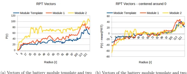
The RPT vectors of the templates and sliding windows are then zero meaned, see Figure11. This allows for bigger differences in illumination of the parts in the image compared to the tem-plates.
The Euclidean distance between the template vector and window vector determine if the tem-plate matches the sliding window. Because lower distances indicate better matches, distances below the threshold are considered possible matches.
(a) Vectors of the battery module template and two battery modules
(b) Vectors of the battery module template and two battery modules after zero mean.
Figure 11: RPT vectors of the battery module template and two modules before and after zero mean.
8.3
Detection matching
Based on the detections from the object detector, the vision system should determine if the part is in the battery pack or not. Therefore it must check if one of the detections is the part. This is done by checking each detection to see if it has the same class as the part and that the center of the detection lies within a radius of the parts known location. The parts known location and the radius threshold are defined in the part list loaded by the vision system. If one of the detections has the correct class and has its center located within the radius, the part is in the battery pack. Figure12. illustrates a part detection with its center within the radius centred on the parts position.
Part located in image
Radius centerd on known part location Detection
Figure 12: Detection matching using radius threshold.
8.4
Robot controller software
9
Results
This section presents the results for the YOLOv4 and the two template matching methods, Ring Projection transform and keypoint matching. The results of the communication between the simulated robot controller and the vision system is also presented.
9.1
YOLOv4
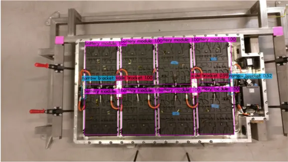
The battery pack lid, battery modules, wide and narrow brackets are detected using the camera mounted above the battery pack, providing a top-down view. The detection of the battery pack lid can be seen in Figure13, and the battery modules together with the wide and narrow brackets are detected in Figure14.
Figure 13: YOLOv4 Detection of the battery pack lid.
From the robot camera image the bracket bolts, lid screws and nuts are detected. In Figure15
the detection of the bracket bolts holding down a wide bracket are shown, and Figure 16shows the detections of the nuts and lid screws.
Figure 15: YOLOv4 Detection of the bracket bolts.
Figure 16: YOLOv4 Detection of lid screws and nuts.
YOLOv4 was tested on the test dataset with 15 images of each battery pack part and the detection results for the different parts are compiled in Table1. The table shows the number of true positive, false positive and false negative detections of the parts in the test dataset. The calculated precision and recall for the parts are also shown together with the mean execution time for the network to detect the parts in the 15 images.
Table 1: YOLOv4 Detection results of the battery pack parts. YOLO part detection
Part TP FP FN Precision Recall Time [S]
Lid 15 0 0 1 1 0.071 Module 120 0 0 1 1 0.071 Wide bracket 30 0 0 1 1 0.071 Narrow bracket 24 0 6 1 0.8 0.071 Bracket bolt 60 4 0 0.938 1 0.071 Lid screw 90 0 0 1 1 0.071 Nut 71 1 3 0.986 0.959 0.071
9.2
Template matching - Ring projection transform
The detection of parts using RPT was tested on the full sized images from both cameras as well as cropped images, where the image from the camera mounted above the battery pack is cropped to the battery pack and the robot camera image is cropped to the area below the robot tool. 9.2.1 Part detection in full images
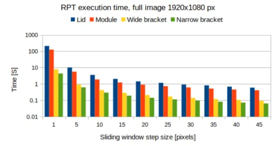
The execution time for the detections of the lid, battery modules, wide and narrow brackets for different sliding window step sizes in the full 1920x1080 pixel image from the camera mounted above the battery pack is shown in Figure 17. Where the execution time is the mean time for detecting the parts in 15 images. The detection results for the lid, battery module, wide and narrow brackets for the different step sizes are shown in Table2-5respectively. The tables contain the number of true positive, false positive and false negative detections of the parts in the test dataset for different step sizes, as well as the calculated precision and recall for the parts. The detections of the lid, battery modules, wide and narrow brackets with their max step size, without loosing precision and recall, are shown in Figure18-21.
Table 2: RPT Detection of the lid in the full im-age.
Lid
Step TP FP FN Precision Recall
1 15 0 0 1 1 5 15 0 0 1 1 10 15 0 0 1 1 15 15 0 0 1 1 20 15 0 0 1 1 25 15 0 0 1 1 30 15 0 0 1 1 35 15 0 0 1 1 40 0 0 15 0 0 45 0 0 15 0 0
Figure 18: RPT detection of the lid in a full image with the best step size.
Table 3: RPT Detection of modules in the full image.
Module
Step TP FP FN Precision Recall
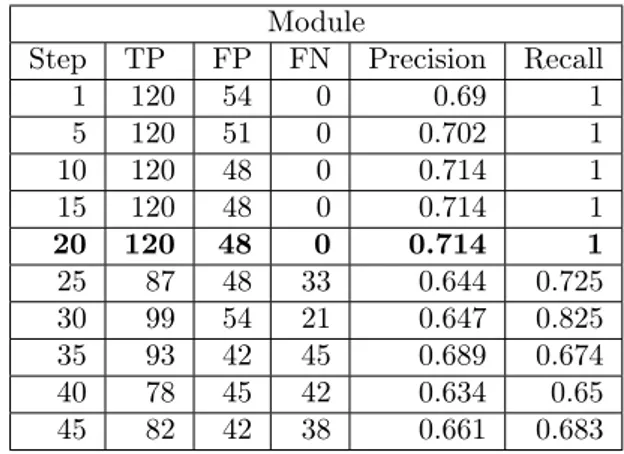
1 120 54 0 0.69 1 5 120 51 0 0.702 1 10 120 48 0 0.714 1 15 120 48 0 0.714 1 20 120 48 0 0.714 1 25 87 48 33 0.644 0.725 30 99 54 21 0.647 0.825 35 93 42 45 0.689 0.674 40 78 45 42 0.634 0.65 45 82 42 38 0.661 0.683
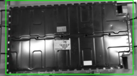
Figure 19: RPT detection of modules in a full image with the best step size.
Table 4: RPT Detection of wide brackets in the full image.
Wide bracket
Step TP FP FN Precision Recall
1 27 0 3 1 0.9 5 0 0 30 0 0 10 0 0 30 0 0 15 0 0 30 0 0 20 0 0 30 0 0 25 0 0 30 0 0 30 0 0 30 0 0 35 0 0 30 0 0 40 0 0 30 0 0 45 0 0 30 0 0
Figure 20: RPT detection of wide brackets in a full image with the best step size.
Table 5: RPT Detection of narrow brackets in the full image.
Narrow bracket
Step TP FP FN Precision Recall
1 9 0 21 1 0.3 5 0 0 30 0 0 10 0 0 30 0 0 15 0 0 30 0 0 20 0 0 30 0 0 25 0 0 30 0 0 30 0 0 30 0 0 35 0 0 30 0 0 40 0 0 30 0 0 45 0 0 30 0 0
Figure 21: RPT detection of narrow brackets in a full image with the best step size. The execution time for detecting bracket bolts, lid screws and nuts in the full image from the robot camera with different sliding window step sizes is shown in Figure22. Where the execution time is the mean time for detecting the parts in 15 images. The detection results for the bracket bolt, lid screw and nut for the different step sizes are shown in Table6-8 respectively. The tables contain the number of true positive, false positive and false negative detections of the parts in the test dataset for different step sizes, as well as the calculated precision and recall for the parts. The detections of the bracket bolts, lid screws and nuts with their max step size, without loosing presicion or recall, are shown in Figure23-25respectively.
Table 6: RPT Detection of bracket bolts in the full image.
Bracket bolt
Step TP FP FN Precision Recall
1 6 156 54 0.037 0.1 5 0 0 60 0 0 10 0 0 60 0 0 15 0 0 60 0 0 20 0 0 60 0 0 25 0 0 60 0 0 30 0 0 60 0 0 35 0 0 60 0 0 40 0 0 60 0 0 45 0 0 60 0 0
Figure 23: RPT detection of bracket bolts in a full image with the best step size.
Table 7: RPT Detection of lid screws in the full image.
Lid screw
Step TP FP FN Precision Recall
1 15 99 75 0.132 0.167 5 0 7 90 0 0 10 0 7 90 0 0 15 0 0 90 0 0 20 0 0 90 0 0 25 0 0 90 0 0 30 0 0 90 0 0 35 0 0 90 0 0 40 0 0 90 0 0 45 0 0 90 0 0
Figure 24: RPT detection of lid screws in a full image with the best step size.
Table 8: RPT Detection of nuts in the full image. Nut
Step TP FP FN Precision Recall
1 9 99 66 0.083 0.12 5 0 0 75 0 0 10 0 0 75 0 0 15 0 0 75 0 0 20 0 0 75 0 0 25 0 0 75 0 0 30 0 0 75 0 0 35 0 0 75 0 0 40 0 0 75 0 0 45 0 0 75 0 0
Figure 25: RPT detection of nuts in a full image with the best step size.
Table9shows the best detection results for all parts in the full images of the test dataset with respect to their step size, precision and recall. The table shows the parts maximum step size, the number of true positive, false, positive and false negative detections, the calculated precision and recall as well as the mean execution time for that step size.
Table 9: Best RPT part detections on the full images. Best RPT part detection results on the full images
Part Step size TP FP FN Precision Recall Time [S]
Lid 35 15 0 0 1 1 0.824 Module 20 120 48 0 0.714 1 0.912 Wide bracket 1 27 0 3 1 0.9 7.967 Narrow bracket 1 9 0 21 1 0.3 4.365 Bracket bolt 1 6 156 54 0.037 0.1 9.347 Lid screw 1 15 99 75 0.132 0.167 6.369 Nut 1 9 99 66 0.083 0.12 4.876
9.2.2 Part detection in cropped images
The execution time for the detections of the lid, battery modules, wide and narrow brackets for different sliding window step sizes in the top-down camera view when the image is cropped to the battery pack is shown in Figure26. Where the execution time is the mean time for detecting the parts in 15 images. The detection results for the lid, battery module, wide and narrow brackets for the different step sizes are shown in Table10-13respectively. The tables contain the number of true positive, false positive and false negative detections of the parts in the test dataset for different step sizes, as well as the calculated precision and recall for the parts. The detections of the lid, battery modules, wide and narrow brackets with their max step size, without loosing precision and recall, are shown in Figure27-30.
Figure 26: RPT Execution time for the parts detected in the cropped image from the top-down camera.
Table 10: RPT Detection of the lid in the cropped image.
Lid
Step TP FP FN Precision Recall
1 15 0 0 1 1 5 15 0 0 1 1 10 15 0 0 1 1 15 15 0 0 1 1 20 15 0 0 1 1 25 15 0 0 1 1 30 15 0 0 1 1 35 0 0 15 0 0 40 0 0 15 0 0 45 0 0 15 0 0
Figure 27: RPT detection of the lid in a cropped image with the best step size.
Table 11: RPT Detection of modules in the cropped image.
Module
Step TP FP FN Precision Recall
1 120 0 0 1 1 5 120 0 0 1 1 10 120 0 0 1 1 15 120 0 0 1 1 20 120 0 0 1 1 25 99 0 21 1 0.825 30 96 0 24 1 0.8 35 90 0 30 1 0.75 40 84 0 36 1 0.7 45 78 0 42 1 0.65
Figure 28: RPT detection of modules in a cropped image with the best step size.
Table 12: RPT Detection of wide brackets in the cropped image.
Wide bracket
Step TP FP FN Precision Recall
1 27 0 3 1 0.9 5 15 0 1 5 1 0.5 10 15 0 15 1 0.5 15 0 0 30 0 0 20 15 0 15 1 0.5 25 0 0 30 0 0 30 0 0 30 0 0 35 0 0 30 0 0 40 0 0 30 0 0 45 0 0 30 0 0
Figure 29: RPT detection of wide brackets in a cropped image with the best step size.
Table 13: RPT Detection of narrow brackets in the cropped image.
Narrow bracket
Step TP FP FN Precision Recall
1 9 0 21 1 0.3 5 0 0 30 0 0 10 0 0 30 0 0 15 0 0 30 0 0 20 0 0 30 0 0 25 0 0 30 0 0 30 0 0 30 0 0 35 0 0 30 0 0 40 0 0 30 0 0 45 0 0 30 0 0
Figure 30: RPT detection of narrow brackets in a cropped image with the best step size. The execution time for detecting bracket bolts, lid screws and nuts at different step sizes in the robot camera image cropped to the area below the robot tool is shown in Figure 31. Where the execution time is the mean time for detecting the parts in 15 images. The detection results for the bracket bolt, lid screw and nut for the different step sizes are shown in Table 14-16 respectively. The tables contain the number of true positive, false positive and false negative detections of the parts in the test dataset for different step sizes, as well as the calculated precision and recall for the parts. The detections of the bracket bolts, lid screws and nuts with their max step size, without loosing presicion or recall, are shown in Figure32-34respectively.
Table 14: RPT Detection of bracket bolts in the cropped image.
Bracket bolt
Step TP FP FN Precision Recall
1 9 21 51 0.3 0.15 5 0 3 60 0 0 10 0 3 60 0 0 15 0 0 60 0 0 20 0 3 60 0 0 25 0 0 60 0 0 30 0 0 60 0 0 35 0 0 60 0 0 40 0 0 60 0 0 45 0 0 60 0 0
Figure 32: RPT detection of bracket bolts in a cropped image with the best step size.
Table 15: RPT Detection of lid screws in the cropped image.
Lid screw
Step TP FP FN Precision Recall
1 21 30 24 0.412 0.467 5 0 0 45 0 0 10 0 0 45 0 0 15 0 0 45 0 0 20 0 0 45 0 0 25 0 0 45 0 0 30 0 0 45 0 0 35 0 0 45 0 0 40 0 0 45 0 0 45 0 0 45 0 0
Figure 33: RPT detection of lid screws in a cropped image with the best step size.
Table 16: RPT Detection of nuts in the cropped image.
Nut
Step TP FP FN Precision Recall
1 9 45 21 0.167 0.3 5 0 0 30 0 0 10 0 0 30 0 0 15 0 0 30 0 0 20 0 0 30 0 0 25 0 0 30 0 0 30 0 0 30 0 0 35 0 0 30 0 0 40 0 0 30 0 0 45 0 0 30 0 0
Figure 34: RPT detection of nuts in a cropped image with the best step size. Table17shows the best detection results for all parts in the cropped images of the dataset with respect to their step size, precision and recall. The table shows the parts maximum step size, the number of true positive, false, positive and false negative detections, the calculated precision and recall as well as the mean execution time for that step size.
Table 17: Best RPT part detections on the cropped images. Best RPT part detection results on the cropped images
Part Step size TP FP FN Precision Recall Time [S]
Lid 30 15 0 0 1 1 0.073 Module 20 120 0 0 1 1 0.572 Wide bracket 1 27 0 3 1 0.9 4.202 Narrow bracket 1 9 0 21 1 0.3 2.596 Bracket bolt 1 9 21 51 0.3 0.15 2.768 Lid screw 1 21 30 24 0.412 0.467 2.353 Nut 1 9 45 21 0.167 0.3 1.998
9.3
Template matching - keypoint matching
The keypoint matching of the lid in one of the cropped test image from the top-down camera with a sliding window step size 30 is shown in Figure35. The detection of the battery modules in one test image with a sliding window step size of 15 is shown in Figure36. The figure shows the battery module detections with and without an increased threshold. The detection of wide brackets, narrow brackets, baracket bolts, lid screws, and nuts with a sliding window step size of 1 are shown in Figure37-41 respectively, which are images from the test dataset. The figures contain two images, the first show the detections with the set threshold, and the second shows the detections with an increased threshold to reduce false positive matches.
Figure 35: Keypoint matching detection of the lid.
(a) Battery module detection (b) Battery module detection with increased threshold.
Figure 36: Keypoint matching detection of the battery modules.
(a) Detection of the wide brackets.
(b) Detection of the wide brackets with increased threshold. Figure 37: Keypoint matching detection of the wide brackets.
(a) Detection of the narrow brackets.
(b) Detection of the narrow brackets with increased threshold. Figure 38: Keypoint matching detection of the narrow brackets.
(a) Detection of the bracket bolts. (b) Detection of the bracket bolts with in-creased threshold.
Figure 39: Keypoint matching detection of the bracket bolts.
(a) Detection of lid screws (b) Detection of lid screws with increased threshold.
(a) Detection of nuts (b) Detection of nuts with increased threshold.
Figure 41: Keypoint matching detection of nuts.
The true positive, false positive and false negative detections for the parts when detected on the test dataset are shown in Table 18, together with the calculated precision and recall. The mean execution time for the detections are also shown. However, the execution times are for when the detection is run only on the CPU, and it should be noted that the wide and narrow bracket detections are performed on images cropped to only include the middle of the battery pack.
Table 18: Keypoint matching part detections on the cropped images. Keypoint matching: best part detection results on the cropped images
Part Step size TP FP FN Precision Recall Time [S]
Lid 30 15 0 0 1 1 26.535 Module 15 100 9 20 0.917 0.833 316.612 Wide bracket 1 26 305 4 0.079 0.867 572.964 Narrow bracket 1 25 509 5 0.047 0.833 116.127 Bracket bolt 1 3 897 57 0.003 0.05 422.117 Lid screw 1 3 861 42 0.003 0.067 194.036 Nut 1 2 144 28 0.014 0.067 117.977
9.4
System communication
The console logs from the simulated robot controller and vision system for the dismantling of the first three lid screws can be seen in AppendixA. The logs show the successful initialization of the vision system and the part detections before and after the disassembly step. The second screw had already been removed, stopping the system until the user allowed it to continue.
10
Discussion
With one camera above the battery pack and one on the robot arm, all the battery pack parts could be captured by the cameras. The placement of the top-down camera allowed it to capture the big battery pack parts, and the camera mounted on the robot arm allowed for closer images of the smaller parts. The fact that the camera could move with the robot contributed to provide a better view of the nuts and smaller parts placed in the bottom of the battery pack.
The detection results for the compared object detection methods running on the testing dataset, showed that the YOLOv4 tiny detector presents the best results for the studied application in terms of precision, recall and execution time for the different parts. However, some misdetections recognizing the narrow brackets, bracket bolts and nuts were also shown. It has been observed that using the tiny version of YOLOv4, which is composed of 29 layers instead of the 137 layers in the full network, reduces the execution time as well as the training times with the downside of having an accuracy loss. The tiny network was used because the graphics card did not have enough video memory to train the full YOLOv4 network. With a more powerful GPU, the full network could have been trained, increasing the accuracy of the detections. Additionally, the detection could also have been improved by adding more images of the misdetected parts in the training dataset.
For the template matching method, cropping the image to the area of interest reduced the execution time and also removed the false positive detections outside the battery pack. For the top-down camera, the image was cropped to the battery pack and for the robot camera, the image was cropped to the area below the robot tool.
Template matching with RPT showed good precision and recall for the lid and the battery modules on the cropped images. However, the smaller parts were more prone to false positive and false negative detections. When the images are converted to vectors, the smaller templates are converted to shorter vectors, making it harder to distinguish between the part and other areas of the image. To help with the varying lightning conditions the zero mean of the vectors is used. This method causes that the sliding windows with similar pixel intensity changes will then be considered possible matches despite representing different pixel intensities. Another problem when using RPT is that the vector length depends on the numbers of radiuses from the centre of the template to the edge. This means that long and narrow templates only have a vector representing the centre of the template making it harder to detect in the image. It is therefore better suited for templates that are uniform.
Template matching using keypoint point matching achieved the worst precision and recall for the detected parts. The lid was the only part with a detection reaching a precision and recall of 1. The detections of wide and narrow brackets clearly show numerous false positives, and when the threshold for possible matches was increased only false positive matches remained. With most parts being single colour and with few details, feature points are hard to detect. This resulted in more potential matches being found in areas containing more high contrast details, resulting in false-positive detections.
An identified problem for all the implemented object detectors is the lighting in and around the robot cell, which can affect the detection of parts. While the lighting was adequate, there were numerous reflections in the metal of the battery packs, which could pose a problem. The housings of the battery pack, the battery modules, the brackets and the bolts are made of light grey metals and prone to reflect light. At certain angles, light is reflected into the camera objective, making the parts bright in the image and washing out the details at those locations. This can make it hard to distinguish them from each other when they overlap. This was observed with the narrow brackets on the battery pack and the bracket bolts on the brackets. A solution could be to diffuse the light sources to create more even lighting.
The tested communication between the robot controller and vision system showed that the proposed system architecture performs well and that with the vision system feedback, the robot controller can make informed decisions regarding the disassembly.
The advantage of Template matching is its ability to easily and quickly add new parts for the system to detect without training of the detector. However, tuning the detection of the parts is time consuming. First, the threshold for possible detections need to be determined and then the step size has to be increased without lowering the precision or recall. This nullifies the advantage of not needing to train the detector, as manual tuning of the parameters is needed while neural
networks such as YOLOv4 can train automatically given a dataset.
Since the purpose of the system is to avoid unnecessary steps and to increase the safety by verify the disassembly, the detection ratio needs to be high. Based on the detection results, the YOLOv4 tiny network is the best option out of the object detectors tested. Despite having a higher dataset preparation time, the detection results far outweigh the initial time investment. The annotation of the dataset can be speed up by using video annotation tools, and combined with image augmentation, the number of images can quickly and easily be increased, with the benefit of adding more variety to the dataset.
The state of end-of-life products such as the battery packs can vary. Some parts can be dented, be miscoloured or be corroded, making them harder to detect. The battery packs used to collect the dataset and test the system were in good condition. Therefore the detection of parts in such states could not be tested. To make the system safe, it stops and waits for manual inspection before skipping a dismantling step if a part is not detected. This might cause slowdowns if there are many missing parts, but it is better than trying to remove something that is still screwed down.
11
Conclusions
In this thesis, a computer vision system for detecting battery pack parts and verifying the dis-mantling of said parts has been proposed, implemented and tested. Two object detection methods, YOLOv4 and template matching, have been compared to find the method best suited to detect the battery pack parts. The YOLOv4 network showed the best detection results for the battery parts and was trained on a dataset created from images of the battery pack parts. The vision system has been implemented to communicate and work with the robot controller. This makes the dismantling safer as it allows the robot controller to use the vision system to verify that the battery pack parts have been successfully removed. With the knowledge from the vision system, the robot controller can stop if a part was not correctly removed, preventing damages to tools and parts. The vision system also allows the robot controller to skip dismantling steps if a part has already been removed or is missing before the dismantling process is started.
RQ1: How should the cameras be mounted to give a view of the battery pack parts that should be dismantled?
The location of the parts in the battery pack varies greatly, with some located at the top and others are in narrow spaces at the bottom. Therefore all parts can not be viewed from two stationary cameras. By mounting one camera with a top-down view of the battery pack, the large parts can be captured without getting too small in the camera image. With the other camera mounted on the robot arm, images of small parts and parts at the bottom of the battery pack can be acquired.
RQ2: How should the detected parts be matched with the components to be dismantled? When the vision system is initialized it loads a list containing all parts to be dismantled from the battery pack. The list also contains the class of a part, its known location within the camera image and a radius threshold. To find a match, the detections that do not have the same class as the part are discarded. The remaining detections are compared to see if their centre lies within the radius threshold centered on the parts known location in the image.
RQ3: How should the solution be validated?
The purpose of the system is to make the dismantling process safer by detecting the battery pack parts and verifying their disassembly. It is also capable of skipping dismantling steps when a part is already removed. The system was verified by running the simulated robot controller and the vision system on images from the dismantling with some parts present and some parts removed.
RQ4: Which object detector is best suited for the task based on precision, recall, time consump-tion and its ability to add new parts?
The recall and precision of the different object detectors on the different battery pack parts show that the tiny YOLOv4 network outperformed both template matching methods. The execution time for the detection of the different parts shows that once again the YOLOv4 object detector outperforms the template matching methods. When it comes to the ease of adding new parts to be detected, the advantage of the template matching methods not needing to be trained was nullified by the amount of manual tuning needed. Therefore, the only advantage of Template matching is that it does not require a dataset. However, the object detectors ability to detect the parts is far more important than the ease of adding new parts. Thus the YOLOv4 network is the one best suited for object detection.