MASTER THESIS IN
COMPUTER SCIENCE
30 HP, ADVANCED LEVEL
School of Innovation, Design and Engineering
Principles of a Central
Database for System
Interfaces during Train
Development
Author: Peter Lännhult
Email: peterlannhult@gmail.com Date: 14 April 2011
ABSTRACT
This thesis has developed a database solution for storage of interface data which are to different systems in a train, the interface data is used in the design of data communication between different systems in the vehicles. The database solution has focused on following problems: revision control of project related data, consistency of interface data between documentation and database, the possibility to roll back the database to an earlier revision, and the possibility to extract delta documents between two revisions in the database. For demonstration of the database solution, a user interface program has been created which communicates with the database.
Revision control of the database has been solved by dividing the project related data into three sections: one approved, one modified, and one revised section. The approved section always contains the latest approved data and thereby the ability to read data even though it is subject for a revision at the moment. The modified section contains data that are currently being changed. Obsolete data are stored in the revised section.
To aviod inconsistency of interface data which are stored in both Word documents and in the database, the data is extracted from the database and inserted into tables in the Word documents. The Word documents contain bookmarks where the tables shall be inserted.
Algorithms for rolling back the database to an earlier revision, and to extract delta documents were created. These algorithms are not implemented in the user interface program.
As a result from this thesis, the interface data is revision controlled and no data is removed from the database during the change process; the data is moved between sections with different flags and revision numbers. Only if the database is rolled back to an earlier revision, data is removed. The functionality to transfer data from the database into tables in Word documents is verified.
SAMMANFATTNING
Detta examensarbete har tagit fram en databaslösning för lagring av gränssnittsdata för olika systemenheter i ett tåg, gränssnittsdatat används i konstruktionen av kommunikation mellan olika system i fordonen. Databaslösningen har fokuserats på följande problem: revisionskontroll av projekt relaterat data, att gränssnittsdata överensstämmer mellan dokument och databasen, möjligheten att kunna gå tillbaks till en tidigare revision i databasen, samt möjligheten att kunna exportera delta dokument mellan två revisioner i databasen. För att demonstrera databaslösningen har ett användarprogram skapats som kommunicerar med databasen.
Revisionskontroll i databasen har lösts genom att dela upp det projektrelaterade datat i tre sektioner: en godkänd, en modifierad samt en reviderad sektion. I den godkända sektionen finns alltid det senast godkända datat och möjligheten att läsa dessa data även om den är under ändring. I den modifierade sektonen finns data som är under pågående ändring. Data som har blivit ersatt återfinns i den reviderade sektionen.
För att undvika inkonsekvens av gränssnittssdata som återfinns både i Word-dokument samt i databasen, extraheras datat från databasen till tabeller i dokumenten. Word-dokumenten innehåller bokmärken där tabellerna sätts in.
Algoritmer är framtagna för att kunna backa tillbaka till en tidigare revision i databasen samt kunna exportera delta dokument. Dessa algoritmer är inte implementerade i användarprogrammet.
Detta examensarbete har resluterat i att gränssnittsdatat är revisionskontrollerat och inget data tas bort från databasen under en ändringsrutin, datat flyttas bara mellan olika sektioner med olika flaggor och revisionsnummer. Endast om man går tillbaks till en tidigare revision tas data bort ur databasen. Funktionaliteten att överföra gränssnittsdata från databasen till tabeller i Word-dokument är verifierad.
PREFACE
This is a thesis at advanced level in Computer Science at School of Innovation, Design and Engineering at Mälardalen University. It was carried out at Bombardier in Västerås.
I would like to thank my son Kevin for inspiration in life, and my supervisors at Bombardier and Mälardalen University for their insight in computer science and support of this thesis. There are many other people who have helped me carry out this thesis, thanks to you all.
Västerås, April 2011 Peter Lännhult
ABBREVIATIONS
ACID Atomicity, Consistency, Isolation, Durability CCTV Close Circuit TV
CCUO Central Computing Unit Operation
DB DataBase
DBDL Database Design Language DBMS DataBase Management System ER Entity-Relationship
FK Foreign Key
GDB tool Generic Database Management Software GUI Graphical User Interface
HVAC Heating Ventilation and Air Conditioning ICD Interface Control Document
IPT Internet Protocol Train
ISO International Organization for Standardization
MD Message Data
MS Microsoft
MVB Multi Vehicle Bus
ODBC Open DataBase Connectivity
PD Process Data
PDM Product Data Management PIS Passenger Information System
PK Primary Key
SQL Structured Query Language
TCMS Train Control and Management System TTL Time To Live
TIS Train Information Systems VCS Vehicle Control Simulator XML Extensible Markup Language
CONTENTS Chapter 1 INTRODUCTION 1 1.1 Background ...1 1.2 Motivation ...1 1.3 Requirements ... 2 1.4 Problem Formulation ... 3 Kind of Database ... 3 Change Management ... 3
ICD Data Consistency ... 3
User Concurrency ... 4
Database Architecture ... 4
Graphical User Interface ... 4
Data Security ... 4
1.5 Contributions ... 5
Database Management tool ... 5
Change management ... 5
ICD Data Consistency ... 5
Graphical User Interface ... 5
1.6 Limitations ... 5
Interface Data Process ... 5
1.7 Methods ... 7
Studies of Work Process ... 7
Studies of Relevant Change Management Methods ... 7
Testing the Solution ... 7
Chapter 2 RELATED WORK 8 2.1 Database Theory ... 8 Introduction ... 8 Database Models ... 8 Programming ... 11 Integrity Constraints... 12 Transactions ... 13 ACID ... 13 Concurrency ... 13
2.2 Database Management System Survey ... 14
2.3 Train Information System ... 16
2.4 GDB Tool ... 18
Data Storage ... 18
Graphical User Interface ... 20
Change Management ... 21
User Access ... 21
Administration ... 21
Chapter 3 DESIGN INVESTIGATION 22 3.1 Requirements ... 22
3.2 ICD Data Consistency ... 22
3.3 Change Management... 23
Wire Model ... 26
Conclusion ... 27
Chapter 4 SYSTEM DESIGN 28 4.1 Database Architecture... 28
Conceptual Design ... 28
Logical Design ... 32
4.2 Change Management... 37
4.3 ICD Data Consistency ... 42
Chapter 5 RESULT 43 5.1 Graphical User Interface Program ... 43
Menu and Status Field ... 43
Programming ... 45
5.2 Database Schema ... 46
Programming ... 46
Chapter 6 CONCLUSION AND DISCUSSION 48 6.1 Change Management ... 48
6.2 ICD Data Consistency ... 48
6.3 User Concurrency ... 49
6.4 Graphical User Interface ... 49
6.5 Data Security ... 49
Chapter 7 FUTURE WORK 50 7.1 Database ... 50
Data security ... 50
7.2 User Interface Program ... 50
Login ... 50
Copy and Delete Project ... 50
Export ... 50
Help ... 51
User Manual ... 51
7.3 Work Process regarding ICD Data ... 51
7.4 Testing ... 51 Delta document ... 51 Copy a project ... 51 Delete a project ... 51 Chapter 8 REFERENCES 52 Appendix A - Requirements 54 Appendix B - XML File 57
Appendix C - Header File 59
Appendix F – ER Diagrams 71
Appendix G – Relations 73
FIGURES
Figure 1. Interface data process ... 6
Figure 2. Hierarchical model ... 9
Figure 3. Database table Employee ... 9
Figure 4. Database table Salary ... 10
Figure 5. Simple ER diagram ... 10
Figure 6. Object oriented model [30] ... 11
Figure 7. Simple train layout [3] ...16
Figure 8. Dataset example [4] ... 17
Figure 9. Current interface data process ...19
Figure 10. Table CarType ... 20
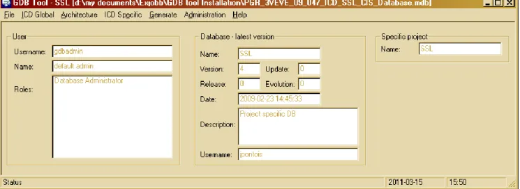
Figure 11. GDB tool ... 20
Figure 12. Table Car ... 24
Figure 13. Table Revision... 25
Figure 14. Data tables for Car with different revisions ... 26
Figure 15. Create modification form in Wire ... 27
Figure 16. Wire change process ... 27
Figure 17. Example of ICD data [1] ... 36
Figure 18. Table Car in all 3 sections ... 38
Figure 19. Graphical user interface... 43
Figure 20. Change menu ... 44
TABLES Table 1. DBMS comparison ... 15
Table 2. Entities for DB administration ... 28
Chapter 1
INTRODUCTION
1.1 Background
Bombardier Transportation is a rail equipment manufacturer with operations in 35 countries and has 33,800 employees. The operations include Rail vehicles, Propulsion and Controls, Bogies, Services, Transportation systems, and Rail control solutions.
Bombardier is divided in several divisions, and the one that design intercity trains in Västerås is Passenger. The Passenger division is divided in several departments.
The department Software, Design and Implementation is responsible for developing Train Information Systems (TIS) which includes Train Control and Management (TCMS), Passenger Information System (PIS), and Closed Circuit TV (CCTV). TCMS have a central role to control and monitor a modern train and have a lot of interfaces to different systems that are distributed in the train, such as doors, pantograph, HVAC (Heating Ventilation and Air Conditioning) among others. Some of these systems are specified and bought from external subcontractors and others are designed by Bombardier. The interfaces to the systems are different kind of serial buses, or the interface is discreet and communications is via digital or analogue inputs and outputs.
For testing the system designs, different kinds of test equipment are used. The interfaces to those test equipment‟s needs to be configured for the systems interfaces which are unique for every project.
In the vehicles, several kinds of buses are used: Multi Vehicle Bus (MVB), Internet Protocol Train bus (IPT), and the serial buses RS 232, RS 422, and RS 485.
A big challenge in ongoing projects is to handle necessary updates of the different interfaces without that error and inconsistencies arise.
1.2 Motivation
The goal is to evaluate and establish a central storage place for all data that is needed in the development process of the TIS systems‟ interfaces; this data is named interface data in this thesis. The interface data is all data regarding bus communication between units and I/O operations from the units in the train.
For communication on a bus, telegrams are used for transferring data between units; the telegrams are either sent on regular basis, process data (PD), or sent on events, message data (MD). All information regarding telegrams shall be stored in the storage place, both the
although many values are set at run-time. An example is when a passenger display in the train communicates to the train computer system that the temperature has exceeded its maximum temperature value at the display, then the variable FtemperatureExd is set to the value fault at run-time; otherwise the value will be ok. The storage place for interface data will contain the variables and when applicable, constraints the values to the possible ones, in this case the values fault and ok.
Bombardier has developed a database (DB) tool to store a part of TIS interface data, named Generic Database Management Software (GDB tool). It was created at Bombardier‟s site in Crespin (France) and is based on Microsoft (MS) Access. GDB tool is both a database and a user interface application for dealing with the data in the database. Every project has its own database contained in an mdb-file (MS Access), the file is stored by the version-control program Visual SourceSafe; this guarantees version version-control and a possibility to roll back to an earlier version of the project. But there is no possibility to check which changes that have been made between two versions. Also, only one user at a time can access a certain project unless a user has copied the mdb-file and there are two or more users working in parallel; this causes inconsistency and shall be avoided.
The software engineers complain of GDB tool‟s usability, that it is difficult to understand in which order the interface data shall be inserted; the tool only has support for some of the buses that are used in a train. It also lacks some functionality such as multiple access to a project, the ability to check which changes has been made, an approval process when a user updates data. Unfortunately, the developer of GDB tool has quit his employment at Bombardier and the knowledge of the tool is limited. So a better solution is demanded to gain a better controlled environment for storage of interface data; and the storage place shall contain all interface data, not just a part of it.
The interface data that is stored in GDB tool is the same data that is stored in Interface Control Documents (ICD); there is one ICD for every subsystem. For example, the subsystem Displays has an ICD which contains information of functionality and communication for the Display system. These documents are written by the software engineers and are intended for subcontractors and for internal use. The interface data are written in predefined tables in the document and transferred to the database, GDB tool, manually. When the database needs to be updated due to project changes, the ICD documents must be changed accordingly. In other words, a change is implemented in both GDB tool and in the ICD documents; the probability for inconsistencies is high and shall be avoided.
The interface data will be used by system engineers for effectively create deliverables and design software. The central storage place needs to keep information so exports of data into ICD documents, discreet I/O lists, train configurations files (XML and header files), test equipment files, and information for electrical drawings.
1.3 Requirements
Bombardier had some requirements for the new storage solution which the old solution (GDB tool) could not fulfill. This thesis has looked into the possibility to expand GDB tool or use another solution to fulfill the requirements and to have a platform for further functionalities if desired in the future.
The storage solution must ensure correctness and consistency of the data at all times. This to avoid things such as, one user is blocking all other users when he/she has checked
It shall be possible to see what changes have been made between two revisions, who has approved it and why the changes have been made. In other words, a proper approval process is required where a user initiates changes, and another user checks them and thereafter approves the changes if applicable; during this process, blocking other users for reading data is not allowed or that data is updated before an approval is implemented. The functionality to roll back to an earlier revision shall be remained in the new storage solution, because unwanted changes or inconsistency may occur in a project.
The graphical user interface (GUI) shall be more easy to use than GDB tool is today, the users need a more intuitive interface which clarify the insertion order of data.
Simultaneous and multiple access of the stored data is required as more than one user works in the same project, and delays are avoided if several users have access to the same data at the same time. To prevent inconsistency, several users can update data in the same project but they are not allowed to update the same data concurrently.
1.4 Problem Formulation
To store and manipulate data, some kind of database is the most common solution; it is possible to store the data on regular files at a server, but much functionality that are provided with a database solution will be lost or difficult to implement. This thesis looks into a database solution for storing the interface data.
The main problems that this thesis focuses on are listed below; the problems are numbered for easy reference in this report.
Kind of Database
There are different kinds of databases, depending on how the data is modeled and linked with each other. We need to establish which kind of database model that is best suited to solve our particular problem; if GDB tool is one of these tools that use the chosen database model, then it will be a candidate for the new database solution.
P1 – What kind of database model shall the storage of interface data be based on? Is GDB tool based on the chosen database model? If so, can it be expanded to fulfill the requirements or shall a complete new solution be realized?
Change Management
The work process of handling interface data lacks proper change management today because there is no approval process when a user does a change, which means that no one is checking if the changes are correct. And there is no possibility to retrieve delta information between two revisions in the database, in other words to check what changes that have been made.
P2 – How shall the design of change management (revision control) be carried out? Are there any good examples that can be realized? How can delta (difference) information be retrieved from the database regarding changes between two revisions?
ICD Data Consistency
In the current solution, the software engineers create project specific ICD documents in MS Word which contains interface data regarding bus information. This information is written before it is inserted manually into GDB tool, which can lead to inconsistency if there is some mistyped information in either source; or if either of ICD document or GDB tool is
P3 – How can inconsistency be avoided between data in the ICD documents and those stored in the database?
User Concurrency
One requirement is that several users can login to the same project concurrently, this because several users‟ works in the same project and need to check or update data at the same time. With this requirement, we need to ensure that inconsistency is prevented if several users try to update the same data.
P4 – How can multiple logins to the same project be realized? And how can users be allowed to read the same interface data concurrently without blocking each other or avoid that inconsistency arise? How can several users update the interface data in the same project without interfering each other? How shall the solution prevent that users tries to revise the same data between two approved revisions in the database?
Database Architecture
A database system must be designed for a deeper understanding of the problem and to ensure that all information are included in the solution and then in the implementation; this to gain a sustainable solution. A good design also makes the solution transparent for others to understand the construction of the database.
P5 - How shall the design of the database system be carried out such that problems P2, P3, and P4 are fulfilled as well as Bombardiers requirements? What kind of data shall the database contain and how shall it be related to each other?
Graphical User Interface
The database solution needs a user interface program to communicate with the database; this because an ordinary user do not have database knowledge. And in order to be intuitive and user friendly, the user interface program will have some kind of graphic interface with a logical order of buttons, drop-down menus, and presented information.
P6 – How will a GUI look like to achieve the users‟ acceptance regarding intuitive handling of interface data? How shall input of interface data be carried out? What kind of documents needs to be exported and how shall it be realized?
Data Security
The interface data is very important in a project as it contains the key information between different systems in a train; this data needs to be protected from distortion and unauthorized manipulations. If the data for some reason have errors, rolling back to an earlier version is a requirement from Bombardier.
P7 – How can unauthorized access to the database and the user interface program be avoided? What kind of user privileges shall the new storage solution have? How shall the design for rolling back the interface data to an old revision be implemented?
1.5 Contributions
This thesis has answered the questions addressed in the problem formulations defined in chapter 1.4. There are problems such that disc failure issues, or proper login handling among others, that this thesis has not answered due to lack of time. The chosen database supports a good solution of these problems and they are mentioned in chapter 7.1 as a recommendation for implementation in the future.
The contributions from this thesis are numbered for easy reference in this report. Database Management tool
C1 – A database management tool has been evaluated and chosen with respect to the problems P1, P2, P4, P5, and P7.
Change management
C2 - Three different kinds of change management solutions were evaluated where a well-proven one was chosen and adapted to suit our database. The change management solution solves the user concurrency problem and handles user privileges; it also gives a foundation for rolling back the database if necessary. This contribution is related to the problems P2, P4 and part of P7.
ICD Data Consistency
C3 – A process for handling ICD data has been proposed where the database is the main source for ICD data. This guarantees that the interface data always are accurate and updated in a controlled environment. This contribution is related to problem P3.
Graphical User Interface
C4 - A graphical user interface program has been created to communicate with the database. This is related to problem P6.
1.6 Limitations
This thesis has considered the whole process with a solution for storage of interface data, but only implements a part of the solution due to lack of time. The implementation covers graphical user interface program and database management, with respect to the IPT bus. The other bus types are considered in the architecture of the database management solution but not implemented. The discreet analogue and digital I/O signals are not considered in the design solution but as they are independent of the bus data, it is quite easy to implement them in the same database solution.
Interface Data Process
The process of the interface data from input to the database, then output to various kinds of documents is shown in
Figure 1. Interface data process. The green boxes represent the database solution in this thesis.
1.7 Methods
This thesis spans from understanding current work process regarding handling of interface data as well as document storage, implement user interface, database management, and testing that the solution works as intended. For this several methods have been used as interviews, reading literature, and using software tools.
Studies of Work Process
Every software tool is linked to a working process and either needs to adapt to the other. In order to understand the current work process regarding handling of interface data, interviews with several employees, both managers and design engineers, have been carried out. The objective was to improve the process as well as the data handling. Internal Bombardier documents and various kinds of interface data files were collected, see documents [1], [3], [4], [5], and [6].
The current database GDB tool was studied in order to understand what kind of data and in which format the new database solution must handle, this study were primarily for assurance that all interface data regarding IPT bus was taken into consideration in the new solution.
The ICD work process was investigated by interviews with Product Data Management (PDM) responsible within Bombardier, mainly Martin Svartz.
Studies of Relevant Change Management Methods
Choosing a method for change management is one of the main problems in this thesis, the information of how to revision control the data in the database is not well documented on internet. The main sources for the solution presented in chapter 4.2 are interviews with Attila Flamborg, experienced with Oracle databases; and Dag Nyström, experienced with Mimer databases.
Testing the Solution
To test the new database solution, a graphical user interface program has been developed to interact with the database and thereby confirm the proposed solution.
Various functions, such as revision control, metadata about projects, and that user data are consistent and correct were tested by running a test project; the test project have several fictive users with different user rights and several modifications were open at the same time for testing that reading and writing to the database works as intended.
Chapter 2
RELATED WORK
This chapter describes related work and related areas; also a description of the previous database tool, GDB tool, which is used within Bombardier, is given.
2.1 Database Theory
Some basic database theory is described for easier understanding of this thesis intended for readers not familiar with databases and their functionality. For further knowledge in this area, see [2] (Swedish), [24] or other literature in this field.
Introduction
A database is a collection of data that describes or models something, in our case the database models the system interfaces for TIS data. A database management system (DBMS) is a program that organize, store, manage, and retrieve data in a database. Examples of DBMS programs are Oracle, MySQL, DB2, Microsoft (MS) SQL Server and Postgre SQL. MS Access is sometimes mentioned in this context but it is rather an application program using JET as DBMS; in this thesis MS Access will be considered as a DBMS with the implicitly that JET is running in the background. A database and DBMS is often mistaken for each other but the database is the collection of data and DBMS is a program handling the data in the database.
Database Models
A database is often quite complex with different kind of data which is related to each other; in order to organize these data, a database model is used. There are several database models which the most common ones are Hierarchical, Network, Relational, and Object-oriented models.
Hierarchical Model
A hierarchical model is a tree-structure model with parent/child relationships between data objects. A parent object can have multiple children but a child can only have one parent [27], see Figure 2.
This model is good for simple one-to-many (1:N) relationships but does not perform very well when dealing with more complex many-to-many (N:M) relationships. Hierarchical databases were popular from late 60‟s through 70‟s, but have become more or less obsolete when the relational model was developed.
Figure 2. Hierarchical model Network Model
The network model was invented by Charles Bachman [28] and was first published 1969. This model uses records and sets to represent data objects (records) and its relations (sets). This model is similar to the hierarchical model but allows a record to have N:M relationships. See web site [29] for further details.
Relational Model
The relational model was invented by Edgar Codd [31] in 1970, when he issued the paper “A Relational Model of Data for Large Shared Data Banks”.
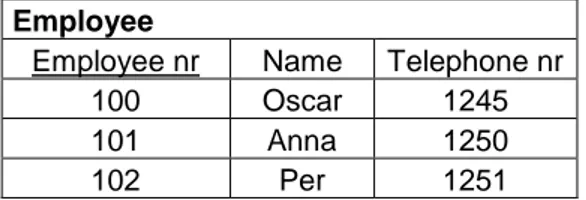
In a relational model, which is the most common model used today, the data are organized in tables. A database contains entities (objects) and its attributes, and relationships between the entities. The columns in the tables are the data attributes, and the rows (also named tuples) contain the actual data. The tables are the entities of the database and the associations between tables are the relationship. Figure 3 shows an example of a database table (entity) named Employee with the attributes Employee nr, Name, and Telephone nr.
Employee
Employee nr Name Telephone nr 100 Oscar 1245
101 Anna 1250
102 Per 1251
Figure 3. Database table Employee
To identify specific rows, keys are used; several attributes can be combined to act as a key. In this example, we can use Employee nr and/or Telephone nr as keys provided that they are unique for each employee. The attribute Name is a bad choice of key because of the possibility that several employees have the same name is quite high. There are several kinds of keys: primary, candidate, foreign, super and alternate keys. Here we only explain the primary key (PK) and foreign keys (FK), for further details about keys, see [2] or [24]. A primary key is a unique key to identify each row in a table and there is only one primary key for each table (could be combined from several attributes). In table Employee, Employee nr is a primary key which is denoted by the underline in the table. A foreign key is a
we have a table Salary that lists how much each employee earns every month, the foreign key will be Employee nr which refers to Employee nr in table Employee. See Figure 4.
Salary
Salary Id Employee nr Salary
1 100 15000
2 101 15500
3 102 17000
Figure 4. Database table Salary
It is possible to skip a value in some attributes (not keys), it will be denoted NULL which means they are empty (not zero).
The DBMS can set up Views of the database so different users/application programs only see a part of the database, this is useful to prevent access to certain parts and this functionality makes it possible to customize the appearance of data.
A database schema is a description of the database structure containing tables, attributes, relationships between tables, and indexes; in other words metadata of the database. For further details, see [26].
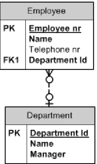
In the conceptual stage of designing a relational database, Entity-Relationship (ER) diagrams is used. ER diagrams are used to draw entities with its attributes and relations to other entities. Figure 5 shows an example of an ER diagram, the relationship shows that one employee belongs to one department but a department can have several employees. Employee has the primary key Employee_nr and the foreign key Department nr, the latter indicates a relation to table Department. Figure 5 is drawn in Crow‟s notation. Employee and Department are called entities and will later in the design process end up as tables.
Figure 5. Simple ER diagram Object-Oriented Model
An oriented model has objects, classes, and inheritance very similar to an object-oriented programming language. Usually the same type system is used both in the DBMS and in the application program for easier programming. Figure 6 shows an example with two
Figure 6. Object oriented model [30] Programming
In order to create, update, and remove tables in a database, the Structured Query Language (SQL) is the most common one to use. It is a standard language for accessing relational and object-oriented databases, all major DBMS‟s support SQL. It is possible to integrate SQL in application code written in, for example, C++ or C#. Unfortunately, the DBMS‟s have their own variants of SQL which differ slightly from each other; this complicates the design and coding. Therefore, Microsoft has developed the language Open DataBase Connectivity (ODBC) for a better standard communication between the application code and the DBMS. See web sites [20] and [21] for further details about ODBC. An example of SQL code is:
SELECT * FROM Employee WHERE Name = “Kalle”;
This query asks for all data that has the name Kalle in the table Employee.
To achieve better control over a database, it can have active rules called triggers; see web sites [22] and [23] for further details. It is procedural code that executes when certain events happens on a tables(s), view(s) or database. These events are insert, delete, and update of a table; triggers can be used for logging data, prevent unauthorized deleting of data, or enforce certain business rules.
Most of the DBMS‟s today support stored procedures, which are code stored on the database server and can be called from an application program, another procedure, or a trigger. The procedure returns row values from a table and can have parameters as input. If we want a single return value, functions can be used.
For describing relations, Database Design Language (DBDL) notation can be used, the format is:
Employee (EmployeeNr, Name, TelephoneNr, DepartmentId) Primary Key EmployeeNr
Foreign Key DepartmentId references Department (DepartmentId) This means that table Employee has the attributes EmployeeNr, Name,
TelephoneNr, and DepartmentId, where DepartmentId is a foreign key related to table Department.
Integrity Constraints
In a database, integrity constraints are needed to avoid errors as much as possible. DBMSs have slightly different integrity rules but most of them apply to the described rules below. Here, we describe five integrity rules as denoted in chapter 7.2 in [24]: required data, domain constraints, entity integrity, referential integrity, and general constraints. The rules are for relational DBs primarily but similar rules can be applied for other kinds of databases.
Required Data
Some data are required in a database; for example if we have an employee, he must have employee number. This requirement is called required data. The SQL ISO (International Organization for Standardization) standard states that the SQL commands CREATE and ALTER TABLE can be specified as NOT NULL, according to chapter 7.2.1 in [24]. This means that we can enforce data to not have NULL values.
Example:
Name VARCHAR (20) NOT NULL
This means that attribute Name is not allowed to be empty, it must have a name. Domain Constraints
Data have a legal set of values, so called domain constraints. For example, may employee number have minimum value 100000 and maximum value 999999, or user name may have the constraints of only allow letters. According to SQL ISO standard, domain constraints can be set in the CREATE and ALTER TABLE statements with the CHECK and CREATE DOMAIN constraints, see chapter 7.2.2 in [24].
Example with CHECK constraint:
Employee_number INT NOT NULL CHECK (Employee_number >= 100000 AND Employee_number <= 999999))
Entity Integrity
A primary key must have a unique and NOT NULL value for each data row (in a table). The PRIMARY KEY constraint can be used with the CREATE and ALTER TABLE statements according to SQL ISO standard. See chapter 7.2.3 in [24] for further details.
Referential Integrity
Referential integrity [8] means that all references in the database must be valid. If table Salary have a reference of name Kalle from table Employee, then Kalle must exist. Foreign keys must always have referential integrity, in other words refer to a valid primary key; if the primary key is deleted, the DBMS shall either delete the foreign key as well or refuse to delete the primary keys. According to SQL ISO standard, referential integrity can be set in the CREATE and ALTER TABLE statements with the FOREIGN KEY constraint, see chapter 7.2.4 in [24].
Example:
FOREIGN KEY (Employee_Id) REFERENCES Employee (Employee _Id)
This means that attribute Employee_Id in table Salary refers to attribute Employee_Id in table Employee.
General Constraints
A general constraint is similar to domain constraints but is applicable to more than one table. The SQL ISO standard has the CREATE ASSERTION statement for allowing general constraints to be used by several tables. See chapter 7.2.5 in [24] for further details. This feature is not available in all DMBSs.
Transactions
According to [24], “A transaction is a logical unit of work consisting of one or more SQL statements that is guaranteed to be atomic with respect to recovery”. This means that a unit of commands (transaction) is indivisible regarding execution of them; other concurrent executing commands are not able to interrupt. A transaction either COMMIT or ROLLBACK, in other words it either completes the execution successfully or aborts the execution and undo eventual changes in the database.
ACID
For reliable database transactions: Atomicity, Consistency, Isolation, and Durability (ACID) properties are recommended.
Atomicity
An indivisible transaction with the property that either shall all commands in the transaction be executed or none.
Consistency
Quote from [24], chapter 22.1.1: “A transaction must transform the database from one consistent state to another consistent state”. This rule can only be implied for constraints that have been specified in the database schema.
Isolation
In concurrent transactions, a transaction must be executed independently of other transactions.
Durability
All committed transactions shall be in the database permanently and must survive a system failure; this is usually done by keeping transaction logs.
Concurrency
When multiple users access a database concurrently, locking is needed to prevent them from writing to the same data and have inconsistency as a result. There are two main concurrency control mechanisms in a database: pessimistic and optimistic. A pessimistic concurrency control locks the records immediately while in optimistic the locking occurs during update of the records. It is recommended to use pessimistic when the risk for conflict is high and optimistic if the system have relative few users and the updates are not likely to occur at the same time.
2.2 Database Management System Survey
In order to choose a Database Management System (DBMS), we must first evaluate if the database shall be relational or object-oriented. An object-oriented database works with objects just like an object-oriented programming language, so the database management and the application program becomes the same environment; a relational database on the other hand have two environments, the application program and the DBMS. An object-oriented DB is good when dealing with objects such as multimedia or other complex data types [32]. A relational DB is more standardized (SQL) and quite easy to understand with its tables and relations. Also, the literature of relational DB‟s is extensive comparing to object-oriented DB‟s. This thesis will use a relational DB solution because it is easy to find literature in this field and because the current DB (GDB tool) is a relational DB and we can benefit from the work that is already done. This is related to problem P1 and contribution C1.
GDB tool is based on MS Access 2003 which is part of the MS Office package that is installed on Bombardier‟s current computer network, an eventual expansion of GDB tool should therefore still be based on MS Access 2003. At Bombardiers site in Västerås this tool has only been used in two projects, so the user experience is quite low and acceptance for a new tool is high.
A new or modified DBMS tool (GDB tool) will be needed to achieve the requirements and expectations in this thesis. We will use standard implementation in order to be as independent as possible of a certain DBMS tool, but every tool has its own way of doing things so the solution will not be totally independent. A DBMS tool shall be able to handle several requirements; in this thesis following requirements shall be considered: 13, MR-14, MR-23, MR-24, and MR-25. See appendix A for further details.
For comparison, following DBMS‟s have been chosen with the criteria of free development software: MS SQL Server 2008 R2, Mimer SQL Enterprise, MySQL 5.1, and MS Access 2003. MS Access 2003 is chosen because GDB tool is based on it, it will then be possible to check if GDB tool could be modified to fulfill the requirements. Table 1 shows a comparison between the DBMS‟s.
Comparison MS Access 2003 MS SQL Server 2008 R2 MySQL 5.1 Mimer SQL Enterprise Row-level locking (MR-13)
Yes [12] Yes [13] Yes (InnoDB engine) [11] Optimistic concurrency control (no locking) Simultaneous and multiple access to the database (MR-13)
Yes[12] Yes [13] Yes Yes [15]
Referential
integrity (MR-14)
Partially [8] Yes [8] Yes [8] [9] Yes [15]
ACID transactions (MR-24)
No [12] Yes [7] Yes [9] Yes [15]
Password
protection/Access privileges (MR-23, MR-25)
Yes [12] Yes [14] Yes[10] Yes [15]
Support database triggers
No [12] Yes [13] Yes [10] Yes [15]
Free software Free software for students
Free software for students
Free software Free software for developers Table 1. DBMS comparison
As MS SQL Server has excellent developer community, fulfills all requirements, and Bombardier‟s network is based on Microsoft‟s products and they have expertise available to continue with this solution it is chosen as the tool to work with in this thesis.
This thesis could have been done with MySQL 5.1 or Mimer SQL Enterprise, with slightly different solutions. MS Access 2003 would require more workarounds and is not suitable for this thesis.
2.3 Train Information System
Train information system, TIS, is investigated due to data terminology and how everything fits together. The same terminology will be used in the new solution as far as possible.
The interface data handles a variety of different kind of signals and in different formats, such as IP signals, MVB signals, Serial link signals, and discreet I/O signals. In this thesis only IP interface data will be considered.
The TIS systems have several devices in the train; the devices belong to a certain device type which has a connection point for communication between devices. The devices are linked with buses and messages are sent with telegrams. A simple train layout is shown in Figure 7.
Figure 7. Simple train layout [3]
A device type is a type of system such as CCTV or HVAC; a complete list of device types is in appendix C in [1]. There can be several devices belonging to a device type.
A telegram consists of a header and dataset. It can be either message data (MD) or process data (PD); MD‟s are event driven messages and can handle dynamic size data, and PD‟s are messages sent cyclically with static data size [5]. A dataset consist of several signals which are either set or not in the messages, all signals belonging to a dataset are always sent in the messages; Figure 8 shows an example of a dataset. These tables with all signals are standardized for each system and a cross in column X indicates that this particular project will use the appointed signals. A dataset may contain other datasets, see chapter 4.2 in [5]. For further details about MD and PD headers and their contents, see chapter 5 in [6].
DISCtrlOp2 X Req
- level
Data name Description Type Value
Interpretation
Byte Offset X B CEndMessage End of message
This byte determines the last block of sub messages. Only used in case of multi-block messages. F10
UINT8 0 = not end of message 1= end of message 0 X B CSubMessage Nb
Sub message number
This defines the block message ordering F11 UINT8 0 = single message 1 to 4 = block message 5-7 = reserved 1 X B CMessageLen gth Number of CHART F12 UINT16 2-3 X B CMessage Message
String message (character and bitmap format)
This message shall be UTF8 encoded F13 CHART 8 [1000] 0..1000 4-1003 Reserved UINT8[ 18] 1004 - 1023 Figure 8. Dataset example [4]
A connection point connects two or more devices to each other with the correspondent dataset and a direction, named source or sink.
A bus connects devices, either directly or via switches, there are several buses on a train and the communication between them is via units named CCUO (Central Computing Unit Operation).
The train have several cars and a complete unit of cars are called consist. According to requirement MR-34, different configurations shall be supported by the database, for example 7 or 8 car-trains which correspond to different consists configurations.
Bus architecture contains of devices, types of buses, applied cars/consists.
In the current solution, the input of data into the database must be in a certain order because of dependencies, see chapter 5 in [3] for further details. Although we will have a different solution and probably another kind of database management, it is likely that the
In GDB tool the inputs are divided in three main areas: ICD Global, Architecture, and ICD Specific. The insertions follow the steps below.
1. ICD Global a. Device Type b. Dataset c. Connection Point 2. Architecture a. Bus b. Device c. Car Type d. Consist Type e. Bus Architecture 3. ICD Specific
a. MVB or IP Attributes (parameters related to communication)
The new solution must be able to export xml and header files of the IP interface data. There is one xml file per system; a truncated example is in appendix B (telegrams and datasets are removed for space reasons). There is one header file per system and one per telegram; an example is in appendix C.
2.4 GDB Tool
Generic Database Management Software (GDB tool) is a relational database with user interface application and is developed by Bombardier at Crespin (France); the developer has quit his employment at Bombardier so a deep understanding of the tool within the company is lost. The objective with the tool is to handle all interface data regarding bus communication. It is based on MS Access 2003 which is part of the MS Office package that is installed at Bombardier‟s computer network.
Data Storage
According to [1], MVB and IPT bus protocols are supported by GDB tool even though only IPT bus based systems have been stored in the database in Västerås. GDB tool is missing support of the serial buses RS 232, RS 422, and RS 485.
GDB tool is not able to export discreet I/O lists, serial interface configurations, and MVB signal lists; the latter at least at Bombardier‟s site in Västerås. Figure 9 shows the current process, from GDT tool point of view, of input and exports from GDB tool in Västerås; it also shows the database Vehicle Control Simulator (VCS) which is used in testing the design. Other Bombardier sites might have a slightly different process.
Figure 9. Current interface data process
The database stores data about system types, devices (instances of systems), buses, cars, consists (train configurations), telegram attributes, datasets (data contained in telegrams), among others. They are stored in tables with attributes and relations between the tables. For example is table CarType which has the attributes CarTypeId, CarTypeName, and MaskIndex; see Figure 10. CarTypeId is a unique identification of the car, CarTypeName is the name of the car, and MaskIndex is a mask to distinguish every car when communicating with it; the same car can occur several times in a train set, so mask index makes them unique.
Figure 10. Table CarType Graphical User Interface
In GDB tool the data inputs are divided in three main areas: ICD Global, Architecture, and ICD Specific. According to [3], the insertions follow the steps below.
4. ICD Global a. Device Type b. Dataset c. Connection Point 5. Architecture a. Bus b. Device c. Car Type d. Consist Type e. Bus Architecture 6. ICD Specific
a. MVB or IP Attributes (parameters related to communication)
The interface data has a lot of dependencies, for example a connection point cannot be inserted without dataset, and a dataset cannot be inserted without a device type.
The terminology is confusing as ICD is a name of a document type rather than database related, even though the same interface data is stored in both ICD documents and in GDB tool. Figure 11 shows the interface menu for GDB tool with ICD Global, Architecture, and ICD Specific as drop-down menus.
In the user manual for the tool [3], there are explanations of how to use it. Unfortunately, the insertion order of interface data is not described in correct order. For example, the manual starts with insertion of connection points even though device types and datasets must be inserted first. This, together with confusing terminology such as ICD Global and ICD Specific, confuses the users of the tool.
Change Management
There is no possibility to check which changes have been made in the tool, so called revision control even though the database files are stored in Visual SourceSafe. This only guarantees version control and possibility of roll back but no possibility to get knowledge of what happened between two versions. Also, there is no possibility to get a delta document (difference) to see which changes has been implemented or comments of the reason for the change.
User Access
Multiple and simultaneous access to the current database is not allowed, only one user at a time can access the database; this is a big problem as the purpose of the database is to let several software engineers handle the same data. This problem will be worse when more interface data are put in the database, either GDB tool will be expanded to handle more bus protocols and other kind of interface data or a new database solution is needed.
Administration
Users will be applied roles in the tool, and each role is associated to privileges. For example, the role Developer gets privileges to do project related changes in the database. GDB tool will only give access to areas in which the user has privileges. See chapter 7.2 in [3] for further details.
It is also possible to set which actions/privileges that each specific role shall have. For example, decide that role Developer can access the actions Delete Data or Backup Database. This is described in chapter 7.1 [3].
Chapter 3
DESIGN INVESTIGATION
To understand the complexity of the problems and how to solve them, some investigation is needed. First of all, we need to know exactly what requirements there are on the new solution in order to do the rest of the investigation properly.
Change management is a key issue for this thesis and several revision control methods are investigated. How to solve the potential inconsistency between ICD documents and the database is also investigated.
3.1 Requirements
In agreement with Bombardier, the requirements in appendix A shall be fulfilled; this lists the main requirements (MR) for the database to be an acceptable solution. In this thesis only requirements with priority 1 must be implemented. Requirements with lower priorities shall be considered in the design if applicable, but not necessarily implemented in this stage. The priority 1 requirements are ICD data consistency, revision control, simultaneous and multiple access, and database management integrity constraints.
3.2 ICD Data Consistency
ICD documents have templates for each system, even though they have not been used in Bombardier Västerås. These templates are supposed to be used in conjunction with GDB tool, so interface data is mapped onto these templates. These templates are not stored in Bombardier‟s PDM system, neither are most of the ICD documents.
Word documents is usually created from a template stored in PDM to ensure that metadata such as document number, revision, approver, type of document, among others are synchronized with PDM.
Bombardier uses a PDM tool named Metaphase to store documentation, especially project related documentation. This is mandatory according to [33]; a Swedish BT directive for documentation, technical documents shall be stored in BT‟s common PDM system. This because technical documents shall be available for 40 years with respect to requirements of traceability, spare parts, and recycling.
There are mainly two options of how to deal with consistency between the ICD‟s and the stored interface data in the database. Option one is to store the word file in the database as it
The other option is to store only the interface data and export it to an ICD file for the current subsystem. The ICD‟s are stored in the PDM system. When changes occur, the ICD is checked out from PDM and the changed interface data is exported to the ICD word file, and then checked backed to PDM via an approval process. In this case, the ICD‟s are stored properly according to Bombardier PDM policy and the database does only handle the interface data.
The conclusion is to use the second option in our solution as it is in line with Bombardier policy of documentation, and simplifies the database solution as binding data in the word documents to tables in the database is difficult. This solves the issue described in problem P3 and is contribution C3.
3.3 Change Management
Change management is needed to maintain good quality of the interface data as a change process have responsible persons that approve the changes, and hopefully the data are checked for errors before an approval is implemented; this to fulfill requirement MR-12. It also guarantees that authorized and project related users are doing the changes and approvals, as every user will have different privileges in the projects, according to requirement MR-23, see appendix A, and problem P7.
Problem P4 raises the issue when several users want to update the interface data in the same project, this shall be done without the updates interfere with each other and that no inconsistency occurs. This in conjunction with requirement MR-13 which states that users shall have simultaneous access to the same project but not be able to change the same data, the requirement also states that users shall be able to check approved data at all times. This requires some kind of locking in the database, and is investigated in this chapter.
In order to be able to export delta document (requirement MR-12) and roll back (requirement MR-22) to an old revision, all changes need to be saved in the database. This chapter will investigate how this can be implemented, see problems P2 and P7.
An issue is how to realize all demands which we have on the change management, in this chapter we will investigate if there is a design which fits our needs or if it is best to implement a new design solution; this according to problem P2.
In order to fulfill the requirements MR-12, MR-13, MR-22, MR-23 and solve the problems P2, P4, and P7; three different kinds of solutions have been investigated. The first we call the finance model, because it is used in the finance system for keeping track of changes. The other solution is a simple copy tables when a change occur, this will be called copy model. The third solution is used in a database that handles cabling information within Bombardier, this will be called Wire model (from the DB Wire).
Locking
The requirement with simultaneous and multiple users (MR-13) demands that the system can have several open modifications; the same interface data cannot be modified though, so the system need to lock those interface data for writing. There are two main concurrency control mechanisms in a database: pessimistic and optimistic [34]. A pessimistic concurrency control locks the records immediately while in optimistic the locking occurs during update of the records. It is recommended to use pessimistic when the risk for conflict are high and optimistic if the system have relative few users and the updates are not
with another modification is quite high; therefore pessimistic concurrency control is to prefer.
User Privileges
In order to know which user that has logged in to the database through the application program, the latter must ensure user identification. As the computers at Bombardier are in a MS environment with proper user identification, those user identifications will be used as well in the application program and database, and synchronized with Bombardiers system.
In a project, a user shall be able to read data in every project (requirement MR-13); and the change management process requires that a user shall be able to modify and approve data. This gives us three different user privileges: read, modify, and approve. These privileges must be granted by authorized users and non-project related data must be handled as well.
Therefore, the users have different roles that are not linked to a specific project as the privileges are. In the database, every user will have a role linked to him to ensure that the user is authorized to manipulate data, see requirement MR-23. For the change management purposes, the roles DB Admin, Admin, Viewer, and Engineer are satisfactory. All user roles will have the reading privilege. Viewers can only get read privileges in a project; Engineers may modify and approval privileges in a project; Admins can change user privileges in a project including his own; and DB Admins can change non-project related data including set roles to users.
Finance Model
This change management model is based on the financial databases that handle currency transactions; they must be able to keep track of all changes in order to restore errors or inconsistencies as well as both internal and external fraud. It is very important for these databases to never remove any data; flags are used to set status of data. In many cases, audit is enabled to keep track of users‟ activities in the database.
It is difficult to find information of this kind of database systems, probably because the finance community and the database system manufactures want their system to be a secret. The basic idea is to keep all data records and use status flags for revision control.
An example is a table Car, which has the extra attributes Revision, Terminated, Superseded, and Lock for revision control; see Figure 12. As no records (rows) are allowed to be removed, a new record is inserted for every change. This means that the index number is not unique so a combined primary key is needed, in this case Index and Revision acts as a primary key. When a change is to occur, a modification is opened and applicable records are set to current modification number in the Lock attribute. Then copy the record to a new row and do the changes. The attribute Terminated tells if a record has been obsolete, and Superseded tells if a record has been updated or not.
This model becomes complex when we need algorithms for rolling back and produce delta documents of the changes. This because we need to keep track of which records that have been deleted (terminated) and in which revision, as well as keep track of latest revision for each car (in this example).
Copy Model
This model is not established on the database system market to my knowledge; it is investigated to establish if a very simple copy model is applicable in our case.
The idea is to copy table(s) when a change occur in a project and thereby have data tables for every revision in the database; the revision is in the table name to differentiate them from each other.
When a user has created a modification and begins to do the changes, the system copies the applicable data table(s) and names them datatablename_ModNr, for example Car_Mod01. There is a table to keep track of the latest revisions and modifications on each type of data table, for example a data table Car with three revisions will be named Car_R0, Car_R1, and Car_R2, see Figure 14; and table Revision contains the modification, both approved and open modifications; it also contains revision number and name of the data tables, see Figure 13. All changes for modification M2, in our example, takes place in table Car_M2.
When the changes are done, an approver (user with approval privileges) approves the changes in the application program. Then the system checks the next free revision number and stores the revised table(s) as latest revision; table Car_M2 becomes table Car_R3 in our example. The problem with this is that another user might have open a modification which affects the same data table(s) and approve his modifications first, a check that the explicit data rows have not been altered must be done before the modification can be approved; if a data row has been altered, the system shall roll back all changes which is easy in this case as we only need to delete the modified table (Car_M2 in the example).
The problem with duplicates of tables for each revision is that the database will grow exponentially fast, especially for many small changes. This model is also against the normal database designs as usually all tables are created before data is put into them; the database structure is decided with all tables and then an application program(s) read or manipulate data in the tables. As the database should be locked for user manipulations, including application programs, as much as possible to prevent errors and ensure correctness of the data; creating new tables after the database is created is not recommended.
A simple example with one data table (Car) which is split into three tables due to new revisions and one Revision table for keeping track of all changes is shown in the Figure 13 and Figure 14.
Figure 14. Data tables for Car with different revisions Wire Model
The wire model is based on the database system Wire which handles cabling information and is used by Bombardier in Västerås. Wire stores information about cabling material and connection points; it has a well-established solution of revision control and is able to export delta documents between two revisions. Wire is an Oracle database.
The database handles harnesses which are point-to-point cabling information, a project have several harnesses; each harness also has material so a manufacturer can build the harnesses from information stored in Wire.
Users have different privileges depending on the projects; a few users have DB administrator rights to change privileges for other users including themselves. The project privileges are approver, engineer, and viewer. Approver can approve changes in a project; an engineer can make changes; and a viewer can see approved data.
When a user wants to do a change, a modification is created, see Figure 15. A modification number is created by writing it manually in the text field next to “Modifiering”. Revision index and date are created by Wire automatically. The user fills in the text fields “Orsak” (means reason) and “Konsekvens” (means consequence); and then clicks on button “Stäng” (means closing) for saving the modification.
Figure 15. Create modification form in Wire
The data tables are divided into three sections: approved, modified, and revised; with the same type of tables and same relations between them. The difference is some flag attributes for revision control. See Figure 16 for the change process with numbering for reference in the text. When a modification has been created, the whole harness structure of the project is copied from the approved section into the modified section with the applicable modification number (1).
When a modification is open it is possible to create, delete or update a data record. All changes are made in the modified section with a flag set which informs of the type of change (new, delete, or update). After approval of the modification, the old data are copied from the approved section into the revised section with revision number and flags from the modified section (2). Then the changed data, except the deleted ones, are copied from the modified section into the approved section (3).
Figure 16. Wire change process Conclusion
The Wire model is chosen to our change management model, this because it is a simple solution which fulfills our needs.
The copy model is too memory consuming and would be inefficient in ensuring correctness of the data.
The finance model is interesting and could probably work in our case but the algorithms for rolling back the database and produce delta information would be too complex.
Chapter 4
SYSTEM DESIGN
The database solution design is described in this chapter regarding database architecture, change management, and ICD data consistency. A simple test plan for testing the design is also described.
4.1 Database Architecture
There are three design steps when designing a database system: the conceptual, logical, and physical designs. See chapter 16 in [24] for details of the methodology to perform these design steps. In this thesis only conceptual and logical designs are applied.
Conceptual Design
For better overview, the entities in the database are divided into two parts: DB administration and DB data.
DB administration handles project metadata, user privileges, and revision control. The entities are User, Role, Project, Privileges, Modification, and Revision; these are described in Table 2.
Entity name Description Occurrence
User Employees with user rights to the database.
Each user have a user role to each project, all users have read privileges on every project.
Role User role: Admin, Viewer, or Engineer.
Each User has one Role.
Project Development of a train set. A project has one modification list and one revision list, can have one or several users.
Privileges User privileges specified per project
Connects one user to one project.
Modification A purposed change that is not approved.
One modification is linked to one project.

![Figure 6. Object oriented model [30]](https://thumb-eu.123doks.com/thumbv2/5dokorg/4816565.129677/19.892.301.604.97.305/figure-object-oriented-model.webp)
![Figure 7. Simple train layout [3]](https://thumb-eu.123doks.com/thumbv2/5dokorg/4816565.129677/24.892.139.788.409.638/figure-simple-train-layout.webp)
![Figure 8. Dataset example [4]](https://thumb-eu.123doks.com/thumbv2/5dokorg/4816565.129677/25.892.97.855.115.782/figure-dataset-example.webp)