Report number: 2019:09 ISSN: 2000-0456 Available at www.stralsakerhetsmyndigheten.se
General data in accordance with the
requirements in Article 37 of the
Euratom Treaty
Decommissioning of the nuclear reactor
Ågesta in Sweden.
SSM 2019:09 Abstract
The purpose of this report is to provide the European Commission with general data relating to plans for the decommissioning of the pressur-ised heavy water reactor Ågesta, situated outside Stockholm, Sweden., which will enable the Commission to determine whether the implemen-tation of the plans is liable to result in the radioactive contamination of the water, soil or airspace of another European Union Member state. The structure of the document follows the recommendations given in 2010/635/Euratom on the application of Article 37 of the Euratom Treaty.
The Ågesta reactor was Sweden´s first commercial reactor. The reac-tor is a pressurized heavy water-moderated reacreac-tor and is located in a rock cavern. The reactor was in operation between 1964 and 1974, and in addition to generating electricity, heat was produced and delivered. The reactor output, after some modification of the core in 1970, was 80 MWth and 12 MWe.
Since 1974, the Ågesta reactor has been in care and maintenance phase. Fuel and heavy water were removed from the site in the 1970s.
This report presents an assessment of the maximum expected emissions of radioactivity to air and water during decommissioning.
The assessment also includes a dose evaluation to a reference popula-tion living close to the power plant.
The dose to the reference group from radioactivity released during normal conditions at the plant is less than 0,001 µSv/year. As the dose to the reference group is less than 10 µSv/year, and there are no excep-tional exposure pathways, no dose assessment is required for other EU member states.
The dose to the reference group from radioactivity released during a hypothetical radiological accident at the plant is less than 1 mSv. As the dose to the reference group is less than 1 mSv, and there are no exceptional exposure pathways, no dose assessment is required for other EU member states.
2019:09
Date: May 2019
Report number: 2019:09 ISSN: 2000-0456 Available at www.stralsakerhetsmyndigheten.se
General data in accordance with the
requirements in Article 37 of the
Euratom Treaty
Decommissioning of the nuclear reactor
Ågesta in Sweden.
SSM 2019:09
This report has been completed by the Swedish Radiation Safety Authority, SSM, mainly based on information provided by the license holder, Vattenfall AB. SSM has controlled that the general data provides the necessary information and that it follows the guideline of the most recent recommendations of the application of Article 37 of the Eur-atom Treaty.
Content
0. Introduction ... 3
0.1. Ågesta Nuclear Power Plant ... 3
0.2. Decommissioning licensing ... 4 0.2.1. Nuclear Licence ... 4 0.2.2. Environmental licence ... 5 0.3. Decommissioning funding ... 5 0.4. Decommissioning plan ... 5 0.4.1. Decommissioning of Ågesta ... 6
1. The site and its surroundings ... 8
1.1. Geographical, topographical and geological features of the site and region .... 8
1.2. Hydrology ... 10
1.3. Meteorology ... 10
1.3.1. Wind ... 11
1.3.2. Precipitation ... 13
1.3.3. Extreme weather... 13
1.4. Natural resources and foodstuff ... 13
2. The installation ... 15
2.1. Brief description and history of the installation to be dismantled ... 15
2.1.1. Brief description of Ågesta ... 16
2.2. Ventilation systems and the treatment of gaseous and airborne wastes ... 19
2.3. Liquid waste treatment ... 22
2.4. Solid waste treatment ... 22
2.5. Containment ... 23
3. Release of airborne radioactive effluents in normal conditions ... 24
3.1. Authorisation procedure in force ... 24
3.1.1. Legislation on nuclear activities ... 24
3.1.2. Discharge limits and associated requirements for decommissioning ... 25
3.2. Technical aspects ... 25
3.2.1. Origins of the radioactive effluents, their composition and physico-chemical forms ... 25
3.3. Monitoring of discharges ... 27
3.4. Evaluation of transfer to man ... 27
3.4.1. Models, including where appropriate generic models, and parameter values used to calculate the consequences of the releases in the vicinity of the plant ... 27
3.4.2. Evaluation of the concentration and exposure levels associated with the envisaged discharge limits for the dismantling operations cited in 3.1 above: . 29 4. Release of liquid radioactive effluents in normal conditions ... 31
4.1. Authorisation procedure in force ... 31
4.2. Technical aspects ... 31
4.3. Monitoring of discharges ... 31
4.4. Evaluation of transfer to man ... 31
5. Disposal of solid radioactive waste from the installation ... 32
5.1. Solid radioactive waste ... 32
5.1.1. Categories of solid radioactive waste and estimated amounts ... 32
5.1.2. Processing, packaging and disposal ... 35
5.2. Radiological risks to the environment ... 36
5.3. Off-site arrangements for the transfer of waste ... 37
2
5.4.1. National strategy, criteria and procedures for the release of
contaminated and activated materials ... 38
5.4.2. Clearance levels established by competent authorities for disposal, recycling and reuse ... 38
5.4.3. Envisaged types and amounts of released materials ... 39
6. Unplanned releases of radioactive effluents ... 40
6.1. Review of accidents of internal and external origin which could result in unplanned releases of radioactive substances ... 40
6.2. Reference accident(s) taken into consideration by the competent national authorities for evaluating possible radiological consequences in the case of unplanned releases ... 40
6.3. Evaluation of the radiological consequences of the reference accident(s)... 40
6.3.1. Accidents entailing releases to atmosphere ... 40
6.3.2. Accidents entailing releases into an aquatic environment ... 44
7. Emergency plans, agreements with other member state ... 45
8. Environmental monitoring ... 46
8.1. General Description ... 46
8.2. Monitoring at Ågesta ... 46
Definitions and abbreviations ... 48
Reference list ... 50
Appendix 1 – The Swedish system for the disposal of spent nuclear fuel and radioactive waste ... 52
Appendix 2 - Clearance levels ... 54
Appendix 3 Detailed flow diagram of ventilation system during dismantling and segmentation ... 65
Appendix 4 Analysis of usage of dose factors from the Predo model for the Studsvik site for estimation of doses to the public from Ågesta ... 66
3
0. Introduction
This document describes the plans for decommissioning of the pressurised heavy water reactor Ågesta, situated in Huddinge outside Stockholm, Sweden. The purpose of this document is to serve as information for the European Commission, and to fulfil the re-quirements of Article 37 of the Euratom Treaty, according to which:
Each Member State shall provide the Commission with such general data relating to any plan for disposal of radioactive waste in whatever form as will make it possible to deter-mine whether the implementation of such plan is liable to result in the radioactive con-tamination of water, soil or airspace of another Member State.
The Commission has recommended that “disposal of radioactive waste” should cover any planned disposal or accidental release of radioactive substances associated with, among other activities, the dismantling of nuclear reactors [1].
The structure of this report follows the guideline in annex 3 of the recommendation of the application of Article 37 of the Euratom Treaty (210/635/Euratom) [1].
The report has been completed by the Swedish Radiation Safety Authority (SSM) mainly based on information provided by the licence holder, Vattenfall AB. SSM has controlled that the general data provides the necessary information and that it follows the guideline of the mentioned recommendation.
0.1. Ågesta Nuclear Power Plant
The Ågesta reactor, Ågesta NPP, was Sweden´s first commercial reactor and was part of the Swedish reactor development program in the 1960s. The reactor is a pressurized heavy water-moderated reactor and is located in a rock cavern situated in the municipality of Huddinge, close to Stockholm, the capital of Sweden. The reactor was in operation be-tween 1964 and 1974, and in addition to generating electricity, heat was produced and de-livered to the district heating system for the nearby city of Farsta. The reactor output, af-ter some modification of the core in 1970, was 80 MWth and 12 MWe.
Since 1974, the Ågesta reactor has been in care and maintenance phase, continuing to op-erate the functions required by the regulations applicable to a nuclear facility in this oper-ation mode.
The rock cavern is owned by the City of Stockholm and will be returned to the owner af-ter decommissioning of the plant. The areas outside the rock cavern are also owned by the City of Stockholm and are used by the Greater Stockholm Fire Brigade (hereinafter called the Fire Brigade) for training and education.
The reactor itself is owned by Vattenfall AB and SVAFO1 with 50% shares each.
Vatten-fall AB is the holder of the nuclear licence.
1AB SVAFO is a non-profit company whose task is to decommission nuclear facilities from previous research and development
activities in Studsvik and to implement intermediate storage of waste from the decommissioning and waste from the research period until final disposal can be carried out.
4
Fuel and heavy water were removed from the site in the 1970s.Two steam generators were dismantled and processed as waste at Studsvik in the early 1990s, before Sweden had obligations under the Euratom Treaty.
0.2. Decommissioning licensing
This section gives a brief overview of the licences that will be needed in order to transi-tion between the different phases of the decommissioning project. The operator must ap-ply for a licence from the Land and Environment Court in accordance with the Swedish Environmental Code and an updated Safety Analysis Report for decommissioning (SAR) needs to be approved by the Swedish Radiation Safety Authority (SSM) prior the begin-ning of the decommissiobegin-ning activities.
0.2.1. Nuclear Licence
SSM reports to the Ministry of the Environment and Energy. SSM regulates the areas of nuclear safety, radiation protection and nuclear non-proliferation within Sweden, and on behalf of the Swedish Government.
The authority works to protect people and the environment from the undesirable effects of radiation. The Act on Nuclear Activities 1984:3 and the Radiation Protection Ordinance 2008:452 with instructions for the Swedish Radiation Safety Authority have been trans-lated into English and can be found on the SSM website (www.ssm.se). The Radiation Protection Act 2018:396 is not yet published in English. These acts and ordinances, to-gether with the Ordinance on Nuclear Activities 1984:14 and the Radiation Protection Or-dinance 2018:506, stipulate the boundaries for all nuclear activities in Sweden. SSM has developed regulations (SSMFS) to give a more detailed framework for Nuclear Power. Some of the regulations are available in English.
In order to start decommissioning and dismantling, a safety analysis report (SAR) must be approved by SSM. The requirement to have an approved SAR is found in SSMFS 2008:1, The Swedish Radiation Safety Authority’s Regulations and General Advice con-cerning Safety in Nuclear Facilities, which is part of the Swedish Radiation Safety Au-thority regulations. The regulations in SSMFS 2008:1 apply to measures required to maintain safety in connection with the construction, possession and operation of nuclear facilities with the aim of, as far as reasonably achievable, taking into account the best available technology, preventing radiological accidents and preventing the unlawful han-dling of nuclear material and nuclear waste. The regulations comprise provisions on tech-nical, organisational and administrative measures. Chapter 9 in SSMFS 2008:1 stipulates the requirements for decommissioning and dismantling. SSM has also issued specific de-commissioning licence conditions in SSM 2016-5866.
The decommissioning process is described in a decommissioning plan.
After approval of the Safety Analysis Report (SAR), each dismantling and/demolition package/project or parts (components, systems or building) of the plant that contains con-taminated or activated systems must be notified to SSM. The size of each package/project is up to the site licensee to decide. SSM conducts regular oversight activities, using a graded approach principle, during the decommissioning and dismantling process. The site will only be released from the regulatory control from the Act on Nuclear Activities by
5
Governmental decision, upon the recommendation of SSM once the final state report is approved.
At the time of writing this report all these licence application documents are under devel-opment.
SSM will not allow dismantling and demolition activities to occur until the European Commission provides an opinion on the Article 37 report for the decommissioning pro-ject.
The purpose of this is for other member states to be able to voice an opinion on the possi-ble effects the decommissioning may have on their soil or airspace.
This document and any required references are part of the submission.
0.2.2. Environmental licence
Decommissioning of a nuclear reactor facility requires a licence according to the Envi-ronmental Code (1998:808). The Swedish EnviEnvi-ronmental Protection Agency, Swedish EPA, the County Administrative Board (CAB), the local Environmental and Public Health Committee and the Swedish Radiation Safety Authority (SSM) are consulted in the licensing procedure and are given the opportunity to propose specific licensing condi-tions.
A licence for the current operation phase was granted in 2008 and is valid until 2020. An application for decommissioning was submitted to the Land and Environment Court in October 2018.
0.3. Decommissioning funding
According to Swedish law it is the owners of the NPPs that have to pay for all the costs of dealing with spent nuclear fuel and its final disposal. They also have to pay the costs of decommissioning of NPPs or other nuclear installations. Since the mid- 1970s the nuclear power operators have been setting aside funds to cover these costs. These funds are ad-ministered by the Nuclear Waste Fund. The Swedish Nuclear Fuel and Waste Manage-ment Company, SKB, conducts regular calculations of the future costs for dealing with nuclear waste and submits the updated budget to every three years. After the calculations have been reviewed, the Swedish National Debt Office then proposes the surcharge for the next few years to the Government, which decides on the amount to be charged. The funds are then distributed to the decommissioning projects as they progress.
0.4. Decommissioning plan
This section gives an overview of the decommissioning plan. It should be noted that this plan is under development and subject to change as it is improved.
Reasons for changes are e.g. results from further radiological surveying that is performed (and will be performed after shutdown) and ongoing and future discussions with disman-tling contractors.
6
0.4.1. Decommissioning of Ågesta
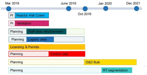
Decommissioning of the reactor is planned as soon as all necessary approvals and permits are granted. The plan is to dismantle the radioactive portions of the plant over approxi-mately 3-6 years. Figure 0-1 shows an overview of the decommissioning planning. Radi-oactive waste will be moved offsite to the Studsvik-site for treatment, conditioning and/or intermediate storage to await completion of construction of the final repositories.
Figure 0-1. Overview of decommissioning planning
The decommissioning strategy is to start with segmentation of the reactor pressure vessel and internal components and dismantling in other part of the facility at the same time. The expansion tanks will be removed at an early stage in order to create space for waste handling as the area inside the rock cavern is limited.
Before commencing the dismantling in the plant it is necessary to carry out several activi-ties to prepare the plant for the decommissioning, e.g. installation of a new ventilation system, modernization of the overhead crane, preparation of an area for buffer storage for transport containers outside the rock cavern, preparation of an area outside the rock cav-ern for clearance measurements of material on site and disposal of waste remaining from the power operation phase of the reactor, like control rods.
The decommissioning is going to be divided into two dismantling and segmentation pro-jects. One project includes segmentation of the reactor pressure vessel and internal com-ponents. Other project includes dismantling and segmentation of other large components, parts of the biological shield, removal of residual piping systems, mechanical and electri-cal installations (including original ventilation systems, cables, cable trays, etc.). The re-sulting overall dismantling sequence will be developed in further detail during decommis-sioning planning. All dismantling activity will be carried out inside the cavern. No chemi-cal decontamination is planned, mainly due to that there is no water treatment facility for contaminated water at Ågesta.
Radiological clearance of the remaining structures may take about 1-2 years after the dis-mantling and demolition are finished. After clearance, the cavern will be sealed with con-crete plugs in both ports to prevent access, see figure 2-2. Ventilation shafts will also be
7
sealed as well as all sewers. The rock cavern is owned by the City of Stockholm and shall be returned when the cavern is sealed. The facility will not be used for other purposes. The waste handling is described in section 5 in this report. In order to optimize the pro-cess several options are available. In Sweden there are two possible disposition routes for radioactive waste: clearance (also referred to as “free release”), either general or condi-tional, or disposal as solid radioactive waste. Disposal of solid waste can be in a surface repository approved for very low level active waste (not an option in the decommission-ing of Ågesta). Sweden has a central final, geological, repository that is licensed for short-lived low and intermediate level radioactive waste (SFR). In the future there will also be a central final, geological repository licensed for long-lived low and intermediate level radioactive waste (SFL) and a final geological repository for spent fuel. See appen-dix 1 for more details.
8
1. The site and its surroundings
1.1. Geographical, topographical and geological features of the
site and region
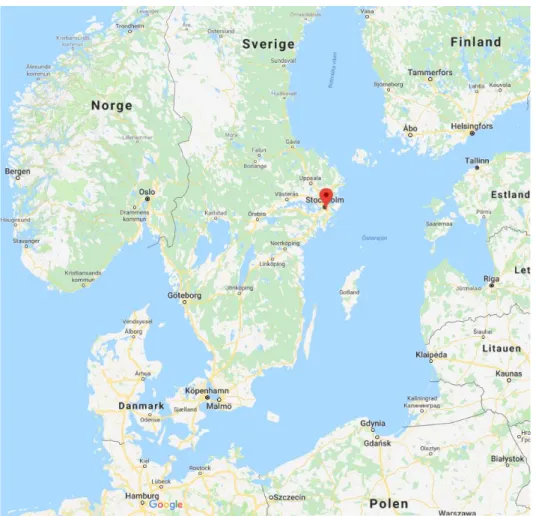
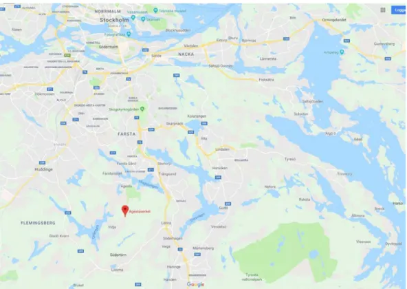
The Ågesta reactor is situated in the municipality of Huddinge near the small city Farsta, close to Stockholm – the capital of Sweden, see figures 1-1 and 1-2. The site coordinates are 59°12'N 18°4'E according to WGS84 (the World Geodetic System 1984).
Figure 1-1. The location of the Ågesta reactor (Source GeoBasis-DE/BKG, Google maps)
Distances to the closest national borders are shown in table 1-1. The nearest population centre in another Member State is Mariehamn, situated on the island of Åland, Finland, about 130 km northeast of Ågesta.
9
Table 1-1. Distance to neighbouring states (Source GeoBasis-DE/BKG, Google maps)
Country Distance to
border (km) Metropolitan area Population (millions) Distance to metropolitan
area (km)
Denmark 470 Copenhagen 2.0 510
Latvia 310 Riga 0.7 440
Estonia 240 Tallinn 0.6 380
Germany 580 Berlin 4.4 800
Finland (Åland) 220 (130) Helsinki 1.1 400
Lithuania 420 Vilnius 0.6 680
Poland 500 Warsaw 3.2 830
The Ågesta reactor is located in a rock cavern (see figure 1-3). The soil layer in the area is thin and therefore exposed rock is widespread on the surface. Clay/silt is the most com-mon type of soil. The area is seismically stable and there is no risk of damage to the facil-ity due to earthquakes. The adjacent surroundings include nature reserves as well as Natura 2000 areas. The area is popular in terms of outdoor recreation.
The surroundings are sparsely populated. A small residential area lies immediately south-west of the site, Vidja (see figure 1-2), as well as a golf club and a riding club. The Fire Brigade operates a practice facility on site. There are no other facilities with correspond-ing emissions in the region and the nearest nuclear facility is the Studsvik site, 70 km south of Ågesta.
10
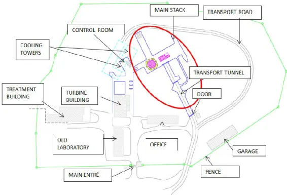
Figure 1-3. An overview of the site. Red circle illustrates the area that is target for the de-commissioning
1.2. Hydrology
The Ågesta NPP is located approximately 11 km from the Baltic Sea which is the nearest coast. The plant was cooled via delivery to the district heating network during normal op-eration or cooling tower when the district heating was bypassed, there was therefore no need for a cooling water intake. There are two smaller lakes in Ågesta NPP’s immediate surroundings, Lake Orlången and Lake Magelungen. During reactor operation water from the waste treatment facility was released to Magelungen. The waste treatment facility no longer exists and the pipe to Magelungen has been cut. Magelungen has no connection to the Baltic Sea. Water drainage from the inside of the cavern but the outside of the pres-sure-retaining steel lining is collected in a drainage pit before it flows via a ditch to Lake Orlången. Measurements of the drainage water verify the absence of radionuclides in the drainage water. Orlången has no connection to the Baltic Sea. Therefore, it is reasonable to assume that there is no body of water providing a potential contamination pathway to another Member State. It should also be noted that the ground water in the area is not a pathway of exposure to other countries either. The hydrology is therefore not described any further in this report.
1.3. Meteorology
Meteorological data for the site is based on data from two nearby meteorological stations, Riksten and Tullinge. These stations are situated approximated 10 km from Ågesta. Like Ågesta, they are not situated by the coast, see figure 1-4. The Tullinge station monitored the weather from 1951-1985 and the Riksten station started recording measurements in 1996.
11
Figure 1-4. Location of meteorological stations, Riksten and Tullinge
1.3.1. Wind
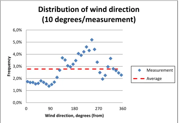
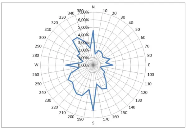
Wind directions and speed from 160000 measurements have been analysed. The most common wind direction is from the southwest, see figures 1-5, 1-6 and 1-7.
Figure 1-5. Frequency of different wind directions. 0,0% 1,0% 2,0% 3,0% 4,0% 5,0% 6,0% 0 90 180 270 360 Fr e q u e n cy
Wind direction, degrees (from)
Distribution of wind direction
(10 degrees/measurement)
Measurement Average
12
Figure 1-6. Wind speed distribution at different wind directions.
13
Pasquill atmospheric stability class is a measurement of turbulence in air and is a parame-ter used in calculations of radioactivity in air. Values range from A (very unstable) to F (stable) and how turbulent the air is affects the spread of activity. Most frequent for the Ågesta location is class D.
There are no specific calculations available for the probability of local temperature inver-sion. Calm conditions, 1-2% of the time and small height differences do not typically yield inversions.
1.3.2. Precipitation
The heaviest rainfall occurs during the summer and usually over a short period of time when thunder clouds appears. Annual precipitation in the area is about 600 mm. Trans-ports or planned operation during the decommissioning are not particularly sensitive to the weather conditions as planned operation occurs in the cavern. There are two drainage pits and pumps that ensure that drainage water inside the rock cavern, but outside the pressure-retaining steel, is pumped away from the plant.
1.3.3. Extreme weather
Extreme weather (storm, tornados, ice storm, heavy rainfall) is rare in Sweden, especially on the Swedish east coast, in relation to other parts of the world. Transports or planned operation during the decommissioning are not particularly sensitive to the weather condi-tions as planned operation occurs in the cavern.
1.4. Natural resources and foodstuff
The County of Stockholm have two water treatment plants, Norsborg and Lovö which distribute drinking water to 1.4 million people in Stockholm. The water is retrieved from Lake Mälaren, Rödstensfjärden. Rödstensfjärden is located 17 kilometres northwest of Ågesta and is the nearest protected area for drinking water.
Groundwater or surface water has no impact on water used in any neighbouring states, see section 1.3.
There are not many agricultural activities around Ågesta. Primary uses of the land are rec-reation, protected areas and populated areas.
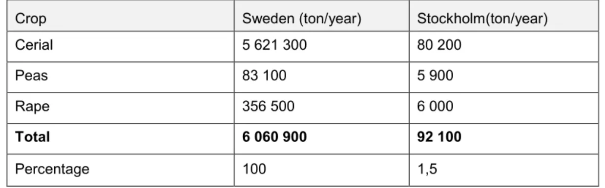
The types of crops produced in 2015 and the numbers of different livestock in 2016 are shown in tables 1-2 and 1-3. The data is taken from the database DAWAS, compiled by the Swedish Board of Agriculture. No specific information exists of export of crops or livestock from this region to other member states. Since the region around Ågesta does not produce any large quantity of foodstuffs, it is fair to assume that the significance of large exports is negligible.
14
Table 1-2. Crops produced in Sweden as a total and in the County of Stockholm. The data is taken from the database DAWAS, compiled by the Swedish Board of Agriculture, for the year 2015.
Crop Sweden (ton/year) Stockholm(ton/year)
Cerial 5 621 300 80 200
Peas 83 100 5 900
Rape 356 500 6 000
Total 6 060 900 92 100
Percentage 100 1,5
Table 1-3. The quantities of different types of livestock in Sweden, produced in Sweden as a total, in the county of Stockholm and in the municipal of Huddinge. The data is taken from the database DAWAS, compiled by the Swedish Board of Agriculture, for the year 2016.
Livestock Sweden no. Stockholm no. Huddinge no.
Cattle 57 874 19 166 112
Sheep 1 489 624 17 057 286
Total 1 547 498 36 223 398
15
2. The installation
This chapter provides a brief description of the facilities to be dismantled and their waste management systems. As waste treatment activities will be minimal at Ågesta most waste treatment will take place at off-site facilities. Only general descriptions of off-site waste management are provided as they are beyond the scope of this report. The descriptions are kept at the level of an overview with the purpose of providing an understanding of the factors relevant to evaluation of the risk to other EU-member states. Details that do not serve this purpose have been omitted from this report.
2.1. Brief description and history of the installation to be
dismantled
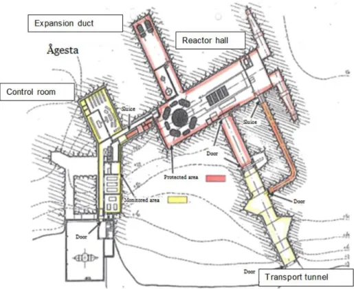
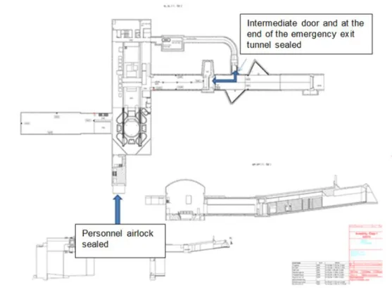
Figure 2-1 illustrates the geographical area, marked in red, in which dismantling and demolition of the Ågesta plant will occur. After clearance measurements and approval from SSM, the rock cavern will be sealed off with concrete casting, as the owner has no further use of it. The facility will be sealed off at the personnel airlock, at the intermediate door and at the end of the emergency exit tunnel, see figure 2-2. Ventilation shafts will also be sealed as well as all sewer lines.
16
Figure 2-2 The facility will be sealed off at the personnel airlock, at the intermediate door
and at theend of the emergency exit tunnel (marked in the figure). Ventilation shafts will
also be sealed as well as all sewers.
2.1.1. Brief description of Ågesta
Ågesta was the first reactor of its kind in the world and led the way for reactor develop-ment in Sweden with the use of natural uranium as fuel and heavy water as moderator. Ågesta was mainly used for supplying district heating, with an approximate thermal out-put of 55 MW, to the nearby community Farsta, located south of Stockholm. A small part of the production, 10 MW, was used to produce electrical power. After 1970 the core was redesigned, and Farsta received 68 MW heat and the grid 12 MW electricity.
On the 2nd of June 1974 Ågesta was shut down because of financial reasons. The heavy water inventory was sold to Canada and transported there later that year. Used fuel was removed and is stored in Clab2. The Ågesta facility is currently in care and maintenance
operation, which means that there is no fuel present and the reactor is shut down. Besides fuel and heavy water, two steam generators have been removed, and the facility’s opera-tion today includes maintenance, regulatory controls and radiological area control.
Buildings and components
Note that the following sections describe only the buildings and components relevant for the decommissioning. The facilities which house the turbines, laboratory, waste water
17
processing station and office buildings are located outside the rock cavern and are not in-cluded in the decommissioning. An application for the decision of free release of those buildings is currently being reviewed by SSM.
Rock cavern
The rock cavern is where the reactor, auxiliary systems, control room, ventilation system and switchgear are located. On top of the mountain there is the cooling tower (only one remaining) as well as inlets and outlets for the former ventilation system. The Expansion Duct, a part of Ågesta’s pressure control system, extends from the reactor at a 90 degree angle, and the transport tunnel extends at a 90 degree angle in the opposite direction. The control system, the switchgear and the ventilation systems are located outside the pressure-retaining steel liner but are connected to it.
Personnel areas are also located in the rock cavern. These areas will be rebuilt during 2019 to ensure sufficient capacity for the decommissioning personnel teams. These in-clude the office, laboratory and changing rooms. Water processing outside the controlled area will be performed using communal resources, and water processing in controlled area will be managed by using portable containers. Electricity, ventilation and other func-tions will be replaced in the rebuilt areas.
Containment (in rock cavern)
The rock cavern is clad in a pressure-retaining steel liner and these barriers function to-gether as the facility’s containment.
The reactor pressure vessel and two steam generators remain inside the containment.
Security boundaries
The entire rock cavern is within the monitored or ”protected” area of Ågesta. The con-tainment belongs to the “protected” area, the first security boundary level. Contamination is only expected in the protected areas.
Technical data
Relevant technical data on the Ågesta facility is summarized in Table 2-1. Table 2 -1 Technical data for the Ågesta reactor
Unit Value
Main supplier ASEA
Reactor Pressure Vessel Degerfors
Moderator
Heavy water (total amount) Ton 74
Time
Construction start Year 1 956
18
Volumes
Total construction in mountain m³ 30 000
Concrete inside containment m³ 3 182
Pressure-retaining steel liner
Length m 60
Width m 45
Height m 26
Steel liner thickness mm 4
Reactor plant
Thermal power to Farsta MW 55 (68)
Electric power to grid MW 10 (12)
Reactor pressure vessel
Height (maximum) mm 6 000 Inner diameter mm 4 555 Wall thickness mm 70 RPV weight kg 293 900 Control rods Weight kg 1 811
Number (total used) 30
Transport tunnel Length m 56,5 Width m 5,8 Height m 6,1 Expansion duct Length m 37 Width m 9
19
2.2. Ventilation systems and the treatment of gaseous and
air-borne wastes
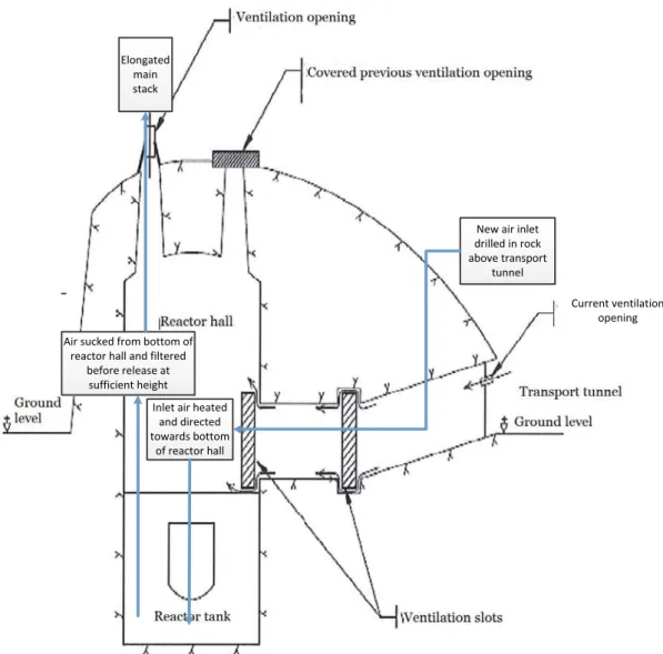
A new ventilation system is planned for the dismantling and demolition work. The system will be designed so that it can be used during the entire decommissioning project. The de-tailed design of the system will be carried out in continuous dialogue with SSM to ensure that relevant monitoring and/or other requirements are met. A general description is pre-sented below and illustrated in figure 2-3. A preliminary flow diagram is prepre-sented in ap-pendix 3.
The main stack used previously was dismantled and sold after the reactor was shut down, leaving only a short stack structure present. In the new ventilation system, this stack will be extended to achieve a sufficient exhaust release height, about 5-10 meters above the mountain top. The previous air inlet is today covered and will not be used for the new ventilation system. This is due to the fact that the Fire Brigade conducts fire-fighting ex-ercises in close proximity to the old air inlet, and hazardous chemicals are present in the area. Instead, a new ventilation inlet will be made through the rock into the transport tun-nel.
Height m 5
Fuel
20
Current ventilation opening
Inlet air heated and directed towards bottom
of reactor hall
New air inlet drilled in rock above transport
tunnel
Air sucked from bottom of reactor hall and filtered
before release at sufficient height
Elongated main stack
Figure 2- 3 Overview of planned (in blue) modernized Ågesta ventilation as well as existing (in black) ventilation.
The new ventilation systems serves three functions:
to ensure that occupational safety limits are not exceeded in order to maintain a healthy working environment for personnel,
to minimize the risk of spreading contamination inside and outside the facility and, in case of fire,
to evacuate smoke and fumes,
The ventilation system will be designed, so that the air flows towards spaces where risk of airborne contamination is increased and airflow is directed towards the point of re-lease.
The ventilation system’s exhaust air will flow through the existing piping on the top of the mountain. As the chimney has already been dismantled and removed, the existing pip-ing will be extended by to achieve a suitable release height, about 5-10 meters above the
21
mountaintop. Any airborne radioactive effluents will pass through the particle filters placed in the ventilation system before the release point (see figure 2-4).
The ventilation system will include isokinetic collection equipment to collect samples in order to monitor release of tritium and other isotopes. If the sampling system is out of ser-vice, mobile or manual measurement equipment will be used.
Figure 2-4 A principle scheme over a new monitoring system in the main stack. Spent filters from the ventilation system will be treated as solid waste.
It should be noted that the last time any fission took place in the Ågesta reactor was 1974. Short-lived radioactive gaseous isotopes such as noble gases, iodine, etc., are no longer present as they have decayed during this time. Any potential airborne contamination would therefore be caused by mobilising previously non-airborne contamination. Ventilated containment tents can be used when performing local demolition or disman-tling work. These tents will be ventilated with their own fans and air will be filtered be-fore being returned to the surrounding facility or directly to the ventilation system. Such local ventilation may also be required for the removal of hazardous materials such as as-bestos. Another option available is to use portable filters as an alternative or as a comple-ment to containcomple-ment tents, which can be especially beneficial when the demolition/dis-mantling work is performed during shorter time intervals in smaller areas.
Chapters 3 and 6 describe the consequences of a release of the entire inventory of radio-active material from Ågesta. This applies as the potential worst case for an unfiltered re-lease through the ventilation system during the decommissioning project. As rere-leases have been shown to have not exceed dose rate limits on citizens in a third country, no fur-ther analysis of discharges through the ventilation system have been performed.
22
2.3. Liquid waste treatment
There is no water treatment facility for contaminated water at Ågesta, so all water dis-charged from controlled areas will be handled in closed systems. Contaminated water will be collected in IBC3or similar containers and be transported to an approved water
treat-ment facility, for instance SVAFO’s evaporation facility. All activities which require wa-ter in potentially contaminated areas will be kept at a minimum.
2.4. Solid waste treatment
The decommissioning of Ågesta will provide two main challenges – the logistics of waste management in confined area, and the transition from care and maintenance operation, to an active decommissioning phase.
The challenge in establishing the waste management system for the decommissioning project is logistical as well as operational. There are no permanent solid waste treatment facilities available, therefore on site mobile solutions and temporary modifications will be applied as needed. Some of the challenges can be mitigated by adapting the facility to the decommissioning phase e.g. the rebuilding the personnel areas to allow for a larger work force.
Some areas inside the rock cavern will be made available for storage and handling of waste, e.g. the expansion tunnel with a floor area of 9x37 meters and a ceiling height of 5 meters. An area outside the rock cavern is planned for buffer storage of packaged waste awaiting transportation.
Sweden has an established system for the disposal of radioactive waste, see appendix 1, which includes transportation. This means that there is experience available in the pro-duction of waste packages for operational waste that are suitable for disposal in approved and operating disposal facilities. This system can be suitably adapted for use in the Ågesta decommissioning program.
The general sequence in all solid waste management performed in the decommissioning project is:
1. Dismantling, e.g. cutting a section of a system or segmenting an internal compo-nent.
2. Collection & Segregation, e.g. sorting the generated waste based on the waste type, contamination level, etc.
3. Treatment, e.g. decontamination, stabilization, compaction etc. The need for this step is based on several factors and only performed if it is deemed that it adds value to the entire waste management chain.
4. Conditioning, e.g. packaging the waste in its final container. In Ågesta, some waste may be conditioned on site using mobile equipment and waste that requires further handling may be conditioned at the Studsvik site where it is prepared for interim storage.
5. Measurement of the radiological parameters, such as nuclide-specific contents, dose rates and surface contamination levels. This data is required for transporta-tion but further measurements may be necessary after conditransporta-tioning at the Studsvik site.
23
6. Temporary storage of waste awaiting transportation in a designated area outside the rock cavern.
7. Transport of waste container to the Studsvik site.
8. Possible conditioning of waste and measurements after conditioning.
9. Storage until the waste package is ready to be accepted at a disposal site at the existing interim storage facility at Studsvik site.
10. Transport to the disposal site, mainly using the SKB transport system. 11. Final disposal.
The sequence described above is not applicable in its entirety to waste that is treated off-site, e.g. in the case of melting or incineration of waste. Additional information about the waste streams as well as radiological levels is presented in chapter 5.
2.5. Containment
Activity present in Ågesta is largely bound to a material, but may be released during dis-mantling and demolition. An example could be the oxide coating that normally occurs on the inside of the system, which is protected until the process of dismantling has begun. Releases to air goes by the ventilation system and are minimised using filtration, see sec-tion 2.2.
Active components will be handled within the rock cavern to contain any risk of radioac-tive release outside the building. Dismantled components and building waste will be free released, after clearance, or sorted according to activity levels and then packed according to clearly defined routines. Contaminated water will be handled within the rock cavern and transported to an approved water treatment facility, see section 2.3.
For all nuclear power plants in Sweden there is an established system, the Swedish sys-tem, managed by SKB AB on behalf of the nuclear industry in order to ensure the safe disposal of all nuclear waste and fuel, see appendix 1.
For each waste type a description of the specific waste handling process from the time the waste is produced until it has been finally deposited into SFR or SFL is required, includ-ing interim storage criteria and transportation criteria. This is a requirement from SSM. For external treatment facilities, the acceptance criteria for waste to be treated are estab-lished by the supplier performing the treatment, and the requirements must be met by the waste producer before the waste is treated. The supplier will package any residual radio-active waste in accordance with the associated waste type description4.
In accordance with the above, one of the most important documents, ensuring well-planned and safe waste management is the waste handling plan for the decommissioning. This plan forms part of the safety analysis report (SAR). The specific waste type descrip-tions will also be produced, both at Ågesta (as the waste producer) at the Studsvik facility and SFR. Before a new type of waste is produced, the waste type description is submitted to SSM for review and approval.
4 Note that the owner of the waste sent for treatment is still the owner of any secondary waste generated during the treatment
24
3. Release of airborne radioactive effluents in
normal conditions
3.1. Authorisation procedure in force
3.1.1. Legislation on nuclear activities
The Act on Nuclear Activities SFS 1984:3 and the Radiation Protection Ordinance (SFS 2018:506) with instructions for the Swedish Radiation Safety Authority (SFS 2008:452) have been translated into English and can be found on the SSM website (www.ssm.se). The Radiation Protection Act (SFS 2018:396 is not yet published in English. These acts and the ordinance, together with the Ordinance on nuclear activities SFS 1984:14 and the Radiation Protection Ordinance (SFS 2018:506), stipulate the boundaries for all nuclear activities in Sweden. SSM has developed regulations (SSMFS) to provide a more detailed framework for e.g. nuclear power plants. Some of the regulations are available in English. SSM is responsible for regulating radiological safety and security at all nuclear licensed sites in Sweden. SSM issues regulations and permits and verifies that the licensee is in compliance with these. The objective is to optimise radiation protection for personnel and the public while limiting releases of radioactive substances to the lowest possible reason-ably practicable levels.
The most important regulations and licence conditions with respect to this are:
SSMFS 2008:1: The Swedish Radiation Safety Authority’s Regulations and Gen-eral Advice concerning Safety in Nuclear Facilities
SSMFS 2018:1 The Swedish Radiation Safety Authority´s regulations concerning basic provisions for practises involving ionising radiation subject to mandatory licensing.
SSMFS 2018:3: The Swedish Radiation Safety Authority’s regulations and gen-eral advice concerning clearance of materials, rooms, buildings and land in prac-tices involving ionising radiation
Radioactive releases from nuclear facilities that are being dismantled and decommis-sioned are not specifically regulated in any SSMFS at present, but have been issued as (future) licensing conditions in [8]. These state, among other conditions (not verbatim);
Discharges of radioactive substances from nuclear facilities and exposure of the environment to ionising radiation shall be limited as far as reasonably practicable considering available technology as well as social and economic factors.
The effective dose to any individual in the reference group resulting from an an-nual discharge of radioactive substances to water and air from all facilities situ-ated within the same geographical area shall not exceed 0.1 mSv. If the estimsitu-ated dose is 0.01 mSv or higher per calendar year, realistic calculations shall be per-formed regarding the most affected area. The calculation method shall be in ac-cordance with SSMFS 2018:1.
Discharges of radioactive substances from nuclear facilities to air and water shall be checked by means of measurements, as far as reasonably practicable.
25
Environmental surveys shall be conducted in the vicinity of a nuclear facility ac-cording to a survey scheme approved by SSM.
The licensee shall have a documented plan for limiting, reducing and monitoring releases of radioactive substances to the environment.
Requirements on reporting information about releases to the environment to SSM are specified in licence condition 26.
3.1.2. Discharge limits and associated requirements for decommissioning
In Sweden there are no discharge limits in Bq for the time before the envisaged disman-tling operations or the dismandisman-tling operations themselves. Instead, the annual dose to the public is estimated in accordance with 2-3 § SSMFS 2018:1 from all nuclear facilities sit-uated in the same area to verify that it does not exceed 0,1 mSv.
3.2. Technical aspects
Small or no measurable amounts of airborne radioactive effluents are expected to be dis-charged during dismantling (Tritium is likely to be measurable in small amounts). The statement is based on measurements during the recent dismantling of the research reactor R2 at the Studsvik site. Measurements of particle filters, placed at the different release points at R2, have been performed. No gamma-emitting nuclides have been detected in the nuclide specific measurements. In the non-nuclide-specific measurements, a small quantity of alpha-emitting nuclides was detected. Up to 10 kBq have been measured for one year. A conversion of the alpha-release to dose can be performed by applying the dose factor for Am 241, which is 8,8 × 10⁻¹⁵ Sv/Bq. An annual release of 10 kBq Am-241
thus corresponds to an effective committed dose to an infant in the most exposed repre-sentative family of 8,8 × 10⁻¹¹ Sv or 8,8 × 10⁻⁸ mSv. Discharge of airborne radioactive
ef-fluents during the dismantling of the R2 reactor was consequently negligible. The dis-mantling of the reactor at Ågesta will take place inside the leak-tight steel layer within the rock cavern and there is no reason to assume that measurable amounts of airborne radio-active effluents will be discharged during dismantling.
Best available technology will be used to reduce the release of radioactive effluents from the systems, components or structures that are taken apart and subsequently packed. When components are cut into pieces, local filters and filters in the ventilation system will be used. Areas where cutting is performed will be separated from other areas. The release point of the ventilation system is situated on top of the rock cavern. Any re-lease of airborne radioactive effluents would pass the particle filters installed in the venti-lation system before the release point.
3.2.1. Origins of the radioactive effluents, their composition and
physico-chemical forms
All radioactive waste materials at Ågesta are situated within the rock cavern and inside pressure-retaining steel liner.
Radioactivity originates from the period of power operation and was mainly produced in the following processes:
26
Neutron activation of materials close to the core. For example activation of silver in the control rods, activation of cobalt in internal components and activation of deuterium in the cooling water.
Neutron activation of corrosion products from surrounding systems that followed the cooling media through the core and e.g. deposited on system surfaces. Contamination of systems and construction parts. For example tritium
contamina-tion of the refuelling machine and tritium contaminacontamina-tion of concrete structures. Radioactivity from contamination or activation is bound in systems, components or constructions. All waste is solid and there is no radioactive waste in gaseous or liquid form present at Ågesta. Parts of the plant with relatively high amounts of radioactivity in-clude the reactor pressure vessel, the biological shield, control rods, refuelling machine and portions of the primary system. The six nuclides with the highest radioactivity are listed in table 3-1. The reference date for the inventory is 1st of January 2020 and in-cludes 29 nuclides in total. Only nuclides that are expected to exceed the limit values for conventional waste treatment have been included in the total inventory.
Table 3-1. The six nuclides with the highest radioactivity at Ågesta as of 1st of January 2020. Nuclide T1/2 Activity (Bq) Ni-63 98.7 y 4.6 × 10¹³ H-3 12.3 y 4.2 × 10¹³ Ag-108m 438 y 1.9 × 10¹² Ni-59 76.0 ky 5.3 × 10¹¹ Co-60 5.27 y 2.7 × 10¹¹ C-14 5.70 ky 9.0 × 10¹⁰
As previously mentioned, no releases of radioactive effluents are expected during the dismantling of the Ågesta reactor. However, assumed release fractions of the six nuclides with the highest radioactivity were applied to calculate a rough conservative estimate of the dose to a representative person. A release fraction of 10-7 per year was assumed for
five of the nuclides presented in the table (all nuclides except tritium). Measurements per-formed during segmentation of internal parts (e.g. steam separators and core spray) at unit 3 at the Oskarshamn NPP in 2012 resulted in a release fraction of 10-7 for cobalt during
segmentation. No discharges to the atmosphere were observed during the actual cutting, but the activity remained in the pools and was released later when water was removed and areas dried.
Tritium can be assumed to be more volatile than the other nuclides and according to IAEA TECDOC 1162, the release fraction of tritium is 500 times that of Co-60. Even though the release fractions are estimated for a fire taking place, the relationship is sumed to be the same during segmentation. The release fraction of tritium is therefore as-sumed to be 5 × 10⁻⁵ of the total inventory per year. Assumptions of the release of
27
Table 3-2. Assumption of annual release of airborne radionuclides.
Nuclide T1/2 Activity (Bq) Ni-63 98.7 y 4.6 × 10⁶ H-3 12.3 y 2.1 × 10⁹ Ag-108m 438 y 1.9 × 10⁵ Ni-59 76.0 ky 5.3 × 10⁴ Co-60 5.27 y 2.7 × 10⁴ C-14 5.70 ky 9.0 × 10³
3.3. Monitoring of discharges
Isokinetic measurements of aerosols and tritium will be performed of the air that exits the rock cavern via the main stack, see figure 2-4. Aerosol and tritium filters will be installed in by-pass lines adjacent to the main stack. The filters will be replaced once a month and analysed for the presence of radionuclides.
All analyses will be performed at an external laboratory. The collection is continuous. To-gether with the total volume that has passed through the filters and the average air flow in the main stack it is possible to calculate the discharges to the air.
Automatic alarms will be installed to detect low flow in the main stack and low flow in the sampling loops.
3.4. Evaluation of transfer to man
3.4.1. Models, including where appropriate generic models, and parameter
values used to calculate the consequences of the releases in the
vicinity of the plant
If the assessed maximum exposure levels from discharges during normal conditions to adults, children and infants in the vicinity of the plant are below 0.01 mSv per year and there are no exceptional pathways of exposure, e.g. involving the export of foodstuffs, then no data on effective dose in other affected member states are required if doses to the reference group in the vicinity of the plant are provided.
As previously mentioned, no releases of radioactive effluents are expected during the dis-mantling. However, the releases as presented in table 3-2 have been used in a rough con-servative estimate of the dose to a representative person. The concept of representative person is defined in ICRP publication 101.
A national effort has recently been made to determine dose factors for the different re-lease points at seven nuclear sites in Sweden [15]. Dose factors have been proposed
28
(awaiting final approval by SSM) for the release of 1 Bq of a specific radionuclide and the factors are expressed in Sv/year per Bq/year. The dose models and the dose factors are established according to chapter 5 in SSMFS 2018:1, which implements ICRP 101 and dose coefficients recommended by ICRP. Once applied, the result is the annual effec-tive committed dose for the highest exposed individuals at the maximum 100th year of annual radionuclide releases. No specific dose factors have been determined for the Ågesta site. The closest facility for which dose factors have been determined is Studsvik which is approximately 70 km away, and the factors for a fictive release point at Studsvik [16] [17] have been used for estimation of doses to the public from aerial discharges from Ågesta during normal operation. Appendix 4 presents an analysis of the usage of dose factors from the PREDO model for the Studsvik site and it is shown that lifestyle and en-vironmental aspects in the area surrounding Ågesta do not differ significantly compared to the area surrounding Studsvik.
Below follows a short description of models used in PREDO:
The methodology for atmospheric dispersion has been developed by the Swedish Meteor-ological and HydrMeteor-ological Institute (SMHI) and it is based on a local-scale analytical Gaussian model. Five-year weather data statistics was utilized to derive time-averaged surface air concentrations and deposition fields (both wet and dry deposition). The model uses hourly pre-processed meteorological data based on similarity theory. Re-suspension is not considered in the model.
Food chains, inhalation, external exposure (from ground and from cloud) and living hab-its (such as time spent outdoors) are determined for three age groups i. infants, ii. children and iii. adults, belonging to the following families:
Average family
Farmer (general) family Farmer (dairy producer) family Fisherman family
Hunter family Vegetarian family
In the food chain model various foods are divided into different groups and each group is treated in a specific manner in the calculations. The following groups are included for food:
Aquatic food types Wild berries Crop types Herbivores/Game Meat types Milk types Mushrooms Eggs
To obtain the fraction of a food type that is locally produced, different studies on con-sumption and/or on import and export have been used.
Dose factors were determined for all release points at Studsvik, and the so called fictive release point showed the highest dose factors. Dose factors were determined for all age
29
groups and for all different families and conservatively, the highest determined dose fac-tors for each of the six radionuclides in table 3-1 are applied here for the estimation of ef-fective dose during Ågesta decommissioning. For all radionuclides except H-3, the high-est dose factors are found for the infant in the vegetarian family. For H-3 the infant in the farmer or dairy farmer family show the highest values.
Table 3-3 shows the dose factors, obtained from the PREDO result report for Studsvik [17], used for calculations of effective committed dose during decommissioning of Ågesta.
Table 3-3 Dose factors used for estimation of effective committed dose during decommis-sioning of Ågesta. The highest estimated dose factors for each radionuclide are used.
Nuclide Dose factor (Sv/Bq) Description of dose factor
Ni-63 1.86 × 10⁻¹⁷ Infant, vegetarian family
H-3 7.36 × 10⁻²⁰ Infant, farmer or dairy farmer family
Ag-108m 1.38 × 10⁻¹⁵ Infant, vegetarian family
Ni-59 8.68 × 10⁻¹⁸ Infant, vegetarian family
Co-60 6.05 × 10⁻¹⁶ Infant, vegetarian family
C-14 1.30 × 10⁻¹⁷ Infant, vegetarian family
A comparison of dose factors for the six nuclides analysed was performed for the three age groups and all the release points at the seven Swedish nuclear sites. In all cases ex-cept one the dose factors used here were the highest. The exex-ception was found for the dose factor of C-14 at the release point Ustore at the nuclear fuel manufacturing facility in Västerås. That dose factor is twice as large as the factor used here. However, the dose fac-tor for the Studsvik site are still used for the estimation of committed effective dose, see Appendix 4.
3.4.2. Evaluation of the concentration and exposure levels associated with
the envisaged discharge limits for the dismantling operations cited
in 3.1 above:
The committed effective dose is calculated by multiplying the dose factor in table 3-3 with the conservative assumption of annual release of airborne radionuclides in table 3-2. The results are shown in Table 3-4.
In summary, the committed effective dose to an infant in an “imaginary conservative family” (combination of dose factors for the vegetarian and the farmer/dairy farmer fami-lies) is conservatively estimated to be 5.2 × 10⁻¹⁰ Sv (or 0.00000052 mSv). The above
cal-culation shows that it is not feasible that the representative person in the vicinity of the plant can receive an annual committed effective dose greater than 0.01 mSv during dis-mantling. No exposure levels in other Member States are therefore estimated or presented in this report. Nor are there any other installations from which discharges need to be con-sidered in conjunction with those from the installation in question.
30
Table 3-4 Dose factors used for estimation of effective committed dose during decommis-sioning of Ågesta. The highest estimated dose factors for each radionuclide are used. The committed effective dose is calculated by multiplying the dose factor by the assumed annual release in table 3-2. The highest estimated dose factor for each radionuclide was used.
Nuclide Committed effective
dose (Sv) Ni-63 8.6 × 10⁻¹¹ H-3 1.6 × 10⁻¹⁰ Ag-108m 2.6 × 10⁻¹⁰ Ni-59 4.6 × 10⁻¹³ Co-60 6.5 × 10⁻¹¹ C-14 1.2 × 10⁻¹³ Total 5.2 × 10⁻¹⁰
31
4. Release of liquid radioactive effluents in
nor-mal conditions
4.1. Authorisation procedure in force
See Section 3.1 for a general description of legislation and authorisation procedures.
4.2. Technical aspects
Under normal circumstances, the use of water will be minimised during dismantling of Ågesta. There are no water pipes within the area where radioactive waste is present and no drains from that area.
In special circumstances, such as decontamination of personnel, water may be used. In such an event, waste water is collected in tanks that can be transported to Studsvik for waste water treatment.
4.3. Monitoring of discharges
Measurements are currently performed to verify that water inside the rock cavern but out-side the pressure-retaining steel liner does not penetrate the steel. There are 35 penetra-tions in the steel liner to handle drainage water. The water is led through the steel liner, inside closed pipes, and then it is collected in a drainage pit before it continues in a ditch to lake Orlången. Water that passes through the containment is not exposed to its atmos-phere. Measurements of the water in the drainage pit and of the water, as well as the sedi-ment, in the ditch verify the absence of radionuclides in the drainage water. This monitor-ing will continue while the reactor is bemonitor-ing dismantled.
4.4. Evaluation of transfer to man
As stated in chapter 4.2, no discharge of water is expected during dismantling. No evalua-tion of the transfer to man has therefore been performed.
32
5. Disposal of solid radioactive waste from the
installation
5.1. Solid radioactive waste
This chapter describes the Swedish requirements governing the management of radioac-tive solid waste and how the waste arising from the decommissioning of Ågesta will be managed. The chapter supplements the information provided in chapter 2.4.
The licensees are responsible for the nuclear waste arising during operation and decom-missioning of a nuclear facility. This responsibility ceases once the waste has been placed in a final repository that has been finally sealed.
Swedish regulations require the waste generator to produce a waste handling plan as well as a specific description of each waste type. Both the waste handling plan and the waste type descriptions (WTD) undergo safety reviews and form part of the safety analysis re-port for each facility where the waste is handled. This includes the facility of origin, in this case Ågesta, as well as any offsite treatment facilities and the final repository. The WTD describes the handling sequence, from the time the waste is produced until it has been finally deposited in SFR (Final repository for short-lived radioactive waste) or SFL (Planned final repository for long-lived radioactive waste). The WTD lists the relevant waste acceptance criteria (WAC) together with a description of how compliance with the WAC is verified. Before a particular waste type can be produced and disposed of at the SFR-facility, the WTD must be approved by the Swedish Radiation Safety Authority. The system for managing radioactive waste in Sweden is described in chapters 2.4-2.5 and appendix 1.
5.1.1. Categories of solid radioactive waste and estimated amounts
The initial sorting of materials, buildings and site areas from a radiological and hazard perspective as well as the estimated quantities is derived from previous studies. Taking into account the information compiled in previous studies, operational records and other relevant information, the waste expected to arise during the dismantling and demolition has been defined and quantified for the purposes of this report.
The waste is further divided into different waste streams: Metal, Combustible and Other radioactive solid waste (concrete, sand, etc.).
Levels of radioactive waste are defined based on the content and half-life of the respec-tive radionuclides in the waste.
In Sweden there are five levels of low and intermediate level radioactive waste defined in SKB’s waste manual [4]. These levels dictate how radioactive waste is disposed of.
Short-lived very low level waste (VLLW): Contains short-lived radionuclides with
half-life less than 31 years. The dose rate on the waste container (and unshielded material) < 0.5 mSv/h. This waste is often secondary waste (such as gloves, protective clothing and equipment). This waste meets the acceptance criteria for final disposal in BLA (Rock
33
vault for low level waste in SFR) or may be disposed in a surface repository. VLLW which fulfils acceptance criteria can be sent to facility for incineration. Disposal in a sur-face repository is not an option for waste originating from Ågesta.
Short-lived low level waste (LLW): Contains short-lived radionuclides with half-life less
than 31 years. The dose rate on the waste container (and unshielded material) < 2 mSv/h. Long-lived radionuclides with half-life greater than 31 years are present in limited quanti-ties. The waste meets the acceptance criteria for final disposal in BLA (Rock vault for low level waste in SFR).
Short-lived intermediate level waste (ILW): Contains significant quantities of
short-lived radionuclides with half-life less than 31 years. The dose rate on the waste container < 500 mSv/h for disposal in Silo and < 100 mSv/h for disposal in BMA (Rock vault for intermediate level waste). Long-lived radionuclides with half-life greater than 31 years are present in limited quantities. The waste meets the acceptance criteria for final disposal in Silo or BMA.
Long-lived low level waste: Contains long-lived radionuclides with half-life greater than
31 years and in significant quantities greater than the limits that apply to short-lived waste. No dose rate limit for disposal has been specified. The waste will be disposed of in SFL (Final repository for long-lived waste).
Long-lived intermediate level waste: Contains long-lived radionuclides with half-life
greater than 31 years and in significant quantities greater than the limits that apply to short-lived waste. No dose rate limit for disposal of this waste has been specified. The waste will be disposed of in SFL (Final repository for long-lived waste).
Table 5-1 lists the total quantity in tons for each waste level and stream for Ågesta and is presented in figures 5-1 which depicts the quantities of the waste levels projected to arise during decommissioning of Ågesta.
Table 5-1 lists the total quantity in tons for each waste level and stream for Ågesta and is presented in figure 5-1 which depicts the quantities of the waste levels projected to arise during decommissioning of Ågesta.
Level/Stream Metal Combustible Other Total (tons)
LLW (short-lived) 100 100 250 450
ILW (short-lived) 200 0 0 200
LLW (long-lived) 0 0 50 50
ILW (long-lived) 300 0 0 300
34
Figure 5-1. Decommissioning waste sorted by waste level from the SKB waste manual (tons).
The primary waste streams are described below:
Metallic waste
The metallic waste is comprised of both long-lived and short-lived radioactive waste, where the long-lived waste consists solely of reactor internals that have been neutron-ac-tivated. The metallic waste originates from:
Process systems Steel structures Electrical equipment Large components
Process systems and other sources of metallic waste will be dismantled and when neces-sary cut into smaller segments.
Metallic waste is primarily treated through melting. If not melted it is sent to SFR or SFL.
Combustible Waste
Combustible waste is generated mostly as secondary waste from the dismantling and de-commissioning activities. Secondary waste includes for instance contaminated protective clothing, gloves, plastic for example.
Other Solid Waste
Other radioactive solid waste is comprised primarily of concrete and sand. Concrete is present in conventional building material and as radiation shielding in the biological shield. ILW concrete is expected to arise solely from the demolition of the biological shield.
35
5.1.2. Processing, packaging and disposal
Most requirements for processing and packaging of radioactive solid waste are deter-mined by the intended disposal. If the waste will be disposed of in a repository then the waste acceptance criteria must be met, which may entail specific treatment and packag-ing. If the waste is intended for clearance then it may be subject to treatment before this can take place. See chapter 2.4 for more information.
More than one disposal option may be applicable for several of the waste streams. The appropriate option is selected based on several factors, for instance, radiation protection, logistics, environmental impact and risks.
In Ågesta, some waste may be conditioned onsite and other which require further han-dling may be conditioned on the Studsvik site to be prepared for interim storage.
Processing
Radioactive solid waste is processed or treated with the objective of ensuring that it can either be cleared or rendered compliant with waste acceptance criteria for disposal. This treatment can also include volume reduction to maximize packing efficiency in the geo-logical repository. Processing includes segregation of waste in different streams and lev-els, segmentation of piping and components, decontamination, fixing of loose surface contamination and compaction. Melting or incineration at an offsite facility is also possi-ble.
Incineration is performed of organic radioactive waste at the Cyclife facility (see 5.3 for more information). It provides an efficient volume reduction and destroys chemically re-active substances. The portion of waste from Ågesta that is combustible and has a contact dose rate less than 0.5 mSv/h may be sent for incineration. Nuclide-specific activity con-centration limits must also be met in order for the waste to be acceptable for incineration. Secondary waste (ash) produced as a result of incineration will be disposed of as low-level waste.
Melting of waste reduces its volume and surface as well enables verification of the activ-ity contents for an object. Activactiv-ity not separated in smoke or slag will be homogenously distributed, and activity is bind in the metal structure. Material suitable for melting is steel, aluminium, copper, brass and lead. Melting is performed at the Cyclife facility at Studsvik. Material for melting is mainly metal from components, process systems and other metallic parts.
Packaging
Packaging criteria for radioactive solid waste are dictated by both transportation and dis-posal requirements. Low level waste is transported and disposed of in ISO containers or other approved containers that meet specified standards. Short-lived intermediate level waste is packaged in steel or concrete moulds and long-lived intermediate level waste is packaged in steel tanks.
Disposal
The options available in Sweden to dispose of radioactive solid waste are in the geologi-cal repository (SFR) or in a surface repository. The later one does not apply to