12
M o d er n S t er e oto M y
Stereotomy
ProgramThe task at hand was to design an optimized structure. The location was the first railway station ever built, between Liverpool and Manchester. The old wapping tunnel and station were going to transform into a dance hall, a gallery and a foyer. I chose to focus on creating a roof structure over the latter.
modern
Concept
The idea was to construct an optimized all-compression structure. A vault in three dimensions. A shell which stood for itself without any use of binding material. It’s based on the idea of both horizontal and vertical equilibrium and uses software developed by the BRG (Block Research Group). With ancient knowledge combined with modern tools we are able to explore shapes wich weren’t possible before.
The art and science of cutting three-dimensional solids into particular shapes - Collins English Dictionary.
No glue needed
Close-up of the self-bearing shell structure. Mdf, hardened gypsum, 1:50 13 o L A S J Ö B er G - A P P L I C At I o n Course: Focus: Location: Software: Eximinator: Working method: Optimized structures Optimisation, modelmaking Liverpool, England
Rhinoceros, Rhinovault, Grasshopper Morten Lund, Peter Christensson Individually in studios of four.
* the Block research Group (BrG) at the Institute of technology in Ar-chitecture at etH Zürich is led by Prof. dr. Philippe Block and dr. tom Van Mele
14
M o d er n S t er e oto M y Rhinovault
The software used is a plug-in to the 3D modeler software Rhinoceros developed by Philip Block research gruop, BRG*. It provides an intuitive form-finding method, adopt-ing the same advantages of techniques such as graphic stat-ics, but offering a viable extension to fully three-dimension-al problems. The form of the shell structures is determined from the original geometry and the boundary conditions.
Grasshopper
Together with Grasshopper a 3D-model was created. Ad-ditional attributes could then be changed as needed. The thickness of the shell is decided upon its distance from the ground and the vossoir geometry derives from the original geometry.
3D-printing
A physical model was produced with a gypsym 3D-printer. The high accuracy of the printer was a prerequisite for the uniqe vossoir pieces to fit together.
Conclusion
There are many diffrent methods to apply when designing a gridshell. This is one of them. Working with computer models vs physical model is a great way to see what works and what doesn’t. The question that remains is; how could we translate this into useable architecture?
15 o L A S J Ö B er G - A P P L I C At I o n
16 17 O L A S J Ö B ER G - P O R T F O L I O M o d er n S t er e oto M y
Force diagram
Graphic statics illustrating the horizontal equilibrium of the three dimen-sional structure projected onto a two dimendimen-sional surface.
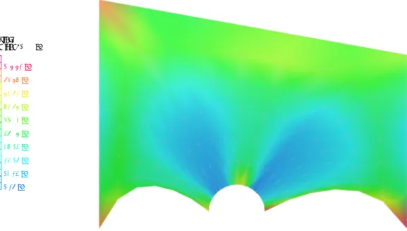
Mesh showing the compression in the structure. Calculated with a dead-load of 1000 kn.
Actual model assembled without binding material. the model is made out of 60+ unique vossoirs individually casted with a gypsum 3d-printer.
Resultant Dead load: 1000 kN 108.82 kN 96.87 kN 84.92 kN 72.98 kN 61.03 kN 49.08 kN 37.14 kN 25.19 kN 13.24 kN 1.29 kN
18 19 O L A S J Ö B ER G - P O R T F O L I O M o d er n S t er e oto M y
Individually placed voussoir pieces
Surrounding structure made from MdF-wood determining the boundary conditions.
Supporting styrofoam structure made with a four axis CnC-mill. the vousssoirs are individually placed in its position.
removeable bottom
Assembly
Video
Snapshots from video of the inflicted collapse of the structure. https://www.instagram.com/p/Bc5d6kPleqL/?taken-by=olert