03-EPFL
Page 1 of 65
Contract TST3-CT-2003-505831 Authors: N. Bueche, J. Dumoulin, T.
Sedran, J.-P. Marchand, D. Kokot, B. Kalman et al.
File : Deliverable2.2 Synthesis report-Rev5.doc
NR2C - New Road Construction Concepts
Work Package 2 – Interurban infrastructures
Deliverable 2.2
Concept and design of selected innovations for interurban
infrastructure
Synthesis reports
Modifications follow-up Ref draft date date of submitting to approval or date of approvalComments and/or brief description of the modifications Ex : “sending for approval to…”,“approved by …”
or “Comments from … dated …taken in account”
first Sent by e-mail to WP2 members for comments.
Comments deadline: at 12:00.
Sent by e-mail to Project Manager (B. Mahut)
Rev1 2007-04-26 First version for In2.4 with adoption of comments from B. Mahut 23 April
Rev2 2007-09-17 Innovation 2.1A completed; sent to partners for comments and completion
Rev3 Comments from KTI, BRRC and LAVOC included
Rev4 2007-11-20 Contribution from Eurovia and LCPC included. Innovation 2.1A modified.
Rev5 2008-01-08 Contribution from ZAG and VTI (innovation 2.4) included Rev6 2008-02-18 2008-02-21 Final version submitted to TMG+PMB approval
03-EPFL
Page 2 of 65
Contract TST3-CT-2003-505831 Authors: N. Bueche, J. Dumoulin, T.
Sedran, J.-P. Marchand, D. Kokot, B. Kalman et al.
File : Deliverable2.2 Synthesis report-Rev5.doc
TABLE OF CONTENTS
A - INTRODUCTION ... 3
B - EXECUTIVE SUMMARY ... 5
C - SYNTHESIS REPORTS OF THE DIFFERENT INNOVATIONS ... 6
C.1 Innovation2.1A: Development of high performance base layers with low cost materials and high percentage of re-use ... 6
C.1.1 Material characterisation and mix design ... 6
C.1.2 Laboratory performance of the mixes ... 7
C.1.3 Accelerated loading tests ... 8
C.1.4 Other tests related to ALT ... 12
C.1.5 Conclusions and recommendations ... 15
C.2 Innovation 2.1B: Crack-free semi-rigid pavement incorporating two industrials by-products ... 16
C.2.1 General scope of the innovation ... 16
C.2.2 Bibliographical search ... 16
C.2.3 Preliminary feasabily tests ... 19
C.2.4 Conclusions ... 26
C.3 Innovation 2.2: Roadway perception technology using the infrared know-how ... 27
C.3.1 State of the art ... 27
C.3.2 Study of measurement methods in situ for infrared properties ... 28
C.3.3 Study of a simplified model for atmospheric infrared transmission in fog for road meteorological conditions ... 30
C.3.4 Development of a infrared simulation tool for simplified road geometries... 32
C.3.5 Trials ... 33
C.3.6 Conclusions and recommendations ... 37
C.4 Innovation 2.3: New pavement maintenance technique aiming at enlarging the overall conditions of application ... 39
C.4.1 Organisation anf tasks ... 39
C.4.2 Rating trees ... 39
C.4.3 Rating tree for bituminous material ... 40
C.4.4 Rating tree for hydraulic bounded materials ... 42
C.4.5 Solution for bituminous material ... 42
C.4.6 Conclusions ... 43
C.5 Innovation 2.4: Improving the mechanical properties of a low noise section ... 45
C.5.1 Justification and background to the innovation ... 45
C.5.2 Identification of key points to improve ... 45
C.5.3 Wet skid resistance ... 46
C.5.4 Raw material ... 47
C.5.5 Production of test material ... 48
C.5.6 Test description ... 50
C.6 Results ... 52
C.6.1 Stability of block pavement ... 55
03-EPFL
Page 3 of 65
Contract TST3-CT-2003-505831 Authors: N. Bueche, J. Dumoulin, T.
Sedran, J.-P. Marchand, D. Kokot, B. Kalman et al.
File : Deliverable2.2 Synthesis report-Rev5.doc
A - Introduction
The highway traffic size and loads have been continuously increasing all over Europe. At the same time, the expectations of users have been growing. They need more safe, durable and comfortable highway surfaces which make their trips low-cost and do not accept frequent traffic disturbance due to road maintenance and rehabilitation. The obvious answer of the highway engineering to this challenge is the continuous development and improvement of highway construction, rehabilitation and maintenance techniques further.
The state-of-the art review of NR2C Work Package 2 on European highway innovations (Deliverable 2.1[1]) has clearly demonstrated the typical trends of innovative road construction, rehabilitation and maintenance which are as follows:
• the use of very high quality (premium) basic materials eventually with their special treatment, • the establishment of sophisticated construction, rehabilitation and maintenance techniques
utilising up-to-date scientific achievements,
• the development of special measures for enhancing traffic safety even in extreme conditions, • decreasing the whole life (life cycle) costs of road pavements by constructing long-life variants
with infrequent maintenance and rehabilitation need, and, consequently, minimal traffic disturbance,
• the wider use of industrial by-products in road engineering without reducing pavement performance,
• the wider use of recycling (eventually-re-use) of bound pavement structural layers in order to reduce the need for primary basic materials without jeopardising the performance of pavements,
• giving priority to low-energy pavement structural variants reacting to the ever increasing energy prices and the limited availability of crude oil supplies,
• there are some “blue sky” type innovations which utilise some new scientific results eventually coming from science areas far away from highway engineering.
Vision 2040 elaborated by Work package 0 can be considered as the basic document of NR2C project. It identifies the research areas the successful elaboration of which can have a significant contribution to the attaining of reliable, comfortable and safe roads of next-coming decades. The NR2C vision 2040 designates four main concepts for the road of the future. The innovations considered in WP2 all deal with solutions for one or more of the above concept needs, and mainly with the green infrastructure by reservation of rare resources via recycling and use of industrial by-products.
Innovation 2.1 A Design of high performance layer with raw material (EPFL-Switzerland, BRRC-Belgium, and other FEHRL-laboratories as VTI, KTI, DRI).
The goal is to evaluate if the growing share of recycled aggregate used in asphalt high stiffness base courses influences the asphalt mechanical properties. It is the aim of this study that no significant loss in asphalt fatigue, deformation and durability characteristics counterbalances the environmental and economic benefits coming from the use of recycled material. Comprehensive laboratory and Accelerated Loading Tests (ALT) are performed in the project.
Innovation 2.1B Crack free semi-rigid pavement incorporating industrial waste (LCPC-France)
The goal is to evaluate if the natural cement concrete shrinkage can be compensated by adding industrial by-products (steel slag, fly ash) with swelling ability to the mixture. The consequences of the use of additional CaO are also tested. The main idea is to minimise (even to stop) the cracking of hydraulically bound layers and so, to avoid the reflection cracking in the asphalt layers built on them. The innovation is closely connected to the concept “safe infrastructure”.
Innovation 2.2. Use of the infra-red characteristics of materials to improve drivers’ visibility (LCPC-France).
03-EPFL
Page 4 of 65
Contract TST3-CT-2003-505831 Authors: N. Bueche, J. Dumoulin, T.
Sedran, J.-P. Marchand, D. Kokot, B. Kalman et al.
File : Deliverable2.2 Synthesis report-Rev5.doc
The goal is to enhance the traffic safety by improving the drivers’ visibility among unfavourable conditions (darkness, fog etc.). The use of infrared image technique can be the solution. Simulation and real test site measurements are applied for the validation of the innovative technique. It can contribute to the concept “reliable infrastructure”.
Innovation 2.3. Optimisation of the maintenance process (Eurovia-France)
The goal is to evaluate whether asphalt laying activities can be performed without detrimental consequences under extreme weather conditions (too low or too high temperature, rain etc.). The proposed innovative techniques are supposed to ensure the required asphalt quality and not to increase the construction costs considerably. The success of the project can contribute to the lengthening of the construction season without quality compromise. It was to contribute to the concept “reliable infrastructure”.
Innovation 2.4. Improving the mechanical properties of a low noise section (VTI-Sweden, ZAG-Slovenia)
The goal of this innovation initiated in a later phase of NR2C WP2 activities is to evaluate (and eventually to improve) the functional and the mechanical properties (durability) of low-noise poroelastic layers built on cement concrete blocks. Laboratory and site tests are to be performed for the evaluation of these properties. So, it contributes to the concept “green infrastructure”, by the reduction of noise nuisance coming from traffic.
03-EPFL
Page 5 of 65
Contract TST3-CT-2003-505831 Authors: N. Bueche, J. Dumoulin, T.
Sedran, J.-P. Marchand, D. Kokot, B. Kalman et al.
File : Deliverable2.2 Synthesis report-Rev5.doc
B - Executive summary
As explained in the introduction, the different innovations selected for this work package 2 are focused on various topics. The executive summary regarding each innovation can be found hereafter.
Innovation 2.1A: Development of high performance underlayers with low cost materials and high percentage of re-use
This project aimed to optimize the design of mixes with high percentages of recycling material so as to guarantee their long-term performance. In this innovation, three different mixes were designed, optimized and compared, namely with 0 %, 25 % and 40 % reclaimed asphalt. After an extensive laboratory study performed by BRRC, the selected solutions have been further studied in a full-scale ALT facility in LAVOC. The structure tested has been instrumented with strain gauges, deflection and temperature sensors in order to analyse its performances. Fatigue behaviour as well as low temperature behaviour was investigated. In addition to the ALT, tests on large slabs with high temperature conditions, as well as other laboratory tests on mixes and binders have been performed by BRRC, LAVOC and FEHRL laboratories (DRI, VTI, KTI).
This study leaded to the conclusion that no negative effect has been found by using a high percentage of reclaimed asphalt. However key parameters as for instance the mix design and RA properties require special attention.
Innovation 2.2: Roadway perception technology using the infrared know-how
This project aims to address elements of interurban roads that can be modified to turn them more cooperative for on board automotive infrared vision systems. It mixes an experimental approach on real sites and in fog tunnel, infrared emissivity measurements with a dedicated apparatus developed for pavement surface characterization and simplified numerical simulation of road scene and attenuation by fog according to the size of water droplets distribution. Comparisons between experiments and simulations are done. Experiments on road site and in fog tunnel allowed us to validate numerical simulations. Numerical simulation tools developed permit to evaluate the size of cooperative elements of infrastructure required to be perceptible on infrared images by taking account the characteristics of on-board infrared vision system used. Nevertheless, experiments have also permitted to verify that improving contrast on infrared images by generating a thermal excitation on infrastructure typical elements had to be favour in front of reducing their emissivity in foggy night conditions. Finally, recovering energy from road could be a sustainable solution to generate active thermal elements for on board infrared vision system.
Innovation 2.3: New pavement maintenance technique aiming at enlarging the overall conditions of application
This innovation consists in the development of new maintenance techniques and procedures aiming at expanding the overall conditions of application of mixtures for pavements. The benefit of such an innovation is to reduce the impact of the weather conditions on the quality of placing of pavement mixtures, and consequently on the mechanical properties and behaviour of the road structure. Another benefit is the reduction of the impact of road closure due to maintenance on the road users, as it would be more likely to carry out pavement maintenance at more opportune times or periods throughout the year.
Innovation 2.4
This project aims at improving an innovative low noise pavement. Poroelastic pavement was invented more than thirty years ago. It is a road surface type with excellent noise reducing properties. However, the implementation of this road surface has been impeded for a long time by difficulties to achieve a good adhesive bond between the poroelastic material and the supporting underlying road structure, and more recently, by the discovery that wet frictional properties of the poroelastic material could be seriously damaged by traffic polishing. A solution to the adhesion problem is to glue the poroelastic material on top of paving stones in a clean controlled environment. This solution requires a strong supporting layer. One aim of this project is to make this solution feasible by experimentally verifying the requirements for sub layers supporting a poroelastic road surface on top of paving stones. The other aim is to improve the wet frictional properties of the poroelastic layer to achieve a polish resistant road surface.
03-EPFL
Page 6 of 65
Contract TST3-CT-2003-505831 Authors: N. Bueche, J. Dumoulin, T.
Sedran, J.-P. Marchand, D. Kokot, B. Kalman et al.
File : Deliverable2.2 Synthesis report-Rev5.doc
C - Synthesis reports of the different innovations
C.1 Innovation2.1A: Development of high performance base layers with low
cost materials and high percentage of re-use
As mentioned in the introduction, NR2C developed long-term visions for road infrastructure and carried out some specific innovations, in which long-term visions and ideas are linked to short-term actions. One of the ideas in the framework of sustainable road construction worked out in NR2C concerned the development of high stiffness base layers with high percentages of re-use materials. Although high stiffness base layers are already extensively used in some European countries, the experience with re-use in such mixtures is still very limited. There is indeed a fear for a limited durability of these mixtures because of the combination of a hard binder (which is typical for these mixtures) and re-use material.
C.1.1 Material characterisation and mix design
High stiffness modulus mixes were prepared with Belgian as well as with Swiss materials. One and the same hard binder 10/20 was used through the whole study. Its characteristics are given in table C.1.1 [2]. The mixes with the Belgian materials were used for extensive laboratory testing. These tests provided information for the designs to be made with the Swiss materials, which were applied on the LAVOC ALT (accelerated loading testing) facility.
Table C.1.1: Characteristics of the hard binder 10/20.
The BRRC software PradoWin was used for the mix designs and optimization. PradoWin is a user-friendly program, adapted for the volumetric mix design of bituminous mixtures, and with a special feature to facilitate the mix design of mixtures with re-use materials. The required input data (the characteristics of the constituent materials) were determined by BRRC [3]:
High stiffness mixtures for base layers can be achieved by using a high percentage of stones and a hard binder. Together with an increased binder content compared to a conventional dense asphalt composition suitable for base layers, this allows to design, despite of the high percentage of stones, relatively dense mixtures with a good coating of the aggregates and hence, a good performance in durability.
Two basic mix designs were made:
• one mix design with Belgian materials,
• one mix design with the Swiss materials to be used in the ALT study.
Different variants (with different percentages of RA) were designed, based on approximately the same grading curve:
• Variant 1: Design without RA (reference).
• Variant 2: Design with 25 % RA.
• Variant 3: Design with 40 % RA.
The analytical mix design was combined with subsequent gyratory compaction tests according to EN12697-31 to verify the compactability and the air void content. Depending on the results of the gyratory tests, the analytical mix design was adapted.
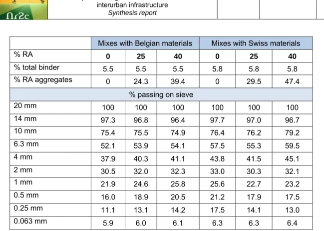
Table C.1.2 shows the final mix gradings for the various variants. The percentage of RA given in table C.1.2 stands for the percentage of old binder (from RA) on the total binder content.
Type Pen [1/10mm] R & B [°C] Binder content [%]
Belgian RA 17 67.3 5.5
03-EPFL
Page 7 of 65
Contract TST3-CT-2003-505831 Authors: N. Bueche, J. Dumoulin, T.
Sedran, J.-P. Marchand, D. Kokot, B. Kalman et al.
File : Deliverable2.2 Synthesis report-Rev5.doc
Table C.1.2: Grading of the different mixtures
C.1.2 Laboratory performance of the mixes
An extensive laboratory study was then performed on all mixtures to check the laboratory performances:
• Stiffness modulus was determined according to EN12697-26 annex A (two-point bending test on trapezoidal samples) for temperatures between -20 °C and 30 °C and for frequencies between 1 and 30 Hz.
• Resistance to fatigue of the different mixes was determined according to the BRRC-method [4] (two point bending test on trapezoidal samples) at 15 °C and 10 Hz. This test method is close to EN12697-24 annex A, but is stress controlled and performed on large samples.
• Resistance to permanent deformation is determined according to EN12697-22 (large device in air) at a temperature of 50 °C.
• Water sensitivity is determined as the indirect tensile strength according to EN12697-23 before and after conditioning in water according to EN12697-12.
The results are given in table C.1.3. We note that for the Swiss mixtures with RA, some of the tests were performed with a lower binder content (5.7 and 5.6 % for 25 % and 40 % of RA respectively, instead of 5.8 %). The reason for this is that in an asphalt plant, the variations on binder content of RA are usually larger than in the laboratory. With a high percentage of re-use, the impact of this parameter on the total binder content is important. A way to deal with this uncertainty in the phase of mechanical performance testing is to make the tests with the most unfavourable estimation of the binder content. For the mix with 40 % of RA, a variation of 0.5 % on the binder content of the RA would lead to a variation of 0.2 % on the total binder content. By doing some tests with a total binder content of 5.6 % instead of 5.8 %, the laboratory tests will be on the safe side.
Mixes with Belgian materials Mixes with Swiss materials
% RA 0 25 40 0 25 40 % total binder 5.5 5.5 5.5 5.8 5.8 5.8 % RA aggregates 0 24.3 39.4 0 29.5 47.4 % passing on sieve 20 mm 100 100 100 100 100 100 14 mm 97.3 96.8 96.4 97.7 97.0 96.7 10 mm 75.4 75.5 74.9 76.4 76.2 79.2 6.3 mm 52.1 53.9 54.1 57.5 55.3 59.5 4 mm 37.9 40.3 41.1 43.8 41.5 45.1 2 mm 30.5 32.0 32.3 33.0 30.3 32.1 1 mm 21.9 24.6 25.8 25.6 22.7 23.2 0.5 mm 16.0 18.9 20.5 21.2 17.9 17.5 0.25 mm 11.1 13.1 14.2 17.5 14.1 13.0 0.063 mm 5.9 6.0 6.1 6.3 6.3 6.4
03-EPFL
Page 8 of 65
Contract TST3-CT-2003-505831 Authors: N. Bueche, J. Dumoulin, T.
Sedran, J.-P. Marchand, D. Kokot, B. Kalman et al.
File : Deliverable2.2 Synthesis report-Rev5.doc
(*) determined for 5.7 % binder content instead of 5.8 % to investigate the risk of durability loss (**) determined for 5.6 % binder content instead of 5.8 % to investigate the risk of durability loss
Table C.1.3: Laboratory performance of the different variants
It was concluded that a high laboratory performance was reached on all aspects:
• All mixes have a very high stiffness around 12'000 – 13'000 MPa at 15 °C and 10 Hz.
• The resistance to permanent deformation is very high: always below 5 %. Note that this is the lowest value (best performance) according to the European specifications in EN1308-1.
• The resistance to the action of water is very high: for all mixes above 90 %, which shows that durability problems are not to be expected.
• The resistance to fatigue is very high: above 1.0 x 10⁶ cycles at 120 microstrain. This is at least a
factor seven better than a conventional Belgian mix for underlayers.
• The void content (measured hydrostatically) of the Swiss mixes with 25 % (binder content 5.7 %) and 40 % RA (binder content 5.6 %) is rather high: 5 % respectively 6 %.
• Mixes with reclaimed asphalt have equivalent performance as mixes without RA.
C.1.3 Accelerated loading tests
The accelerated loading tests have been performed in LAVOC's facility. Using this facility, the different mixtures have been tested in an accelerated way by controlling different parameters. In addition to the ALT, some other tests on in situ mixes have been performed with the aim of providing additional information for a better performance analysis.
C.1.3.1 Accelerated loading tests setup
The selected solutions were tested in full-scale accelerated loading testing (ALT) facility of LAVOC. They have been applied in a test section which dimensions are 13.1 m x 5.4 m (circulation direction). The pavement design has been carried out using two specific pavement design softwares based on the multilayer theory of Burmister: the Belgian software DimMET (developed by BRRC and Febelcem for the Walloon Ministry of Equipment and Transport) and a French design method with the help of the
Mixes with Belgian materials Mixes with Swiss materials
% RA 0 25 40 0 25 40 % total binder 5.5 5.5 5.5 5.8 5.8 5.8 % voids gyratory (100 gyr.) 3.3 3.8 2.7 3.3 3.2 1.8 Rut depth [%] at 30'000 cycles, 50 °C 2.7 - - 3.0 2.5 2.8 ITS-testing Voids [%] (hydrostatic) Strength before [MPa] ITS-ratio 3.3 2.5 98 % 2.8 2.3 95 % 2.4 2.4 101% 3.7 2.3 92 % 5.0 (*) 1.5 (*) 104%(*) 6.0 (**) 1.3(**) 94 %(**) Stiffness modulus [MPa] at 15 °C - 10 Hz 12740 - 12830 13900 12460 (*) 12050 Fatigue [15 °C, 10 Hz] Slope a ε6 (μstrain) N for ε = 120 μstrain 0.156 123.4 1.2 X 10⁶ - - 0.146 120.1 1.0 X 10⁶ 0.097 143.2 6.2 X 10⁶ - - - 0.131 123.7 1.3 X 10⁶
03-EPFL
Page 9 of 65
Contract TST3-CT-2003-505831 Authors: N. Bueche, J. Dumoulin, T.
Sedran, J.-P. Marchand, D. Kokot, B. Kalman et al.
File : Deliverable2.2 Synthesis report-Rev5.doc
NOAH software. For this pavement design, the aim was to have a structure which is expected to reach the end of its design life after 2/3 of the planned passages. More details can be found in [5].
The tested structure, represented in figure C.1.1, is as follows:
• Layer 1: AC MR8 (3 cm),
• Layer 2: High Modulus Asphalt (8 cm),
• Layer 3: Soil foundation composed by gravel 0/60 (40 cm), fine sand (145 cm) and concrete.
Four different sections have been studied, with various HMA contents: a reference without RA (field 0), a section with 25 % of RA (field 1) and two sections with 40 % of RA of which one doesn’t include a wearing course (field 3).
Figure C.1.1: Cross section view of the tested pavement
The sections have then been loaded with a heavy traffic simulator (axle load of 12 tons, tyre pressure of 0.8 MPa and super-single tyre), which simulates traffic close to in situ conditions. In order to tests the different pavement types, three positions of circulation have been defined (figure C.1.2):
• Position A: Two wheels on field 3 with 40 % RA, no top layer (axles A1 and A2)
• Position B: One wheel on field 2 with 40 % RA (axle B1) and one wheel on reference field 0 (axle C1)
• Position C: One wheel on the reference field (axle C2) and one wheel on the field 1 with 25 % RA (axle D1)
Figure C.1.2: Positions of circulation for ALT testing
40 % RA 0 % RA 25 % RA
Field2 Field0 Field1
Field3 Fine sand Gravel Fine sa nd
position A position B position C
03-EPFL
Page 10 of 65
Contract TST3-CT-2003-505831 Authors: N. Bueche, J. Dumoulin, T.
Sedran, J.-P. Marchand, D. Kokot, B. Kalman et al.
File : Deliverable2.2 Synthesis report-Rev5.doc
In order to measure horizontal stress and strain as well as temperature, different sensors have been installed at the bottom of the HMA and also at the interface between HMA and top layer. For temperature measurements, classical Pt100 have been used. Deformation measurements have been achieved using KYOWA strain gauges. A total number of 57 sensors have been installed in the pavement.
In addition to these sensors, surface deflection has been measured using a specific deflection beam instrumented with LVDT sensors (Figure C.1.3). Using this device, measurements close to the wheel passage have been performed.
Figure C.1.3: Specific deflection beam used in the ALT facility
The behaviour of the different sections has been assessed through two following test phases:
• In a first part, fatigue tests have been performed at a constant air temperature of 15 °C. During these fatigue tests, about 100'000 wheel passages have been performed on each position except position A that has got a total of 190'000 fatigue passages.
• The fatigue tests have then been followed by low temperature tests (LT). The aim of the second test phase was to simulate temperature cycles with circulation as well. Hence, air temperature variations between 2 °C and -7 °C were applied during 12 day for each position of circulation. In order to have a good temperature control, an isolated cabin with a cooling system using ventilators has been applied.
C.1.3.2 Results and analysis of the ALT
A total of more than 370 measurements have been performed during the whole test duration. For an assessment of the fatigue resistance of the different mixtures, special emphasis has been put on the deformations at the bottom of the asphalt layer. Traction is effectively most important at the bottom of the HMA and fatigue cracking will most likely occur at this interface [6].
Different comparisons between the mixtures have been carried out with the aim to assess if there is any negative effect using mixes with a high percentage of reclaimed asphalt instead of a mixture without RA. Parts of the results and the conclusions are presented hereafter, more details can be found in [7].
Comparison between 25 % RA and 0 % RA
In following figure C.1.4, each gauge is represented by a line while the code indicates the measurement axle C2 (0 % RA) or D1 (25 % RA). The first 100.000 passages correspond to the fatigue tests at 15 °C while the passages performed between 100.000 and 210.000 correspond to the low temperature tests (LT).
It is obvious that the general trend is the same for both axles i.e. both mixes. The small differences observed are not significant enough for concluding to a much better behaviour of the section with 25 % RA, but show that its resistance is at least the same as that of the reference mix. Moreover, the general order of magnitude for the deformation decreases during the low temperature tests. This was expected because by reducing the temperature, the pavement becomes stiffer and consequently the deformation decreases.
03-EPFL
Page 11 of 65
Contract TST3-CT-2003-505831 Authors: N. Bueche, J. Dumoulin, T.
Sedran, J.-P. Marchand, D. Kokot, B. Kalman et al.
File : Deliverable2.2 Synthesis report-Rev5.doc
Figure C.1.4: Comparison between the performance of axle C2 (0 % RA) and D1 (25 % RA) Comparison between 40 % RA and 0 % RA
The same comparison has been carried out for the mixtures with 40 % RA (axle B1) and the reference mix without recycling material (axle C1).
In figure C.1.5 below, the general trend shows a decreasing of the deformation during low temperature tests (between 100.000 and 190.000 passages) that was expected, but the order of magnitude is slightly bigger than for previous comparison with deformation up to 300 με. Comparing both mixes, the measurements on the section with the reference mix are a bit lower than with the mix containing 40 % recycling material. However, the differences measured are very small and they cannot be considered as a conclusion about a major behaviour difference between the mixes.
0.00 100.00 200.00 300.00 400.00 500.00 600.00 700.00 De fo rm at io n [1 0 ‐6] Passages [‐] ‐11‐B1‐01‐LG ‐11‐B1‐02‐JL ‐11‐B1‐03‐LG ‐11‐B1‐05‐LG ‐11‐C1‐01‐LG ‐11‐C1‐02‐JL ‐11‐C1‐03‐LG ‐11‐C1‐05‐LG
Figure C.1.5: Comparison between the performance of axle C1 (0 % RA) and B1 (40 % RA)
Considering both comparisons above between the different mixes, we can conclude that the same order of magnitude has been measured for the deformation in the mixes without and with RA. The
03-EPFL
Page 12 of 65
Contract TST3-CT-2003-505831 Authors: N. Bueche, J. Dumoulin, T.
Sedran, J.-P. Marchand, D. Kokot, B. Kalman et al.
File : Deliverable2.2 Synthesis report-Rev5.doc
general trend of slightly lower deformation in the section with 25 % RA is not sufficient enough in order to deduce a difference in fatigue resistance.
In addition to the different measurements, some calculations have been performed using the NOAH software. These calculations have been carried out at the end of the tests with the aim of providing some additional information about the different material behaviour and an assessment of the difference between calculations and measurements. Moreover, this has been used in order to assess the quality of the measurements in comparison with theoretical values.
For this part of the study, updated values obtained through laboratory tests have been considered in order to have accurate material characteristics. In fact, a few points with stabilized temperature have been chosen and the calculation compared with the measurements for these selected points, considering the elastic modulus in function of the layer's temperature registered.
The outputs of these calculations were very interesting and quite good correlations with measurements have been found. In some cases, less than 15 % difference has been calculated. Considering all the input parameters that influence the calculation (in situ material not necessary the same as laboratory samples, consideration of fatigue effect, Burmister theory, ..) the results obtained are in good agreement with the measurements. Moreover, the additional calculation permitted to make a sensitivity analysis on the bonding conditions and the effect of the top layer, as well.
Figure C.1.6 gives an example of the calculation results. In this figure, the calculated points are represented with red dots.
0.00 100.00 200.00 300.00 400.00 500.00 600.00 700.00 0 20'000 40'000 60'000 80'000 100'000 120'000 140'000 160'000 180'000 200'000 De fo rm at io n [1 0 ‐6] Passages [‐] ‐11‐B1‐01‐LG ‐11‐B1‐02‐JL ‐11‐B1‐03‐LG ‐11‐B1‐05‐LG Calculated points
Figure C.1.6: Comparison between calculated and measured deformations for axle B1 (40 % RA)
We can conclude from the ALT study and additional calculations that no negative effect of a high percentage of RA has been observed. Indeed, the mixes with RA showed at least equal performance as the mix without recycling material. Moreover, the tests conducted reached a performance rate and load repetition that is high enough for concluding that the behaviour of the mixes is very good.
C.1.4 Other tests related to ALT
In addition to the ALT, additional tests and analysis have been performed on in situ mixes. They are discussed hereafter. More details can be found in [7].
Wheel tracking tests
Wheel tracking tests have been conducted on laboratory mixes during the mix design. In order to assess the resistance to rutting of the in situ mixes that have been tested through ALT, different slabs have been constructed during the laying phase. These slabs have then been tested at 50 °C according to the EN 12697-22. Moreover, the rutting resistance under severe conditions have also
03-EPFL
Page 13 of 65
Contract TST3-CT-2003-505831 Authors: N. Bueche, J. Dumoulin, T.
Sedran, J.-P. Marchand, D. Kokot, B. Kalman et al.
File : Deliverable2.2 Synthesis report-Rev5.doc
been assessed through a test at 60 °C. Indeed a test with extreme temperature has been found relevant as it would be possible to have HMA base layers that could reach very high temperature in some southern European countries, for instance.
The tests results showed very good performance regarding rutting for all mixes. Indeed, the proportional rut depth at 30’000 cycles was always under the limit of 5 % which corresponds to the best category for the future European method at 50 °C (EN 1208-1).
The tests at 60 °C permitted to confirm the very good resistance of the different materials regarding rutting, even with severe conditions. Indeed proportional rut depths close to 5 % have been measured.
Tests on cores
Different coring campaigns were carried out during the tests at the ALT facility: before the beginning of the tests, after the fatigue tests and at the end of the low temperature tests, as well. At each stage, cores have been taken in undisturbed areas and/or in wheel path, this in order to further analyse the effect of the load and temperature on the pavement characteristics.
The maximum densities of the test sections did not change during the ALT study. The section with 40 % RA had 20 kg/m3 less maximum density compared to the laboratory mix with the same content
of RA. The difference is probably due to the larger variability of RA compared to clean aggregate. The maximum densities for the other test sections matched the densities of the laboratory mixes.
The bulk densities were used to calculate the air void content. In the sections with 0% and 40% RA, the air void content were approximately 2.5%, although the measurements indicated that the air void content was approximately 1% higher initially. This recorded decrease could be the result of compaction by the loading tests done, but this conclusion is contradicted by the tests done on drilled cores outside the wheel path after the ALT and low temperature tests had been finalized. These cores had the same air void content as the ones in the wheel path after the ALT. For the section with 25% RA, the air void content was approximately 5%, which is higher than what was recorded in the laboratory studies. Also for this section there is an indication that the air void content was initially higher.
The water sensitivity as measured by the indirect tensile strength ratio, did not change during the course of the ALT. It remained close to 90% for all test sections during the accelerated tests, which is similar to the values recorded for the laboratory mixes.
The stiffness modulus measured at four temperatures did not appear to change during the accelerated loading tests done on the test sections.
Master curves of stiffness moduli were recorded and described by the equation:
(
)
h r f E E ) 5 . 0 Exp( 1 max − −= , which has only two parameters, the limiting stiffness modulus, Emax, and the factor h. The repeatability limits for these factors for a mean of three samples were determined to be 10% and 0.16, respectively. There were no recorded change above the repeatability limits for Emax, or h during the course of the ALT study for the three test sections. The master curves for the tests sections with 0% and 40% RA were also almost identical to the master curves recorded for the laboratory mixes with the same compositions.
03-EPFL
Page 14 of 65
Contract TST3-CT-2003-505831 Authors: N. Bueche, J. Dumoulin, T.
Sedran, J.-P. Marchand, D. Kokot, B. Kalman et al.
File : Deliverable2.2 Synthesis report-Rev5.doc -6 -4 -2 2 4 6 5000 10000 15000 20000 25000
Figure C1.7: An example of the master curve of the stiffness modulus and the best of the equation
used to parameterize the master curve.
Binder analysis
Making a study with reclaimed asphalt, the behaviour of the binder and especially the mix of old and new binder are also important. In order to assess these parameters, a specific study of the binders was carried out and different conditions selected:
• Raw binder with and without ageing
• Binder recovered from RA
• Binder laboratory mixes and ageing using RTFOT
• Binder recovered from in situ mixes
• Binder recovered from laboratory mixes.
Classical tests (pen, R&B) have been performed for each binder condition but also rheological tests like DSR. This analysis showed that the different laboratory and in situ mixes are consistent as rather comparable values have been found. This study also demonstrated that RTFOT ageing corresponds rather well with laboratory production ageing whereas field ageing seemed to be more severe. This can be linked with the high production temperatures.
Tests on big slabs
A specific test in controlled conditions has been performed on big slabs taken in the ALT facility. While the tests in the ALT facility focused on fatigue testing at 15 °C and low temperature tests, it has been decided to investigate the mix behaviour at elevated temperatures. Hence, three large slabs were extracted from undisturbed areas and sent to DRI for testing in the Danish Asphalt Rut Tester (DART). These devices permitted to simulate a rolling load with side wander random normally distributed [7]. For the tests in DART on big slabs, a standard testing has been conducted with 50 kN wheel load and 110.000 load applications. The results have then been compared with the results obtained on Danish motorway pavements. After first tests according to the standard procedure, a further 44.000 loads were applied at an elevated temperature of 50 °C surface temperature / 40 °C bottom temperature, this in order to be sure to reach rutting and analyze the limits of the material, as well. The permanent deformation evolutions for the three slabs are illustrated in figure C.1.8:
03-EPFL
Page 15 of 65
Contract TST3-CT-2003-505831 Authors: N. Bueche, J. Dumoulin, T.
Sedran, J.-P. Marchand, D. Kokot, B. Kalman et al.
File : Deliverable2.2 Synthesis report-Rev5.doc
Figure C.1.8: Rutting behaviour for the three tested slabs
As the deformation obtained during the first 20'000 loads will to some extent mainly depend on initial compaction under the wheel load, it cannot be concluded from these data that rutting of the slab with 40 % RA is much less pronounced than for the other two slabs. For a comparison of rutting behaviour of different slabs without this initial disturbance, the increase of rutting from 20'000 to 40'000 loads is calculated. For the different slabs, we obtained a rutting increasing between 0.25 mm (25 % RA) and 0.32 mm (0 % RA). Comparing these results with the Danish standards on highways (between 0.5 and 5 mm), we conclude that rutting susceptibility is much better than for standard motorway pavements. Moreover, no significant difference between the different slabs can be determined. Concerning elevated temperature tests, the slab with 40 % RA had a slightly but not significantly faster rutting development than the slab with 25 % RA.
C.1.5 Conclusions and recommendations
In this innovation, a sophisticated methodology has been used, based on a mix design software, different laboratory performance tests and also ALT testing. Hence, a lot of performance characteristics under several circumstances have been investigated through these tests, to obtain as much as possible information about the performances of the different mixes.
High performance mixtures were obtained with equivalent performance for mixes with RA than mixes without RA, provided that an optimization of the mix design was performed based on the analytical mix design study and on the results of the performance tests. Three designed mixtures were further tested in the ALT-testing facility of LAVOC. No failure was observed in these experiments, and mixes with RA showed equivalent performance as mixes without RA. It was shown that the use of high percentage of reclaimed asphalt in base layers has no negative effect on the laboratory mix performance. ALT, wheel tracking tests, tests in DART and also laboratory tests on cores and binders samples came to the same conclusion that no negative effect of a high percentage of RA could be identified so far. However, it is important to keep in mind that such a conclusion cannot be extended to all the HMA mixes. Some parameters like the grading curve, recycling material and binder type play a key role in the final properties. Considering these elements, it is recommended to put special attention on the characterisation of the reclaimed asphalt, on the mix design and on the laboratory tests, in order to fully guarantee performance.
According to the results obtained and the good results with the different mixes, it is advisable to make some in situ tests that would permit to validate the results of this research. Another important question is where to put the efficient limit concerning the RA content. Obviously, the encouraging results obtained allow us to think about 50 % or 60 % recycling material. However, further increase of RA content will necessitate a very good control of some parameters such as viscosity may require the use of new techniques as well.
0,00 1,00 2,00 3,00 4,00 5,00 6,00 7,00 8,00 0 20.000 40.000 60.000 80.000 100.000 120.000 140.000 160.000 180.000 Loads Pe rm an en t d e fo rm at io n [ m m ] 0 % RA 25 % RA 40 % RA
03-EPFL
Page 16 of 65
Contract TST3-CT-2003-505831 Authors: N. Bueche, J. Dumoulin, T.
Sedran, J.-P. Marchand, D. Kokot, B. Kalman et al.
File : Deliverable2.2 Synthesis report-Rev5.doc
C.2 Innovation 2.1B: Crack-free semi-rigid pavement incorporating two
industrials by-products
C.2.1 General scope of the innovation
In semi-rigid pavement structures, the well graded treated aggregate used as a base course always present transversal cracks because:
- it is submitted to different shrinkages: desiccation in the first months and thermal shrinkage during its all life;
- its shrinkage is restrained by the sub-base
- it’s a rigid material, with an elastic modulus generally higher than 20 GPa.
Due to the traffic and the weathering, the longitudinal cracks inevitably reflect themselves in the wearing course. When the cracks are wide-opened, the interlocking of the pavement blocks on the both sides of the cracks is limited and then the structural efficiency of the pavement is lessened. Moreover, these cracks damage the aesthetic, the evenness and the comfort of the wearing course. They finally facilitate the penetration of water, which accelerates the ageing of the structure.
That is why regular maintenance (cracks silting up) is generally needed, approximately each 3 years. Yet, although it is efficient on the structural point of view, it does not solve the aesthetic and evenness matters. Moreover, maintenance works disturb the road users and represent an important cost. So cracking appears less and less acceptable by the construction financing authorities and different strategies were developed to avoid its appearance:
- pre-cracking system in the construction phase. Thanks these techniques, it is possible to control the position of the cracks, then to limit the space between two cracks (around 2 meters) and consequently the thickness of the cracks;
- interface anti-cracking systems which try to block the cracks under the wearing course;
Unfortunately, the efficiency at long term of these techniques is not completely demonstrated and generate extra-cost at construction.
In conclusion, well graded aggregate is a durable material but its cracking tendency limits the life duration of semi-rigid pavement structure. So it would be interesting to develop crack free well-graded treated aggregate to obtain long life semi rigid pavement with low maintenance cost. The scope of this innovation is to evaluate the feasibility of such a material thanks the use of two by-products.
The idea is the following:
- some by-products like steel slag display spontaneous swelling behaviour and release lime; - pozzolans like fly ashes react with lime to give hydrates (CSH) and mechanical properties;
- optimized mixtures of such swelling by-products with inert materials and pozzolans could present structural properties in combination with a controlled swelling, which could overcome the thermal shrinkage.
If such mixtures could be realized, they would allow:
- construction cost savings (as a part of the components are by-products);
- maintenance cost savings (no cracks means thinner structure and no joint maintenance); - high quality materials savings (by the use of by-products).
These goals are in perfect accordance with the main objectives of the Innovation task which are low cost pavement construction and maintenance techniques.
C.2.2 Bibliographical search
During the production of iron and steel, the iron oxides and some of the metal oxides are reduced forming the metal melt. The remaining oxides will be bound into an oxide melt: the slag. The production of iron and steel is normally carried out as a series of discrete operations with essentially: the reduction in the blast furnace, the steel process using the Basic Oxygen Furnace (BOF) and
03-EPFL
Page 17 of 65
Contract TST3-CT-2003-505831 Authors: N. Bueche, J. Dumoulin, T.
Sedran, J.-P. Marchand, D. Kokot, B. Kalman et al.
File : Deliverable2.2 Synthesis report-Rev5.doc
Electric Arc Furnace (EAF) process following by the finishing of liquid steel in the secondary metallurgical treatment.
The pig iron production in the blast furnace leads to the blast furnace slag, which properties can be influenced by the cooling conditions: air cooling generates the crystalline air cooled blast furnace slag (ABFS) and rapid cooling with water or even with air generates the glassy granulated blast furnace slag (GBS). Both produce about 250-300 kg per ton of pig iron made (the European pig iron production are more than 60 million tons in 2005), they are fully used respectively as aggregate in road construction or concrete, and as cement compound or as addition to concrete.
Steel slag is produced from the further refining of iron in a Basic Oxygen Furnace (BOF Slag) or from melting recycled scrap in an Electric Arc Furnace (EAF slag). Both produce about 100 kg per ton of steel made and in Europe every year nearly 12 million tons of steel slags are produced. Owing to the intensive research work during the last 30 years, about 65% of the produced steel slags are used on qualified fields of application, today. But the remaining 35% of these slags are still dumped. In France, the dumping rate of steel slags is close to 25 %, for an annual production close to 1.7 million tons (in 2005).
Owing to their physical, chemical and mineralogical properties, the steelmaking slags are suitable for various kinds of applications in industrial areas. EAF slag is basically used in road construction (as layer with or without binder) and earthworks (road cover, road base, way's consolidation) and their high resistance to wear successfully promoted their use as mineral aggregates for wearing course in road surfaces. BOF slag has been previously used in the blast furnace to recover the iron in the slag and as lime carrier. Due to the extent requirements on the phosphorous content of steel, BOF slag recycling became more and more restricted and new applications had to be found. BOF slags are used in road construction, as aggregate for concrete or for hydraulic engineering, as fertilizer in agriculture, as pollutant removing filter or soil stabilization.
The BOF- and EAF-slags from different sources within Europe, are generally comparable and independent of their producers. Differences arise from the use of dolomite rather than lime as fluxes with the effect of a higher MgO-content in the slag. BOF- and EAF-slags are calciumsilicatic with a range of CaO between 42 and 55%, and a range of SiO2 between 12 and 18%. EAF-slags comprise CaO between 25 and 40% and 12 to 17% SiO2. Their MgO-content may be higher due to the reactions with the refractory lining. The main mineral phases of BOF- and EAF-slags are dicalciumsilicate, dicalciumferrite and wustite. The content of free lime and free MgO is the most important component for the utilisation of steel slags for civil engineering purposes, with regard to their volume stability. In contact with water, these mineral phases will react to hydroxides. Depending on the rate of free lime and/or free MgO hydration, it causes a volume increase of the slag mostly combined with a disintegration of the slag pieces and a loss of strength. So, the volume stability is a key criterion for using steel slags as a construction material.
Then, for many steelworks, a significant proportion of this slag will be landfilled, and of the materials dumped, it will often form the largest proportion. With increasing pressure in many countries for greater use of secondary aggregates to preserve the natural resources, steels slags offer a promising and relative abundant alternative. During the last twenty years, the problem of volume stability was the main objective of the research work on steel slag in Europe. Today, this problem can be avoided with a suitable weathering of the slag in order to favour the free lime hydration. Such slag can then be safely treated with bituminous binder for road wearing course notably. Moreover, steelmaking slags can be used at all levels (unbound in the lower layers, bituminous-bound in the upper courses, and as a surface dressing) (Piret et al., 1982). Yet the slag maturation still remains problematic because of the associated handling or the pressure imposed by the environmental policies. This is why, it is today necessary to promote a new approach for the valorisation of steel slag in civil engineering, considering slags of lower quality and trying to convert slag disadvantages into positive aspects.
The combination of BOF slag (with or without weathering) with other materials is another way to limit the volume instability. Numerous studies dealing with the composition of mixes of BOF slag aggregates with other materials, such as granulated blastfurnace slag, municipal solid waste incinerator bottom ash, fly ash, used for road construction can be found in the literature. For example, by mixing 70-85 % of weathered BOF slag with 15-30 % of granulated blastfurnace slag, a road base
03-EPFL
Page 18 of 65
Contract TST3-CT-2003-505831 Authors: N. Bueche, J. Dumoulin, T.
Sedran, J.-P. Marchand, D. Kokot, B. Kalman et al.
File : Deliverable2.2 Synthesis report-Rev5.doc
was produced without significant expansion damage. Moreover, a slowly setting composition is obtained which provides, at low cost, a quality road base which can be considered as semi-rigid in comparison with concrete bases (Piret et al., 1982). Best (1987) developed a well graded composite similar to the French 'graves-laitier', but containing both air-cooled blast furnace slag (5-20 mm, 57 vol.%), LD slag (0-5 mm, 28 vol.%) and quenched blast furnace slag (15 vol.%). The cementitious action of the quenched blast furnace slag, activated by the free lime embedded in the BOF slag binds the mix. Such a pozzolanic reaction consumes the free lime non-expansively, lowering the tendency of the aggregate for expansion. This new material referred to as "self-binding slag composites" presents the advantage to minimise the need of chemical activators owing to the free lime present in the slag. Juckes (1991) confirmed that the dilution of the BOF slag and the associated cementitious reaction lead to a limited expansion of such mixes, arguing in favour of an absorption of the expansion attributed to the BOF slag aggregate by the semi-rigid environment. This was recently shown again in a recent study made by Tikkakoski et al., (2005).
In these previous studies, the mix optimization was carried out in the laboratory by seeking the best geotechnical performances. It was assessed by classical techniques used in road engineering such as measurement of compressive strength, Proctor optimum, CBR, freeze-and-thaw and rutting resistance or volumetric stability. However, from a practical point of view, the use of BOF slag aggregates in road construction remains unusual because of the uncertainties about volume stability. In fact, this volume stability depends on numerous factors such as proportions of the different components, free lime content of BOF slag, residual potential volume increase after weathering. So, whereas such a technique of combination with other granular materials offers a promising way of valorisation for BOF slags in road, it requires more technical specifications and needs development of tools to be able to predict and ensure the volume stability of the obtained mixes.
In that context, Deneele et al. (2005) have proposed a new method to predict the swelling of any combination of swelling aggregate and inert aggregate fractions. This method is based upon the Compressible Packing Model developed at LCPC which was implemented in the software René-LCPC (Sedran and de Larrard 1995, Sedran and de Larrard 1996, Sedran 1999, de Larrard 1999). This software was first developed for the optimization of concrete, but the framework of the model is much more general and can be used for other types of granular packing or granular suspensions. The software needs three types of data for each granular component: the dimensions of the particles (as given by the grading curve), the specific gravity and the packing density. It then predicts, for any combination of the fractions, either the compaction index from the packing density, or the packing density from the compaction index. This latter parameter is a characteristic of the placing method tabulated thanks calibrations (for example, 9 for packing under vibration and 20 kPa pressure). The software was widely validated in the field of the packing density of dry granular mixtures and gives an error lower than 1% in absolute value, in comparison with the experiments.
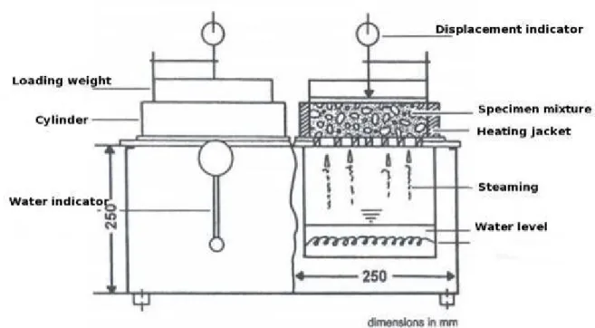
The authors have verified that the weathering of compacted BOF slag samples in an accelerated test with a steam apparatus (see below) induces swelling and grading changes of the material. The grading change can be directly evaluated by sieving, and swelling can be interpreted as a difference in packing density of the mix before and after weathering. In fact, swelling S% can be expressed as following:
⎟⎟
⎠
⎞
⎜⎜
⎝
⎛
−
ρ
ρ
=
−
=
1
C
C
100
V
V
V
100
S
f f i i i i f Where:- Vi and Vf are respectively the volume of the sample before and after weathering
- Ci and Cf are respectively the packing density of the sample before and after weathering
- ρi and ρf are respectively the specific gravity of the BOF before and after weathering
Deneele et al. (2005) have then introduced the properties of the different classes of grains of BOF slag into Rene-LCPC for two cases: before and after weathering. From these data, they were able to calculate the packing density before and after weathering of several mixes made of BOF slag and Air-cooled Blastfurnace slag on one hand and BOF slag aggregates and limestone on the other hand. They were then able to calculate a theoretical swelling according to the previous equation. These
03-EPFL
Page 19 of 65
Contract TST3-CT-2003-505831 Authors: N. Bueche, J. Dumoulin, T.
Sedran, J.-P. Marchand, D. Kokot, B. Kalman et al.
File : Deliverable2.2 Synthesis report-Rev5.doc
results confirmed to be in good agreement with the experimental data for mixes containing less than 50% of BOF slag. For higher content of BOF slag, the theoretical swelling was overestimated. According to the authors, this is due to the fact that for high volume of BOF slag, the mixes were less porous so that, during the accelerated swelling test, the steam could not penetrate into the packing and then the experimental swelling was lower than could be expected.
Using the approach proposed in that study, it is then possible to optimize the mix composition of BOF slag with inert aggregate, in order to have an acceptable and limited swelling.
Finally, combining a BOF slag with a fly ash and an inert aggregate could be a good way to obtain a well-graded aggregate with noticeable mechanical properties and a controlled swelling. In fact the fly ash may react as a pozzolan with the lime released from the BOF-slag and the swelling could be controlled by the introduction of an inert aggregate thanks the use of Rene-LCPC.
C.2.3 Preliminary feasabily tests
Materials selected for this study were:
• a 0-10 mm fresh Basic Oxygen Furnace slag (the same as presented in Deneele et al. (2005) ) representative of French production
• a 0/6 mm and a 10/20mm "Le Boulonnais" limestone • coal fly ashes from Surchiste company
• a quicklime (activator)
A first step is to rapidly identify promising well graded aggregate mixtures producing at the same time some swelling to counteract the effect of the different shrinkages, and noticeable mechanical performances. Both are needed to produce a road layer with bearing capacity and no cracks.
In case of success, the selected mixtures should be tested in the same way but at 20°C and at longer term. In fact, 20°C is more representative of the temperature during the road life, moreover the temperature has a great influence on the chemical reactions involved: expansion of free lime, pozzolanic reaction between lime and fly ash. So the evolution of swelling compared to that of the elastic modulus and tensile strength may change in great proportions compared to tests at 90°C. In a first approximation we will aim at a splitting tensile strength between 0,5 to 1 MPa which corresponds to GC1 or GC2 class of cement treated well graded aggregate in EN 14227. A rough calculation of swelling to be aimed at, can be made with the following assumptions:
- the well-graded aggregate have a long term splitting strength of 1 MPa and an elastic modulus of 20 000 MPa;
- the well-graded aggregate has a thermal expansion coefficient around 10-6/°C, and the layer may be submitted to a maximum temperature variation in a range of 30°C (between night and day and summer and winter). This lead to a maximum 300 10-6 shrinkage between hot period and cold one;
- autogeneous shrinkage of the well graded aggregate is negligible and its drying shrinkage is around 300 10-6.
The well graded aggregate is then submitted to a maximum 600 10-6 strain, yet the acceptable strain
at long term before cracking is 1/20000=50 10-6. So the swelling should be at least 250 10-6. In fact
this value is probably strongly underestimated because swelling may occur at young age while the well graded aggregate has a low value of elastic modulus. In that case strains generate few compressive strength to counteract the effect of thermal shrinkage which occurs during the all life of the road when the elastic modulus is higher. Moreover part of the benefit of the swelling may be lost with time due to relaxation in the material.
As explained before, the theoretical estimation of the mixes swelling is based on the difference in packing density between a fresh mix and the same mix after weathering, calculated with René–LCPC software. The calculation of these packing densities requires the preliminary following data for the different components:
- the grading curve; - the specific gravity; - the packing density.
03-EPFL
Page 20 of 65
Contract TST3-CT-2003-505831 Authors: N. Bueche, J. Dumoulin, T.
Sedran, J.-P. Marchand, D. Kokot, B. Kalman et al.
File : Deliverable2.2 Synthesis report-Rev5.doc
For the BOF slag, these properties were determined before and after weathering. As the other components were assumed to be inert, their characterization was made only without weathering. The effect of weathering on the slag particles is assumed to be dependant on their size. So, for a better characterization of the slag before and after weathering, its was first separated by sieving it in five fractions. Each fraction was then characterized individually. For particles coarser than 80µm, the weathering procedure was carried out according to the procedure in EN 1744-1, paragraph 19.3, but a modification was brought to the classical procedure since samples were subjected to a very slight compaction with the vibrating table. The steam test equipment available at LCPC is described in figure C.2.1. Another weathering procedure was applied to the finest aggregate class. In fact, when submitting the 0/0.08 mm fraction to the steam test, we observed a sudden raising of the slag sample and covering surcharge, which exceeded the height of the cylinder. Consequently, we have chosen to weather this finest fraction by immersion in water at 110°C (chamber temperature) during five days. The results are shown below.
Figure C.2.1: Principle of the steam apparatus: the sample is submitted to a steam flow while its
03-EPFL
Page 21 of 65
Contract TST3-CT-2003-505831 Authors: N. Bueche, J. Dumoulin, T.
Sedran, J.-P. Marchand, D. Kokot, B. Kalman et al.
File : Deliverable2.2 Synthesis report-Rev5.doc 0 10 20 30 40 50 60 70 80 90 100 1 10 100 1 000 10 000 100 000
D (µm)
P
a
ssin
g
(
%
)
Slag 0/10 before weathering Slag 0/10 after weathering Boulonnais 0/6 Boulonnais 10/20 Fly Ash
Figure C.2.2: Grading curves of the components
Specific gravity (kg/l) Packing densities Material Without weathering After weathering Without weathering After weathering Slag fraction 0/80µ 2.75 2.88 0.46 0.43 Slag fraction 80µ/315µ 2.76 2.88 0.444 0.392 Slag fraction 315µ/2mm 2.96 2.99 0.482 0.446 Slag fraction 2mm/6.3mm 3.06 3.11 0.551 0.533 Slag fraction 6.3mm/10mm 3.09 3.14 0.568 0.548 Limestone 0/6.3 mm 2.64 0.628 Limestone 10/20 mm 2.67 0.574 Fly Ash 2.16 0.601
Table C.2.1: Packing densities and specific gravity of the components
In conclusion, it can be observed that the weathering of slag mainly leads to: - a decrease of the packing density (mean value -7%);
- almost no change in the specific gravity (mean value +2,5%); - aggregation of small particles and splitting of coarse particles.
The measurements made on the BOF-slag have shown that they contain approximately a total of 10% of free lime and that only 50% of this lime can be hydrated. Moreover the European norm EN 14227-3 and the French one NF 98118 suggest for classical fly ash/lime well graded aggregate the following mean dosages:
- 10% of fly ash (between 8 to 12%)
- 1,7% of CaO (1,4 to 2,1) or 2,5% of Ca(OH)2 (2 to 3%)
These data lead to select a ratio of CaO/FA=0.17 in our mixes. When possible the CaO will be bring by the BO-slag. Which means a ratio BOF slag/ FA= 3.4.
René-LCPC software was used to generate different preliminary recipes (see Table C.2.2) with different theoretical swelling. Note that these swelling are probably overestimated here as the model
03-EPFL
Page 22 of 65
Contract TST3-CT-2003-505831 Authors: N. Bueche, J. Dumoulin, T.
Sedran, J.-P. Marchand, D. Kokot, B. Kalman et al.
File : Deliverable2.2 Synthesis report-Rev5.doc
was developed for packing without any hydraulic or pozzolanic reaction. In the present case, strength and so elastic modulus of the different mixes are expected to increase, thus restraining the swelling.
The assumptions of the calculations were the following:
- the packing index corresponding to the moulding of the sample is fixed 12. This value was fitted from the one obtained for packing at optimum proctor by Pouliot et al (2001).
- the calculations are made with no wall effect to be representative of free swelling of a huge sample of material.
In the first series (F1, F2, F3) we have:
- fixed the BOF-Slag/FA ratio to 3.4. By this way we have made the assumption that all the quick lime necessary for the fly ash was furnished by the slag;
- varied the BOF-Slag /limestone ratio to generate different swelling values. In a first time we have only selected the 10/20 limestone in order lessen the granular interaction with the slag particles. This theoretically allows moderate values of swelling even with high volume of slag ("the slag particles expand between the coarse inert particles with few effect on their packing arrangement). In the second series (F1, F4, F5) we have:
- the same BOF-Slag /limestone as in the first series to keep almost the same swelling level;
- imposed a content of 10% of fly ash to aim at higher theoretical mechanical properties (before swelling). In that case the quick lime furnished by the slag is not sufficient and we have to add directly a pat of it to maintain the CaO/FA ratio constant.
Mix Fly Ash (%) Lime stone 10/20 (%) Lime stone 0/6 (%) Steel slag 0-10 (%) Cao (%) Ca0/CV LD (% except 0-10 CV and Cao) Initial theoretical porosity Initial dry apparent density (kg/m3) Theoretical swelling (%) F1 10 56 0 34 0 0.17 37.8 0.1959 2162 2.63 F2 7 69.2 0 23.8 0 0.17 25.6 0.2455 2025 1.29 F3 4 82.4 0 13.6 0 0.17 14.2 0.3105 1846 0.60 F1 10 56 0 34 0 0.17 37.8 0.1959 2162 2.63 F4 10 66.4 0 23.1 0.5 0.17 25.8 0.2226 2070 1.30 F5 10 76.3 0 12.6 1.1 0.17 14.2 0.2634 1943 0.60
Table C.2.2: Theoretical swelling of different well graded aggregate calculated with Rene-LCPC
software
Table C.2.3 shows the mechanical performance obtained. After casting the cylinders were slowly heated to 80°C during one day, then cured at 80°C for 5 days and finally slowly refresh to 20°C during one day. The cylinders were preserved from desiccation during curing.
Mix Fly Ash (%) Lime stone 10/20 (%) Lime stone 0/6 (%) Steel slag 0-10 (%) CaO (%) (t/m3) ρdopm Wopm (%) Packing density Spliting tensile strength (Mpa) F1 10 56 0 34 0 2.23 7.5 0.829 0.16 F2 7 69.2 0 23.8 0 2.13 5.5 0.792 0.16 F3 4 82.4 0 13.6 0 2.02 3.5 0.754 0.19 F4 10 66.4 0 23.1 0.5 2.2 6.8 0.824 0.35 F5 10 76.3 0 12.6 1.1 2.16 6.2 0.819 0.49
03-EPFL
Page 23 of 65
Contract TST3-CT-2003-505831 Authors: N. Bueche, J. Dumoulin, T.
Sedran, J.-P. Marchand, D. Kokot, B. Kalman et al.
File : Deliverable2.2 Synthesis report-Rev5.doc
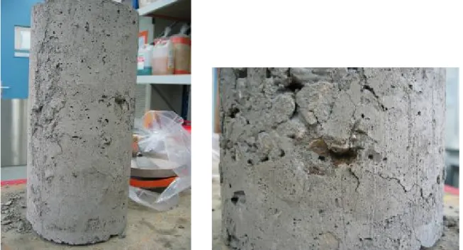
The results show that only limited performances in splitting tensile strength are reached with the mixes in the first series, where no quick lime is added. This can be explained in F1 by important swelling. The graphic C.2.3 shows that at the end of curing, cracks have appeared in the cylinders as well as brown zones which are typical of CaO hydration in the slag aggregates. In F3, the low performance is probably due to the low content of fly ash. Moreover, in that series, it is possible that even if pozzolanic reactivity is accelerated by the increase of curing temperature on one hand, the diffusion of the quick lime liberated from the slag aggregate is not accelerated on the other hand. The consequence may then be that the fly ash particles are not in contact with lime and that pozzolanic reaction does not occur much in the first week.
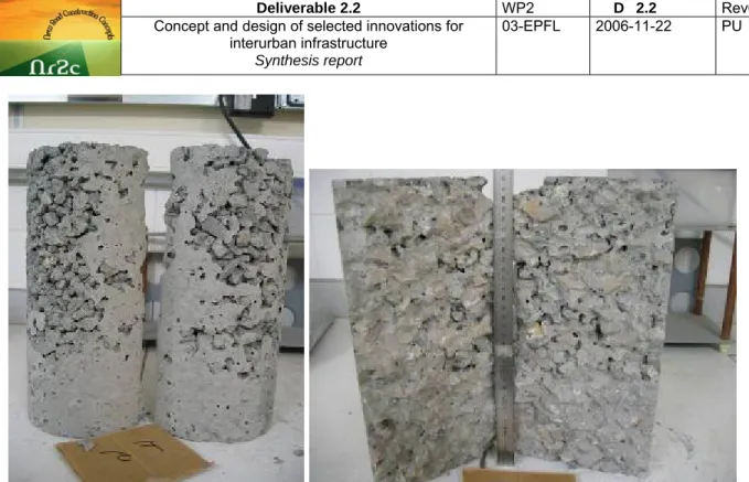
In the second series, F5 reach 0,5 MPa in tensile strength. This result is encouraging as theoretical swelling is around 6000 10-6. As it can be seen in figure C.2.4, no cracks was visible on the sample after curing.
Figure C.2.3: Pictures of the F1 mix after curing. Segregation is due to the gap graded skeleton.
03-EPFL
Page 24 of 65
Contract TST3-CT-2003-505831 Authors: N. Bueche, J. Dumoulin, T.
Sedran, J.-P. Marchand, D. Kokot, B. Kalman et al.
File : Deliverable2.2 Synthesis report-Rev5.doc
Figure C.2.4: Pictures of the F5 mix after curing. Segregation is due to the gap graded skeleton. No
cracks are visible.
In a first approach, we intended to use the steam machine presented in figure C.2.1 to make the swelling measurements in accelerated conditions. This apparatus allows a steam curing at 100°C and was already equipped with a displacement indicator. Yet after several trials it appears that the steam was not able to go through the sample because of the low porosity of the samples and that the displacement observed were due to a piston effect and not to swelling. Then a new way of measuring the swelling was tested
Using the procedure classically used for concrete samples, the idea is to include two steel inserts on in the two faces of a Ø16x 32 cm. The distance between these two inserts will then be measured at different ages with the measurement device presented in the figure C.2.5
Figure C.2.5: Tool realized for length measurement of Ø16x 32 cm of well graded aggregate. The
zero is made thanks an invar bar. The contact with the inserts of the sample or the bar is ensured by two steel balls.
03-EPFL
Page 25 of 65
Contract TST3-CT-2003-505831 Authors: N. Bueche, J. Dumoulin, T.
Sedran, J.-P. Marchand, D. Kokot, B. Kalman et al.
File : Deliverable2.2 Synthesis report-Rev5.doc
Compared to concrete we have here two main difficulties:
- samples are compacted and not cast. A new device must be design to be included in the mould of the VCEC compacting machine, to be able to put the insert in the samples;
- measurements have to be started at a young age, when the well grade aggregate has almost no tensile strength. So the anchorage of the insert has to be well studied.
The graphic C.2.6 describes the system developed to include the inserts during compaction: - a steel plate (9) is included in and empty millboard mould to which an insert (8) is screwed; - the well-graded aggregate is included in the mould;
- another steel plate (7) with an insert is put on the material; - the material is compacted with the piston (4).
Figure C.2.6: Principle adopted to include the insert while compacting
After several tests, the insert shown in figure C.2.7 was selected. It is made of stainless steel with a conic form with flat parts. This geometry allows a good filling of granular material near the insert, avoids movement and rotation of the insert at early age. A preliminary test has shown this new version of inserts is well anchored and allows a stable evaluation of the sample length.