Many-in-one Response-Time Analyzer for
Controller Area Network
Saad Mubeen
∗†, Jukka M¨aki-Turja
∗†and Mikael Sj¨odin
∗∗ M¨alardalen Real-Time Research Centre, M¨alardalen University, V¨aster˚as, Sweden †Arcticus Systems, J¨arf¨alla, Sweden
{saad.mubeen, jukka.maki-turja, mikael.sjodin}@mdh.se
Abstract—The existing tools for the response-time analysis of Controller Area Network (CAN) support only periodic and sporadic messages. They do not analyze mixed messages which are implemented by several higher-level protocols based on CAN that are used in the automotive industry. We present a new response-time analyzer for CAN that supports periodic and sporadic as well as mixed messages. Moreover, it supports the analysis of the system where periodic and mixed messages are scheduled with offsets. It will support the analysis of all types of messages while taking into account several queueing policies and buffer limitations in the CAN controllers.
I. INTRODUCTION
The Controller Area Network (CAN) [1] is one of the largely used real-time network protocols in the automotive domain. In 2003, it was standardized by the International Organization for Standardization in ISO 11898-1. It is a multi-master, event-triggered, serial communication protocol supporting bus speeds of up to 1 mega bits per second. Over 850 million CAN enabled controllers were sold in 2011 according to the CAN in Automation (CiA) [2] estimate. Over 2 billion controllers have been sold to date and most of them have been used in the automotive industry. The CAN protocol also finds its applications in other domains, e.g., industrial con-trol, medical equipments, maritime electronics, and production machinery. There are several higher-level protocols for CAN that are developed for many industrial applications such as CAN Application Layer (CAL), CANopen, J1939, H¨agglunds Controller Area Network (HCAN), and CAN for Military Land Systems domain (MilCAN).
Often, CAN is used in hard real-time systems. The system providers are required to ensure that the systems meet their deadlines. In order to provide evidence that each action by the system will be provided in a timely manner, a priori analysis techniques, such as schedulability analysis, have been developed by the research community. Response-Time Analysis (RTA) [3] is a powerful, mature and well established schedulability analysis technique. It is a method to calculate upper bounds on the response times of tasks or messages in a real-time system or a network respectively. RTA for CAN was developed by Tindell et al. [4] and later revised by Davis et. al [5]. This analysis and its extensions have been implemented in several tools that are used in the automotive industry, e.g., Volcano Network Architect (VNA) [6] and Rubus-ICE [7], [8]. The analysis has also served as the basis for many research projects and has been extended in a number of ways.
A. Paper contribution
There is a limitation with RTA for CAN [4], i.e., it only supports periodic and sporadic messages. It does not support the analysis of mixed messages which are simultaneously time- and event-triggered and are implemented by several higher-level protocols based on CAN that are used in the auto-motive industry. To the best our knowledge, there is no freely-available tool that implements the analysis of mixed messages (a commercial tool Rubus-ICE implements basic analysis of mixed messages in CAN). In this paper we present a new response-time analyzer for CAN namely MPS-CAN Analyzer (MPS stands for Mixed, Periodic and Sporadic). It supports the analysis of periodic, sporadic and mixed messages. We use the term “many-in-one” because we implement and continue to implement several extensions of RTA for CAN taking into account the following aspects:
• analysis of mixed messages;
• analysis of messages scheduled with or without offsets; • analysis of messages having arbitrary jitter and deadlines; • analysis of network with CAN controllers implementing different queueing policies, e.g., priority-based, FIFO-based, or both;
• analysis of network with limitations in CAN controllers, e.g., the controllers implementing abortable or non-abortable transmit buffers.
B. Paper layout
The remainder of the paper is organized as follows. In Section II, we discuss mixed transmission patterns supported by several higher-level protocols. Section III describes the related work, related tools and implemented analysis. Section IV presents the tool layout and its usability. Finally, Section V concludes the paper.
II. MIXED TRANSMISSION PATTERNS SUPPORTED BY HIGHER-LEVEL PROTOCOLS
Traditionally, it is assumed that the tasks queueing CAN messages are invoked either by periodic or sporadic events. If a message is queued for transmission at periodic intervals, we use the term “Period” to refer to its periodicity. A sporadic message is queued for transmission as soon as an event occurs that changes the value of one or more signals contained in
Implementation in CANopen Event Arrival Message Queued for Transmission
Periodic Transmission is independent of Sporadic Transmission
A B C D
1 2 3 4 5 6 Delayed Periodic Transmissions
A 1 2 3 4 5 6 Event Timer is reset 1 3 4 B 2 A
(a) Mixed message in CANopen (b) Mixed message in AUTOSAR (c) Mixed message in HCAN
Fig. 1. Mixed transmission pattern in higher-level protocols for CAN
the message provided the Minimum Update Time (M U T1) between the queueing of two successive sporadic messages has elapsed. However, there are some higher-level protocols and commercial extensions of CAN in which the task that queues the messages can be invoked periodically as well as sporadically. If a message can be queued for transmission periodically as well as sporadically, it is said to be mixed. In other words, a mixed message is simultaneously time- and event-triggered. We identified three types of implementations of mixed messages used in the industry.
A. Method 1: Implementation in CANopen
The CANopen protocol [9] supports mixed transmission that corresponds to the Asynchronous Transmission Mode coupled with the Event Timer. The Event Timer is used to transmit an asynchronous message cyclically. A mixed message can be queued for transmission at the arrival of an event provided the Inhibit Time has expired. The Inhibit Time is the minimum time that must be allowed to elapse between the queueing of two consecutive messages. A mixed message can also be queued periodically at the expiry of the Event Timer. The Event Timer is reset every time the message is queued. Once a mixed message is queued, any additional queueing of it will not take place during the Inhibit Time [9].
The transmission pattern of a mixed message in CANopen is illustrated in Fig. 1(a). The down-pointing arrows symbolize the queueing of messages while the upward lines (labeled with alphabetic characters) represent arrival of the events. Message 1 is queued as soon as the event A arrives. Both the Event Timer and Inhibit Time are reset. As soon as the Event Timer expires, message 2 is queued due to periodicity and both the Event Timer and Inhibit Time are reset again. When the event B arrives, message 3 is immediately queued because the Inhibit Time has already expired. Note that the Event Timer is also reset at the same time when message 3 is queued as shown in Fig. 1(a). Message 4 is queued because of the expiry of the Event Timer. There exists a dependency relationship between the Inhibit Time and the Event Timer, i.e., the Event Timer is reset with every sporadic transmission.
1We overload the term “M U T ” to refer to the Inhibit Time in CANopen protocol and Minimum Delay Time (MDT) in AUTOSAR communication.
B. Method 2: Implementation in AUTOSAR
AUTOSAR (AUTomotive Open System ARchitecture) [10] can be viewed as a higher-level protocol if it uses CAN for net-work communication. Mixed transmission mode in AUTOSAR is widely used in practice. In AUTOSAR, a mixed message can be queued for transmission repeatedly with a period equal to the mixed transmission mode time period. The mixed message can also be queued at the arrival of an event provided the Minimum Delay Time (M DT ) has been expired. However, each transmission of a mixed message, regardless of being periodic or sporadic, is limited by the M DT . This means that both periodic and sporadic transmissions are delayed until the M DT expires. The transmission pattern of a mixed message implemented by AUTOSAR is illustrated in Fig. 1(b). Message 1 is queued (the M DT is started) because of partly periodic nature of a mixed message. When the event A arrives, message 2 is queued immediately because the M DT has already expired. The next periodic transmission is scheduled 2 time units after the transmission of message 2. However, the next two periodic transmissions corresponding to messages 3 and 4 are delayed because the M DT is not expired. This is indicated by the text “Delayed Periodic Transmissions” in Fig. 1(b). The periodic transmissions corresponding to messages 5 and 6 take place at the scheduled times because the M DT is already expired in both cases.
C. Method 3: Implementation in HCAN
A mixed message in the HCAN protocol [11] contains signals out of which some are periodic and some are sporadic. A mixed message is queued for transmission not only periodi-cally, but also as soon as an event occurs that changes the value of one or more event signals, provided the M U T between the queueing of two successive sporadic instances of the mixed message has elapsed. Hence, the transmission of a mixed message due to arrival of events is constrained by the M U T . The transmission pattern of a mixed message is illustrated in Fig. 1(c). Message 1 is queued because of periodicity. As soon as event A arrives, message 2 is queued. When event B arrives it is not queued immediately because M U T is not expired yet. As soon as the M U T expires, message 3 is queued. Message 3 contains the signal changes that correspond to event B. Similarly, a message is not immediately queued when the event C arrives because the M U T is not expired.
Message 4 is queued because of the periodicity. Although, the M U T was not expired, the event signal corresponding to event C was packed in message 4 and queued as part of the periodic message. Hence, there is no need to queue an additional sporadic message when the M U T expires. This indicates that the periodic transmission of a mixed message cannot be interfered by its sporadic transmission (a unique property of the HCAN protocol). When the event D arrives, a sporadic instance of the mixed message is immediately queued as message 5 because the M U T has already expired. Message 6 is queued due to periodicity.
D. Discussion
In the first method, the Event Timer is reset every time a mixed message is queued for transmission. The implementa-tion of a mixed message in method 2 is similar to method 1 to some extent. The main difference is that the periodic transmission can be delayed until the expiry of the M DT in method 2. Whereas in method 1, the periodic transmission is not delayed, in fact, the Event Timer is restarted with every sporadic transmission. The M DT timer is started with every periodic or sporadic transmission of a mixed message. Hence, the worst-case periodicity of a mixed message in methods 1 and 2 can never be higher than the Inhibit Timer and M DT respectively. Therefore, the existing analyses hold intact. However, the periodic transmission is independent of the sporadic transmission in the third method. The periodic timer is not reset with every sporadic transmission. A mixed message can be queued for transmission even if the M U T is not expired. The worst-case periodicity of a mixed message is neither bounded by the period nor by the M U T . Therefore, the existing analyses cannot be applied to mixed messages in the third implementation method. Further, there is no free tool that is able to analyze mixed messages that are implemented using the third method. Our main goal is to develop a free tool that analyzes periodic, sporadic and mixed messages in CAN.
III. RELATEDWORK ANDIMPLEMENTEDANALYSIS
A. Related work
The schedulability analysis of CAN was developed by Tin-dell et al. [4]. Davis et al. [5] refuted, revisited and revised the analysis by Tindell et al. In [12], Davis et al. extended the anal-ysis in [4], [5] which is applicable to the CAN network where some nodes implement priority queues and some implement FIFO queues. The message deadlines in [12] are assumed to be smaller than or equal to the corresponding periods. In [13], Davis et al. lifted this assumption by supporting the analysis of CAN messages with arbitrary deadlines. Furthermore, they extended their work to support RTA of CAN for FIFO and work-conserving queues.
The analysis in [4], [5] assumes that the CAN controllers have very large transmit buffers. However, most CAN con-trollers have small number of transmit buffers [14], [13]. If all buffers in the controller are occupied by lower priority messages, a higher priority message released in the same
controller may suffer from priority inversion [4], [15], [16], [17]. The analysis in [4], [5] was extended in [15] and [14] to support the analysis of network that contain abortable and non-abortable transmit buffers in the controllers respectively. Most of the CAN enabled Electronic Control Units (ECUs) are capable of aborting transmission requests [15].
All these analyses assume that the messages are queued for transmission periodically or sporadically. Mubeen et al. [18] extended the existing analysis [4], [5] to support mixed mes-sages in CAN where nodes implement priority-based queues. Mubeen et al. [19] further extended their analysis to support mixed messages in the network where some nodes implement priority queues while others implement FIFO queues. Often, there are practical limitations in the transmit buffers of CAN controllers, e.g., buffer size, and support for abort requests [17]. RTA for mixed messages in CAN [18] was extended to support the analysis of network that contain abortable and non-abortable transmit buffers in the controllers in [20] and [21] respectively.
But, none of the analysis discussed above supports messages that are scheduled with offsets i.e., using externally imposed delays between the times when the messages can be queued. In order to avoid deadlines violations due to high transient loads, current automotive embedded systems are often scheduled with offsets [22]. The worst-case response-times of lower priority messages in CAN can be reduced if the messages are scheduled with offsets [23], [24]. A method for the assignment of offsets to improve the overall bandwidth utilization is proposed in [24]. The worst-case RTA for CAN messages with offsets has been developed by several researchers [25], [26], [23], [27], [22].
None of the above analyses with offsets supports mixed messages that are scheduled with offsets. Offset-based analysis [25] was extended in [28] to support worst-case response-time calculations for mixed messages in CAN. However, this analysis is restricted due to limitations regarding message jitter and deadlines. The source of these limitations comes from the base analysis [25]. In [29], Mubeen et al. removed these limitations and extended the analysis for mixed messages [18] with offsets [22].
B. Related tools
The Volcano Network Architect (VNA) [6] is a communi-cation design tool that supports RTA for CAN. It implements RTA of CAN developed by Tindell et al. [4].
Vector [30] is a tools provider for the development of networked electronic systems. CANalyzer [31] supports the simulation, analysis and data logging for the systems that use CAN for network communication. CANoe [32] is a tool for the simulation of functional and extra-functional (e.g., timing) behavior of ECU networks. Network Designer CAN is another tool by Vector that is used to design the architecture and perform timing analysis of CAN.
SymTA/S [33] is a tool by Symtavision for model-based timing analysis and optimization. Among other analyses, it
Fig. 2. Graphical representation of Response Time Analysis (RTA) and its extensions implemented in MPS-CAN Analyzer
supports statistical, and worst- and best-case timing analysis for CAN.
RTaW-Sim [34] is a tool for the simulation and performance evaluation of the CAN network.
The Rubus-ICE is a commercial tool suite developed by Arcticus Systems [7] in close collaboration with M¨alardalen University Sweden. Among other analyses, it supports RTA of CAN [4], [5] and RTA of CAN for mixed messages[18].
To the best of our knowledge, there is no freely-available tool that implements RTA of CAN for mixed messages. The main purpose of MPS-CAN Analyzer is to support RTA of periodic, sporadic and mixed messages in CAN.
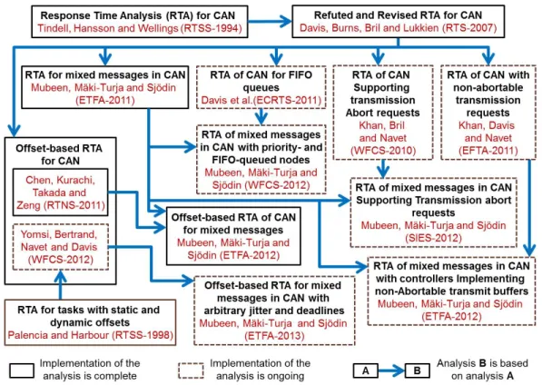
C. Implemented analysis
The analysis that we implemented (and continue to imple-ment) in MPS-CAN Analyzer consists of RTA for CAN and its several extensions as shown in Fig. 2. Solid-line boxes in Fig. 2 represent the analysis that is already implemented. Whereas, the dashed-line boxes represent the analysis whose implementation is ongoing. Fig. 2 also shows the relationship among the analyses.
IV. TOOLLAYOUT ANDUSAGE
A. Tool layout, inputs and outputs
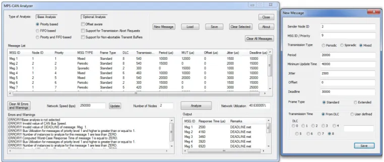
The Layout of MPS-CAN Analyzer is shown in Fig. 3. There are two windows: (1) main window denoted by “MPS-CAN Analyzer”, and (2) window denoted by “New Message”. The “MPS-CAN Analyzer” window is the user interface for the tool. The “New Message” window is used to create a new
message. It pops up when “New Message” button is clicked on the main window. The “New Message” window and upper portion of the main window including list boxes (“Message List”, “Network Speed” and “Number of Nodes”) and buttons (radio, check and push buttons) represent the input section of the tool. Whereas, the lower portion of the main window including “Output”, “Network Utilization”, and “Errors and Warnings” list boxes comprise the output section of the tool. In the main window, the base analysis must be selected. The base analyses is categorized based on the queueing policy in the CAN controllers, i.e., priority-based, FIFO-based, or both priority- and FIFO-based. Currently, priority-based analysis is implemented while the implementation of other two base analyses is ongoing. Once the base analysis is selected, one or more optional analysis may be selected that include (1) the analysis of messages that are scheduled with offsets, (2) the analysis supporting abortable transmit buffers, and (3) the analysis supporting non-abortable transmit buffers in the CAN controllers. Currently, the offset-aware analysis is implemented while the implementation of other two optional analyses is ongoing. The user can also specify network speed in bits per second (bps) in the main window. There are buttons provided to clear, save and load messages.
In the “New Message” window, message attributes are provided as input. For a mixed message, both period and minimum update time are specified. Whereas for a periodic or sporadic message, only period or minimum update time is specified respectively. The transmission type of a message can be selected from periodic, sporadic, or mixed. There are
Fig. 3. MPS-CAN Analyzer layout, inputs and outputs
two options for specifying transmission type of a message. First option is based on specifying Data Length Code (DLC), i.e., the number of data bytes present in the CAN message. The second option allows to specify user-defined transmission time. This option may be used for analyzing simplified test cases that are more suitable to research-oriented work.
Any message set can be analyzed by clicking the “Analyze” button. The “Errors and Warnings” list box displays the errors and warnings. Some example errors are shown in Fig. 3. The “Output” list box displays the calculated response times of the messages. It also displays whether a message meets its deadline or not (provided the deadline is specified by the user). The percentage network utilization is also calculated and displayed in the “Network Utilization” list box.
B. Implementation and distribution
The tool is implemented in C language. Each analysis profile supported by the tool is implemented as a separate C file. The tool has a scope for further extensions in the future. The link to the development version of the tool can be found at https://github.com/saadmubeen/MPS-CAN. The implementation of some extensions of RTA is ongoing. Once, the implementation is completed, the executables and source code of the tool will be provided on the above link.
C. Example case study
We perform an example case study to show the usability of the tool. The system in the example case study consists of two nodes that are connected to the CAN network. There are 10 messages in the system out of which four are mixed, two are sporadic and the rest are periodic. All the attributes of these messages are tabulated in the Table I. The attributes of a message m are identified as follows. The priority, transmission type, transmission time, period, minimum update time, offset, jitter, deadline and worst-case response time are represented by
Pm, ξm, Cm, Tm, M U Tm, Om, Jm, Dmand Rmrespectively. All timing parameters are in microseconds. The selected speed for CAN is 250000 bps. The worst-case response times calculated by MPS-CAN Analyzer are listed in the last column of Table 1. The network utilization calculated by MPS-CAN Analyzer for this message set is equal to 40.630005%.
V. CONCLUSION
We introduced a new tool MPS-CAN Analyzer to support Response Time Analysis (RTA) of periodic, sporadic and mixed messages in Controller Area Network (CAN). The ex-isting RTA tools for CAN analyze only periodic and sporadic messages. They do not support the analysis of mixed messages that are implemented by several higher-level protocols for CAN that are used in the automotive industry today.
We designated MPS-CAN Analyzer as many-in-one be-cause it implements various extensions of the RTA for CAN taking into account mixed messages, messages scheduled with offsets, messages with arbitrary jitter and deadlines, various queueing policies (e.g., priority- or FIFO-based), and limitations in the transmit buffers in the CAN controllers (e.g., abortable or non-abortable). Some extensions are already implemented while the implementation of the rest of the extensions is ongoing. We also showed the usability of this tool by conducting the analysis of example message set.
With the implementation of these analyses, MPS-CAN Analyzer will be able to analyze network communications in heterogeneous systems (which may consist of different types of ECU’s supplied by different Tier 1 suppliers). Once the implementation of all extensions of RTA for CAN is completed, we plan to conduct a detailed case study in which we will consider a heterogeneous system with ECUs implementing various queueing policies and having different buffer limitations. For example, some ECUs use priority-based queueing, some use FIFO-based queueing, and some support
TABLE I
ATTRIBUTES AND RESPONSE TIMES OF PERIODIC,SPORADIC AND MIXED MESSAGES
IDm Node ID Pm ξm DLC Cm(µs) Tm(µs) M U Tm(µs) Om(µs) Jm(µs) Dm(µs) Rm(µs)
1 1 1 Mixed 8 540 10000 12000 0 1500 10000 2580 2 2 2 Periodic 8 540 15000 - 0 2000 15000 4160 3 1 3 Sporadic 2 300 - 15000 0 1000 15000 3460 4 1 4 Mixed 6 460 10000 10000 0 1000 10000 3920 5 2 5 Mixed 8 540 20000 20000 0 3000 20000 6920 6 2 6 Periodic 2 300 15000 - 0 1500 15000 6260 7 1 7 Periodic 5 420 25000 - 0 3000 25000 8180 8 2 8 Sporadic 2 300 - 20000 0 3500 20000 8980 9 2 9 Mixed 8 540 20000 40000 0 4000 20000 9740 10 2 10 Periodic 1 260 20000 - 0 1800 20000 8080
transmission abort requests while others don’t. Since, this tool will be freely available, we believe, it may prove helpful in the research-oriented projects that require the analysis of CAN-based systems.
ACKNOWLEDGEMENT
This work in this paper is supported by the Swedish Knowl-edge Foundation (KKS) within the projects SythSoft and FEMMVA. The authors thank the industrial partners Arcticus Systems, BAE Systems H¨agglunds and Volvo Construction Equipment, Sweden.
REFERENCES
[1] Robert Bosch GmbH, “CAN Specification Version 2.0,” postfach 30 02 40, D-70442 Stuttgart, 1991.
[2] “Automotive networks. CAN in Automation (CiA),” http://www.can-cia.org/index.php?id=416.
[3] N. Audsley, A. Burns, R. Davis, K. Tindell, and A. Wellings, “Fixed priority pre-emptive scheduling:an historic perspective,” Real-Time Sys-tems, vol. 8, no. 2/3, pp. 173–198, 1995.
[4] K. Tindell, H. Hansson, and A. Wellings, “Analysing real-time com-munications: controller area network (CAN),” in Real-Time Systems Symposium (RTSS) 1994, pp. 259 –263.
[5] R. Davis, A. Burns, R. Bril, and J. Lukkien, “Controller Area Network (CAN) schedulability analysis: Refuted, revisited and revised,” Real-Time Systems, vol. 35, pp. 239–272, 2007.
[6] “Volcano Network Architect (VNA). Mentor Graphics,” http://www. mentor.com/products/vnd/communication-management/vna. [7] “Arcticus Systems,” http://www.arcticus-systems.com.
[8] S. Mubeen, J. M¨aki-Turja, and M. Sj¨odin, “Support for end-to-end response-time and delay analysis in the industrial tool suite: Issues, experiences and a case study,” Computer Science and Information Systems, ISSN: 1361-1384, vol. 10, no. 1, 2013.
[9] “CANopen Application Layer and Communication Profile. CiA Draft Standard 301. Version 4.02. February 13, 2002,” http://www.can-cia.org/index.php?id=440.
[10] “AUTOSAR Techincal Overview, Version 2.2.2., Release 3.1, The AUTOSAR Consortium, Aug., 2008,” http://autosar.org.
[11] “H¨agglunds Controller Area Network (HCAN), Network Implementa-tion SpecificaImplementa-tion,” BAE Systems H¨agglunds, Sweden (internal docu-ment), April 2009.
[12] R. I. Davis, S. Kollmann, V. Pollex, and F. Slomka, “Controller Area Network (CAN) Schedulability Analysis with FIFO queues,” in 23rd Euromicro Conference on Real-Time Systems, July 2011.
[13] R. Davis and N. Navet, “Controller Area Network (CAN) Schedulability Analysis for Messages with Arbitrary Deadlines in FIFO and Work-Conserving Queues,” in 9th IEEE International Workshop on Factory Communication Systems (WFCS), may 2012, pp. 33 –42.
[14] D. Khan, R. Davis, and N. Navet, “Schedulability analysis of CAN with non-abortable transmission requests,” in 16th IEEE Conference on Emerging Technologies Factory Automation (ETFA), sept. 2011. [15] D. Khan, R. Bril, and N. Navet, “Integrating hardware limitations in can
schedulability analysis,” in 8th IEEE International Workshop on Factory Communication Systems (WFCS), may 2010, pp. 207 –210.
[16] M. D. Natale, “Evaluating message transmission times in controller area networks without buffer preemption,” in 8th Brazilian Workshop on Real-Time Systems, 2006.
[17] Marco Di Natale, Haibo Zeng, Paolo Giusto, Arkadeb Ghosal, Un-derstanding and Using the Controller Area Network Communication Protocol. Springer, 2012.
[18] S. Mubeen, J. M¨aki-Turja, and M. Sj¨odin, “Extending schedulability analysis of controller area network (CAN) for mixed (periodic/sporadic) messages,” in 16th IEEE Conference on Emerging Technologies and Factory Automation (ETFA), sept. 2011.
[19] S. Mubeen, J. M¨aki-Turja and M. Sj¨odin, “Response-Time Analysis of Mixed Messages in Controller Area Network with Priority- and FIFO-Queued Nodes,” in 9th IEEE International Workshop on Factory Communication Systems (WFCS), May 2012.
[20] S. Mubeen, J. M¨aki-Turja, and M. Sj¨odin, “Response Time Analysis for Mixed Messages in CAN Supporting Transmission Abort Requests,” in 7th IEEE International Symposium on Industrial Embedded Systems (SIES), June 2012.
[21] S. Mubeen, J. M¨aki-Turja, and M. Sj¨odin, “Extending response-time analysis of mixed messages in can with controllers implementing non-abortable transmit buffers,” in 17th IEEE Conference on Emerging Technologies and Factory Automation (ETFA), sept. 2012.
[22] P. Yomsi, D. Bertrand, N. Navet, and R. Davis, “Controller Area Network (CAN): Response Time Analysis with Offsets,” in 9th IEEE International Workshop on Factory Communication Systems, May 2012. [23] A. Szakaly, “Response Time Analysis with Offsets for CAN,” Master’s thesis, Department of Computer Engineering, Chalmers University of Technology, Nov. 2003.
[24] M. Grenier, L. Havet, and N. Navet, “Pushing the limits of can-scheduling frames with offsets provides a major performance boost,” in 4th European Congress on Embedded Real Time Software, 2008. [25] Y. Chen, R. Kurachi, H. Takada, and G. Zeng, “Schedulability
com-parison for can message with offset: Priority queue versus fifo queue,” in 19th International Conference on Real-Time and Network Systems (RTNS), Sep. 2011, pp. 181–192.
[26] L. Du and G. Xu, “Worst case response time analysis for can messages with offsets,” in IEEE International Conference on Vehicular Electronics and Safety (ICVES), nov. 2009, pp. 41 –45.
[27] R. Henia, A. Hamann, M. Jersak, R. Racu, K. Richter, and R. Ernst, “System level performance analysis - the symta/s approach,” Computers and Digital Techniques, vol. 152, no. 2, pp. 148–166, March 2005. [28] S. Mubeen, J. M¨aki-Turja, and M. Sj¨odin, “Worst-case response-time
analysis for mixed messages with offsets in controller area network,” in 17th IEEE Conference on Emerging Technologies and Factory Automa-tion (ETFA), sept. 2012.
[29] S. Mubeen, J. M¨aki-Turja, and M. Sj¨odin, “Extending offset-aware response-time analysis for mixed messages in controller area network,” in 18th IEEE Conference on Emerging Technologies and Factory Au-tomation (ETFA), sept. 2013.
[30] “Vector. http://www.vector.com.”
[31] “CANalyzer. http://www.vector.com/vi canalyzer en.html.”
[32] “CANoe. www.vector.com/portal/medien/cmc/info/canoe productinfor-mation en.pdf.”
[33] A. Hamann, R. Henia, R. Racu, M. Jersak, K. Richter, and R. Ernst, “Symta/s - symbolic timing analysis for systems,” 2004.