Bluetooth mesh networks using
heterogeneous devices
MOHIT KUMAR AGNIHOTRI
Master’s Degree Project
Stockholm, Sweden August 2015
Master Thesis
Energy efficient topology formation for
Bluetooth mesh networks using
heterogeneous devices
Mohit Kumar Agnihotri
Supervisors:
Dr. Cicek Cavdar, Ph.D., KTH Wireless Francesco Militano, Senior Researcher, Ericsson Dr. Roman Chirikov, Ph.D., Experienced Researcher, Ericsson
Examiner:
Prof. Dr. Jens Zander, Ph.D., KTH Wireless
Internet of things (IoT) is the latest trend in our living spaces allowing machine to machine (M2M) communications at the extensive scale. To enable massive M2M communication and portable devices to run on limited power supplies for the extended duration of time, low-cost energy efficient wireless technologies are needed. Among the many competing technologies including Wi-Fi, Bluetooth has shown the potential to be one of the strong candidates to act as the connectivity solution for the IoT especially after the introduction of Bluetooth Low En-ergy (BLE). Nowadays BLE is one of the biggest players in the market of short-range wireless technologies. By 2020, nearly 30 billion BLE devices in the form of mobile phones, tablets, sports utilities, sensors, security systems and health monitors are expected to be shipped. This proliferation of low-cost devices may for the first time actualize the vision of IoT.
This thesis studies various mesh topology formation techniques that can be used to aid the development of large-scale networks in capillary networks focusing on BLE. In particular, the thesis focuses on how mesh networks can be established over BLE communications especially exploiting the heterogeneous characteristics of the devices. A novel algorithm is proposed called Topology Formation considering Role Suitability (TFRS) to maximize the network lifetime. The algorithm uses a newly introduced metric called role suitability metric (RSM) to assign the best role among master, relay and slave to a device. The RSM metric bases its decision on various device characteristics including, but not limited to, energy, mobility, and computational capabil-ity. We use the system-level simulation to evaluate the performance of the proposed algorithm against a reference under homogeneous deployment scenario consisting of heterogeneous de-vices.
Results show that the network lifetime can be improved significantly when the topology is formed considering the device characteristics for both master role selection and relay selection. TFRS can achieve moderate improvements ranging from 20% to 40% varying on the deploy-ment characteristics over the reference case.
I would like to first thank my advisors, Cicek Cavdar, Francesco Militano and Roman Chirikov, and acknowledge the guidance, encouragement, knowledge, support, patience, and assistance imparted to me over last six months. Your efforts helped me to harness the raw skills and tools I brought into this experience and accomplish what I would not have otherwise been able to do. I would also like to thank members of the WAN team, especially Yngve Sel´en, for providing an environment in which I felt welcomed and have been able to work side by side with such a talented research team.
I would like to thank my fellow students and friends for the technical help and moral sup-port they offered me. In particular, I wish to thank, Anita Sajwan, Bhanu Teja Kotte, Biniam Gebregergs, Joanna Alexander, and Pratheeksha Ml.
Finally, I would like to thank my family. Dad and Mom, you have always encouraged me to expand my horizons and expressed confidence in me even when I felt it was unwarranted.
1 Introduction 3
1.1 Capillary Network - A Viable Option . . . 3
1.1.1 Unique Challenges for Capillary Network . . . 4
1.2 Motivation . . . 4
1.3 Scenario . . . 6
1.4 Research Question . . . 6
1.5 Solution Approach . . . 7
1.6 Research Methodology . . . 7
1.7 Outline of the Thesis Contributions . . . 7
2 Background Study 9 2.1 Bluetooth Technology Review . . . 9
2.1.1 Physical Layer Operation . . . 10
2.1.2 Bluetooth BR/EDR Operation . . . 11
2.1.3 Bluetooth LE Operation . . . 12
2.1.4 Bluetooth Topology . . . 13
2.1.4.1 BR/EDR Topology . . . 13
2.1.4.2 LE Topology . . . 14
2.2 Network Lifetime . . . 14
2.2.1 Factors Affecting Network Lifetime . . . 15
2.3 Network Residual Energy . . . 16
2.4 Topology Formation Algorithm(s) . . . 18
2.4.1 WSN Topology Formation Algorithm(s) . . . 18
2.4.2 Bluetooth based Topology Formation Algorithm(s) . . . 19
2.5 Routing . . . 22
2.6 Research Gap(s) . . . 24
3 Problem Statement 27 3.1 Logical View of Problem . . . 27
3.2 Input Parameters & Explanation . . . 27
3.3 Objective . . . 29
3.4 Output Parameter . . . 29
4 Topology Formation considering Role Suitability (TFRS) 31 4.1 Role Suitability Metric (RSM) . . . 31
4.2 Proposed Algorithm . . . 33
4.3 Piconet Construction in Reference Algorithm . . . 34
4.3.1 Limitation(s) of the Reference Algorithm . . . 34
4.3.2 Piconet construction in Topology Formation considering Role Suitability (TFRS) . . . 35
4.4 Piconet Interconnection in Reference Algorithm . . . 37 ix
x CONTENTS
4.4.1 Limitation(s) of Reference Algorithm . . . 39
4.4.1.1 Gateway Prioritization . . . 39
4.4.1.2 Interconnect Rule(s) in Reference Algorithm . . . 41
5 Methodology 45 5.1 System Design . . . 45
5.1.1 Bluetooth Low Energy (BLE) Device . . . 45
5.1.1.1 BLE Device Design . . . 46
5.1.2 Transmission Manager . . . 47
5.1.3 Channel Capacity Model . . . 48
5.1.4 Power Model . . . 48
5.1.5 Routing Model . . . 49
5.1.6 Traffic Model . . . 50
5.2 Simulation Environment . . . 51
6 Performance Evaluation and Results 53 6.1 System Parameters . . . 53
6.2 Simulation Results . . . 54
6.2.1 TFRS versus Reference algorithm . . . 55
6.2.2 Impact of Master Role Selection . . . 55
6.2.3 Impact of Gateway Selection . . . 57
6.2.4 Impact of Device-Type Ratio . . . 58
6.2.5 Impact of Device Density . . . 58
6.3 Limitation(s) of Simulations . . . 60
7 Summary & Outlook 63 7.1 Discussion . . . 63
7.2 Future Work . . . 64
Appendix A Impact of Master Selection on Network lifetime 75 Appendix B Impact of Gateway Selection on Network lifetime 79 Appendix C Impact of Algorithms on Network lifetime 83 Appendix D Device Survey 87 D.1 Rechargeable Battery Capacity . . . 87
1.1 End-to-end architecture for capillary networks . . . 4
1.2 Increasing traffic & revenue gap . . . 5
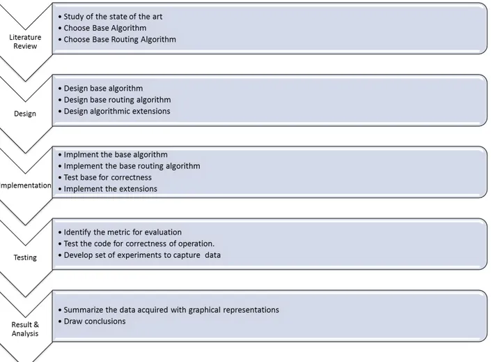
1.3 Research methodology followed in the study . . . 8
2.1 Bluetooth host and controller combinations . . . 10
2.2 Piconet and scatternet topologies . . . 11
2.3 Bluetooth BR/EDR topology . . . 13
2.4 Bluetooth LE topology . . . 14
2.5 Topological possibilities for devices . . . 16
2.6 Example topology . . . 17
2.7 Network lifetime with and without relay maintenance . . . 17
3.1 Block design for the framework . . . 28
3.2 Topology formation and routing framework . . . 28
4.1 Relative energy of devices . . . 33
4.2 Piconet creation . . . 35
4.3 Piconet creation . . . 36
4.4 Optimized piconet with RSM or RSMN . . . 37
4.5 Possible interconnect(s) between piconets . . . 39
4.6 Piconet creation . . . 41
4.7 Piconet interconnection . . . 42
4.8 Impact of prioritization rule on gateway selection . . . 42
5.1 BLE mesh system design . . . 45
5.2 BLE device design overview . . . 46
5.3 Modular view of BLE characteristics module . . . 47
5.4 Transmission manager . . . 48
5.5 BLE device power dissipation characteristics . . . 49
5.6 Route discovery in a connected graph . . . 50
5.7 Flow chart for simulation design . . . 52
6.1 Network lifetime for TFRS . . . 56
6.2 Network lifetime for master selection strategies . . . 57
6.3 Network lifetime for gateway selection strategies . . . 58
6.4 Impact of device-type density on network lifetime . . . 59
6.5 Impact of device density on network lifetime . . . 60
A.1 Impact of Master Selection on Network lifetime - A . . . 76
A.2 Impact of Master Selection on Network lifetime - B . . . 77
B.1 Impact of Gateway Selection on Network lifetime - A . . . 80 xi
xii LIST OF FIGURES
B.2 Impact of Gateway Selection on Network lifetime - B . . . 81 C.1 Impact of TFRS on Network lifetime - A . . . 84 C.2 Impact of TFRS on Network lifetime - B . . . 85
1.1 Device characteristics . . . 7
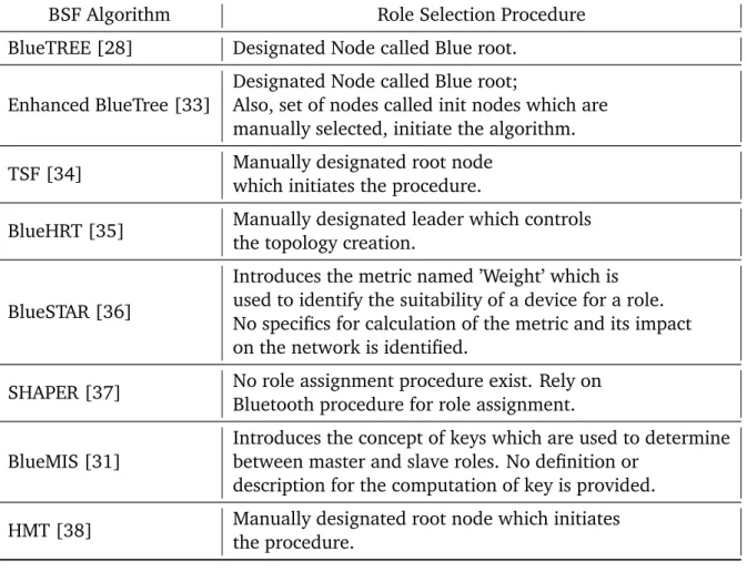
2.1 Summary of topology formation algorithms . . . 22
2.2 Review of device role selection methodologies . . . 23
4.1 Device characteristics . . . 31
4.2 Description of device characteristic that can be used to derive role metric . . . 32
4.3 RSM & RSMN Metric for the devices . . . 36
4.4 Set of interconnect rules . . . 40
4.5 Set of interconnect rules as defined in TFRS . . . 44
6.1 Summary of system parameters . . . 55
D.1 Survey of rechargeable devices battery capacity . . . 87
D.2 Survey of BLE devices battery capacity . . . 87
1 Role specific metric computation . . . 37
2 RSM with neighbour Computation . . . 38
3 Node comparison with RSM . . . 38
4 Gateway selection using Reference with Energy . . . 43
5 Gateway selection using energy . . . 43
AODV Ad hoc On-Demand Distance Vector. 28
BLE Bluetooth Low Energy. x, xiii, xv, 3, 6, 7, 18, 36, 38, 51–55, 87 BR Basic Rate. 11–15
BSF Bluetooth Scatternet Formation. 23, 35, 37, 39, 72
BSF-UED Bluetooth Scatternet Formation (BSF) with Unnecessary-Edges Deletion. 37 BTCP Bluetooth Topology Construction Protocol. 23
CDMA Code Division Multiple Access. 22 CH cluster head. 20, 22, 29
DSDV Destination-Sequenced Distance-Vector. 28 DSR Dynamic Source Routing. 28
DWEHC Distributed Weight-based Energy-Efficient Hierarchical Clustering. 22 EDR Enhanced Data Rate. 11–15
FDMA Frequency Division Multiple Access. 14, 15 FHSS Frequency Hopping Spread Spectrum. 14 HCI Host Controller Interface. 12
HEED Hybrid Energy Efficient Distributed. 22 IoT Internet of Things. 71
ISM Industrial, Scientific and Medical. 11, 12, 14
L2CAP Logical Link Control and Adaptation Protocol. 11 LE Low Energy. 11, 12, 14
LEACH Low Energy Adaptive Clustering Hierarchy. 20, 22 M2M Machine-to-Machine. 3, 4
MAC Media Access Control. 12
Acronyms 1
mAh Milliampere-hour. 61, 62
OLSR Optimized Link State Routing. 28 PAL Protocol Adaptation Layer. 12 PHY Physical. 12, 13, 15
QOS Quality of Service. 4 RF Radio Frequency. 13
RSM role suitability metric. 35, 36, 40 Rx Reception. 55
TDD Time-Division Duplex. 14
TDMA Time Division Multiple Access. 14, 15, 22
TFRS Topology Formation considering Role Suitability. x, xiii–xv, 37, 40, 43, 46, 49, 63, 64,
67, 72, 85, 86
TORA Temporally Ordered Routing Algorithm. 28 Tx Transmission. 55
TxRx Transmission/Reception. 53, 62 WCA Weighted Clustering Algorithm. 22 WSN wireless sensor networks. 3, 6, 20, 22, 29 ZRP Zone Routing Protocol. 29
Chapter 1
Introduction
The Machine-to-Machine (M2M) communication implies the ability of machines to communi-cate without human intervention [1][2]. Lack of interaction places stringent requirement as there is no control during data communication and minimal servicing of the system at large, such as changing batteries. With emerging applications such as smart homes, smart cities, M2M traffic has seen an exponential increase in last few years. The M2M devices such as automatic meter readers are characterized by very low data rates, small data packets, and low mobility re-quirements but are expected to outnumber voice and data terminals significantly in the coming years. Allowing smoother transition, ETSIs (European Telecommunication Standards Institute) M2M Technical Committee has proposed a hybrid architecture whereby cellular-enabled gate-ways (GW) act as traffic aggregation and protocol translation points for their capillary networks. Capillary networks, in turn, are composed of a potentially high number of devices (e.g. sensors) equipped with short-range radio interfaces, such as IEEE 802.11, Bluetooth, ZigBee, etc. [3]. With a huge number of machines, efficient communication becomes a great challenge. Many techniques and protocols inspired from the existing work in the field of wireless sensor networks (WSN) have been investigated to improve energy efficiency in M2M capillary networks, such as resource management, data aggregation and clustering [4] [5]. This study focuses on the problem of topology formation and clustering in capillary networks maximizing network life-time considering BLE as the connectivity technology between devices. This chapter introduces the area, the motivation of the work, research questions and contribution of the thesis.
1.1
Capillary Network - A Viable Option
The capillary network constitutes a multitude of communication methods where the main ob-jective is to reduce the overhead on the core infrastructure and promote spectrum reuse or use of alternate spectrum. The capillary networks are specifically preferred for M2M type communi-cation as they provide an efficient paradigm for connecting a large number of devices employing short-range communication technology. It enables aggregation of non-3GPP technologies like Bluetooth, Wi-Fi, ZigBee, etc. allowing spectral reuse. A capillary network may comprise of homogeneous or heterogeneous devices, each using one or more short-range communication technology employing single or multiple hops for data communications. These networks are being considered as a prospective option for connecting the various devices in proximity. The figure 1.1 provides a bird-eye view of a possible capillary network architecture.
1.1.1 Unique Challenges for Capillary Network
The capillary networks must adhere to the requirements of reliability, latency and connectivity imposed by innovative use-cases outlined for the fifth generation of communication infrastruc-ture [6]. Meeting these requirements especially in capillary networks is difficult owing to the atypical nature of devices.
It is envisioned that capillary networks would be used to enable M2M communication for the sensor type devices. These devices are characterized by limited power, compute and memory resources. Under these added constraints, the operational characteristic of the underlying short range radio technology used to enable the capillary network become critical to meet architec-tural needs. The technology must be able to minimize the delay, maximize networks operational lifetime while meeting the Quality of Service (QOS) requirements.
Irrespective of the enabling technology, the two aspects of which play a decisive role in delivering aforementioned requirements are: 1) How are the devices connected? Moreover, 2) How is the data transmitted over the multi-hop architecture? These can be classified as topology formation and routing aspects of the technology.
Figure 1.1: End-to-end architecture for capillary networks [7]
1.2
Motivation
It is evident that the number of devices is growing, and user requirements are getting stringent. In order fulfil increasing demand, multiple technological solutions using Bluetooth, ZigBee, Wi-Fi etc. as the technology, have been proposed to solve connectivity and data aggregation and routing problems [8][9] [10], each with idiosyncratic pros and cons. The viability of the pro-posed solutions depends on multiple factors including financial and technological.
A solution that is both technically feasible i.e. best in the performance and has a robust busi-ness case especially in terms of cost is most likely to dominate among many proposed solutions. An attempt has been made to understand the challenges considering the business case, along the technical limitations of the proposed solution(s) allowing us to better the technology and strengthen the business case.
1.2. MOTIVATION 5
Figure 1.2: Increasing traffic & revenue gap [13]
when compared to the conventional cellular network. It mostly due to the sheer number of devices, exceeding the elements in the current network by several orders of magnitude. While the number has been growing, a provider is still required to perform the three core functions i.e. deployment, management and maintenance of the network nodes.
On the other hand, the telecommunication industry has been witnessing negative trends in revenue. The gap between traffic carried by the network and the associated revenue is increasing[11] (fig 1.2). This is an increasing concern as operators have indicated that continuing trend could threaten their ability to invest in essential capacity to provide next-generation communication services [12].
These challenges require innovative methods to simplify and reduce the associated cost for deployment, management and maintenance. Multiple solutions have been proposed to minimize the complexity of the network management aspects. It is recommended not to consider the nodes in a capillary network as individual nodes but economy of scale can be achieved by handling them in groups that use policies and managed parameters that are more abstract and also fewer in number [7]. Given the devices in the network are energy constrained, it is highly desired to increase the operational lifetime of the network. It would result in cost-efficient operation owing to replacing sensor batteries less frequently and reduced associated personal cost.
The Technical Prospective: among the various competing technologies for enabling capillary
networks, BLE is one of the prime candidates to be a favoured technology. The inclination is driven by the wide acceptance of the technology, low cost and recent development in energy efficient operation enabling extended period of operation on a coin cell battery. The latest developments give it an edge, but the inherent design of the Bluetooth creates few challenges that must be overcome before BLE can be truly favoured.
The limitation arises from the Bluetooth communication topology that allows only direct i.e. single hop communication between a master and slave device. There is no direct com-munication between two slave devices. This means that although there is no theoretical limit to the number of Bluetooth devices that share a master, there is a limit to the num-ber of these devices that can be actively involved in exchanging data with the master[14]. This limits communication capabilities in a star-like topology with the master at the centre.
The Bluetooth supports the possibility of having multiple masters for a slave device, thereby making it a relay. Using relay type functionality require a certain degree of topol-ogy creation and routing over it but the Bluetooth core specification denies any possibility of assuming these services from the Bluetooth protocol stack. As per the specification ”Involvement in multiple networks (scatternet) does not necessarily imply any network routing capability or function in the Bluetooth device. The Bluetooth core protocols do not, and are not intended to offer such functionality, which is the responsibility of higher level protocols and is outside the scope of the Bluetooth core specification.”[14].
In order to meet the requirements for increased network lifetime and the limitations of the Bluetooth technology, it is necessary to formulate efficient algorithms for topology creation and routing in order to achieve efficient multi-hop communication between the devices. The research community has extensively focused on developing algorithms for the efficient topology creation especially in the field of WSN while last decade has seen an increase in interest for Bluetooth based topology formation algorithms.
1.3
Scenario
The current studies considering the home or office automation are the primary scenarios ex-tending the vision of smart cities. It is also motivated by real-life use-cases and the undergoing work in Bluetooth SIG (mesh). The scenario is characterized by the homogeneous deployment of heterogeneous devices in an office or home space. These devices are categorised depending on the nature of energy supply i.e. connected, rechargeable and coin-cell battery. Example of such devices can be washing machine, mobile phone, temperature sensors, etc.
These devices are assumed to be homogeneously distributed since, in an office or home environment, most of the resources are planned to be easily accessible, for example, printers or coffee machines in a large office space. Also, owing to the symmetry in building design, sensors like temperature or pressure or security are also homogeneously distributed.
1.4
Research Question
The broad goals of the thesis can be further broken down into simpler, focused and quantifiable research questions.
The first question aims to identify the limiting characteristics or assumptions of the existing topology formation algorithms which impact the operations lifetime of the network. This ques-tion can be formulated as
“Q1: What are the limiting characteristics or assumptions of Bluetooth based topology formation algorithms for a deployment of heterogeneous devices?”
The second research question aims to uncover the prospective gain in the network’s opera-tional lifetime by exploiting the heterogeneous nature of the devices.
“Q2: How much improvement in the network lifetime can be achieved for BLE mesh networks by exploiting heterogeneous device characteristics during topology formation?”
1.5. SOLUTION APPROACH 7
1.5
Solution Approach
The master thesis focuses on analysing the various factors which impact the operational lifetime of the capillary network using Bluetooth as the enabling technology and to develop a topology formation algorithm considering heterogeneous device characteristics to maximize the network lifetime as shown in table 1.1. The devices in the network are deemed to be heterogeneous, each having separate energy, compute and memory profile. The topology creation algorithms are reviewed to identify the current gaps and propose new algorithms or extensions to improve the network lifetime. For the scope of master thesis, devices are characterised into following categories as given in table 1.1.
Device characteristic Possible values
Compute High Appliance Sensor
Energy Connected Rechargeable
battery
Coin cell battery
Memory High Appliance Sensor
Table 1.1: Device characteristics
1.6
Research Methodology
The current study progressed in multiple phases: 1) background and literature survey, 2) sys-tem design, 3) algorithm implementation, 4) simulation and 5) result and analysis phase.
The background study phase is aimed to understand the details of the Bluetooth technology and related work in the field of topology formation. System design phase conceptualizes the detailed software architecture for the simulation environment which is used for comparative analysis of the proposed algorithm. In the final phase, data collected from the simulation are analysed to derive a conclusion. The figure 1.3 presents the step-by-step process followed in the study.
1.7
Outline of the Thesis Contributions
The thesis and its contributions to the mesh networking using Bluetooth are structured in three parts.
• The first part presents the background related to the Bluetooth technology, network life-time and an extensive survey of the topology formation algorithms presenting the limita-tions and various assumplimita-tions which restrict the usage of the algorithms to specific cases. The review also provides insight into various shortcoming of the algorithms considering the heterogeneous nodes in a deployment.
• The second part presents the proposed topology formation algorithm with the role suit-ability. A detailed description of the algorithm, its limitations, and simulation setup is presented, allowing reproducibility and repeatability of the simulations.
Figure 1.3: Research methodology followed in the study
• Finally the third part, presents the performance of the proposed algorithm compared to the reference. It is shown that network lifetime can be significantly increased by consid-ering heterogeneous characteristics of devices during the topology formation.
Chapter 2
Background Study
The chapter aims to provide a brief introduction of the Bluetooth technology, outlining the concepts and ideas relevant to the work. These concepts are further elaborated to gain an understanding of the operational structure and the perceived limitations of the technology. The reader is encouraged to visit [14] for the detailed descriptions of the Bluetooth fundamentals as the presented text provides very basic understanding and re-uses text and examples from the standard [14]. The section 2.2 introduces the network lifetime and the adopted definition for the work. Section 2.4 introduces existing work in the area of topology formation and later section 2.5 broadly introduces the routing techniques and the preferred methodology for the work. Finally the section 2.6 outlines the identified limitation and the defines the focus of the work.
2.1
Bluetooth Technology Review
Bluetooth is a short-range communication technology aiming to replace wires over small dis-tances. It operates in 2.4 GHz range which is reserved for Industrial, Scientific and Medical (ISM) use. This free-rent policy allows endless technologies to operate in the spectrum, few to mention are Wi-Fi, ZigBee, microwave, etc. creating interference and requiring Bluetooth to be robust along with low power and low cost.
There are two types of Bluetooth devices: Basic Rate (BR) and Low Energy (LE). These devices include basic functionalities to perform device discovery, connection establishment and connection mechanism. These functionalities enable a Bluetooth device to detect neighbouring devices, connect and transfer data among them. The BR device may optionally have support for the Enhanced Data Rate (EDR), enabling faster data communication between the devices. A Bluetooth system is split into two logical entities, namely, host and controller.
Host: it is defined as a group of protocols for control and data multiplexing. It comprises of
Logical Link Control and Adaptation Protocol (L2CAP) which is primarily responsible for multiplexing and de-multiplexing. Also, security and profiles are defined here enabling and dictating access to reusable device resources. It is possible to split the host application, the host, and the controller physically.
Controller: it is the radio module responsible for the reception and the transmission of
pack-ets. The Bluetooth specification [14] dictates that a Bluetooth device can have one pri-mary and multiple secondary controllers. The pripri-mary controller is comprised of exactly one of BR/EDR or LE or combined BR/EDR and LE as the primary controller. In addi-tion, there can be multiple secondary controllers including an 802.11 Protocol Adaptation Layer (PAL), 802.11 Media Access Control (MAC) and Physical (PHY), and optionally Host
(a) LE only pri-mary controller
(b) BR/EDR only primary controller
(c) BR/EDR primary controller with one AMP secondary con-troller
(d) BR/EDR with multiple AMP secondary controller
(e) BR/EDR and LE primary con-troller
(f) BR/EDR and LE primary con-troller with one AMP secondary controller
(g) BR/EDR and LE primary con-troller with multiple AMP sec-ondary controller
Figure 2.1: Bluetooth host and controller combinations
Controller Interface (HCI). Various possible valid combinations of Bluetooth host and con-troller are represented in figure 2.1.
2.1.1 Physical Layer Operation
Bluetooth operates in ISM band. Depending on the controller i.e. BR/EDR or LE, a device may use 80 or 40 channels spaced at 1 MHz or 2 MHz. The first channel starts at 2042 MHz and con-tinues up to 2480 MHz. The lowest architectural layer in the Bluetooth system is the physical channel. A number of types of physical channels are defined which are characterized by the combination of a pseudo-random frequency hopping sequence, the specific slot timing of the transmissions, the access code and packet header encoding. These aspects, together with the range of the transmitters, define the signature of the physical channel.
Two devices that wish to communicate use a shared physical channel for this communica-tion. To achieve this, their transceivers must be tuned to the same Radio Frequency (RF) at the same time, and they must be within a nominal range of each other. Given that the number of RF carriers is limited and that many Bluetooth devices could be operating independently within the same spatial and temporal area there is a strong likelihood of two independent Bluetooth devices having their transceivers tuned to the same RF carrier, resulting in a physical channel collision. To mitigate the unwanted effects of the collisions each transmission on a physical channel starts with an access code that is used as a correlation code by devices tuned to the physical channel. The access code is a property of the channel and is always present at the start
2.1. BLUETOOTH TECHNOLOGY REVIEW 11
of every transmitted packet.
Five Bluetooth physical channels are defined. Each is optimized and used for a different purpose.
• Basic and Adapted piconet channel: they are used for communication between connected devices and are associated with a specific piconet.
• Inquiry scan channel: it is used for discovering Bluetooth devices. • Page scan channel: it is used for connecting Bluetooth devices.
• Synchronization scan channel: it is used by devices to obtain timing and frequency infor-mation about the Connectionless Slave Broadcast physical link or to recover the current piconet clock.
A Bluetooth device can only use one of these physical channels at any given time. To support multiple concurrent operations, the device uses time-division multiplexing between the chan-nels. In this way, a Bluetooth device can appear to operate simultaneously in several piconets, as well as to be discoverable and connectable.
The Bluetooth system provides a point-to-point (figure 2.2(a)) or a point-to-multipoint con-nection(figure 2.2(b)). One Bluetooth device acts as the master of the piconet, whereas the other device(s) act as a slave(s). Piconets that have common devices are called scatternet (fig-ure 2.2(c)). Each piconet has a single master. However, slaves can participate in different piconets on a time-division multiplex basis. Also, a master in one piconet can be a slave in other piconets.
Figure 2.2: Piconet with a single slave operation (a) a multi-slave operation (b) and a scatternet operation (c)[14]
2.1.2 Bluetooth BR/EDR Operation
The BR / EDR radio PHY uses a shaped, binary frequency modulation to minimize transceiver complexity. During typical operation, a physical radio channel is shared by a group of devices that are synchronized to a common clock and frequency hopping pattern. One device provides the synchronization reference and is known as themaster. All other devices synchronized to
a master’s clock and frequency hopping pattern are known asslaves. A group of devices
the Bluetooth BR/EDR wireless technology.
Devices in a piconet use a specific frequency hopping pattern, which is algorithmically de-termined by certain fields in the Bluetooth address and clock of the master. The basic hopping pattern is a pseudo-random ordering of the 79 frequencies, separated by 1 MHz, in the ISM band. The hopping pattern can be adapted to exclude a portion of the frequencies that are used by interfering devices. The adaptive hopping technique improves co-existence with static (non-hopping) ISM systems when they are co-located. Frequency hopping takes place between the transmission or reception of packets. Bluetooth technology provides the effect of full duplex transmission through the use of a Time-Division Duplex (TDD) scheme.
Typically within a physical channel, a link is formed between a master device and slave devices. Exceptions to this include inquiry and page scan physical channels, which have no associated physical link. The link provides bi-directional packet transport between the master and slave devices, except in the case of a connectionless slave broadcast physical link. In that case, the link provides a unidirectional packet transport from the master to a potentially unlim-ited number of slaves. Since a physical channel could include multiple slave devices, there are restrictions on which devices may form a physical link. There is a link between each slave and the master. The physical links are not formed directly between the slaves in a piconet.
2.1.3 Bluetooth LE Operation
The LE system employs a frequency hopping transceiver to combat interference and fading and provides many Frequency Hopping Spread Spectrum (FHSS) carriers. The radio operation uses a shaped, binary frequency modulation to minimize transceiver complexity. It employs two multiple access schemes: Frequency Division Multiple Access (FDMA) and Time Division Mul-tiple Access (TDMA). Forty (40) physical channels, separated by 2 MHz, are used in the FDMA scheme. Three (3) are used as advertising channels, and 37 are used as data channels. A TDMA based polling scheme is used in which one device transmits a packet at a predetermined time, and a corresponding device responds with a packet after a predetermined interval. The physical channel is sub-divided into time units known as events. Data is transmitted between LE devices in packets that are positioned at events.
There are two types of events: Advertising and Connection events. Devices that transmit advertising packets on the advertising PHY channels are referred to as advertisers. Devices that receive advertising packets on the advertising channels without the intention to connect are called scanners. Transmissions on the advertising PHY channels occur in advertising events. At the start of each advertising event, the advertiser sends an advertising packet corresponding to the advertising event type. Depending on the kind of advertising packet, the scanner may make a request to the advertiser. LE devices may fulfil the entire communication in the case of unidirectional or broadcast type between two or more devices using advertising events.
They may also use advertising events to establish pair-wise bidirectional communication between two or more devices using data channels. Devices that need to form a connection to another device listen for connectable advertising packets. Such devices are referred to as initiators. If the advertiser is using a connectable advertising event, an initiator may make a connection request using the same advertising PHY channel on which it received the con-nectable advertising packet. The advertising event is ended, and connection events begin if the advertiser receives and accepts the request for a connection be initiated. Once a connection is established, the initiator becomes themaster device in what is referred to as a piconet, and the
2.1. BLUETOOTH TECHNOLOGY REVIEW 13
advertising device becomes theslave device. Connection events are used to send data packets
between the master and slave devices. Within a connection event, the master and slave alter-nate sending data packets using the same data PHY channel. The master initiates the beginning of each connection event and can end each connection event at any time [14].
2.1.4 Bluetooth Topology
2.1.4.1 BR/EDR Topology
Anytime a link is created using the BR/EDR controller it is within the context of a piconet. A piconet consists of two or more devices that occupy the same BR/EDR physical channel. The terms master and slave are only used when describing these roles in a piconet.
A number of independent piconets may exist nearby. Each piconet has a different physical channel (that is a different master device and an independent timing and hopping sequence). A Bluetooth device may participate concurrently in two or more piconets. It does this on a time-division multiplexing basis. A Bluetooth device can never be a master of more than one piconet. (Since in BR/EDR the piconet is defined by synchronization to the master’s Bluetooth clock it is impossible to be the master of two or more piconets.) A Bluetooth device may be a slave in many independent piconets. A Bluetooth device that is a member of two or more piconets is said to be involved in a scatternet. Involvement in a scatternet does not necessarily imply any network routing capability or function in the Bluetooth device.
Figure 2.3: Bluetooth BR/EDR topology[14]
In Figure 2.3 an example topology is shown that demonstrates a number of the architectural features described below. Device A is a master in a piconet (represented by the shaded area) with devices B, C, D and E as slaves. Three other piconets are shown: a) one piconet with device F as master and devices E, G and H as slaves, b) one piconet with device D as master and device J as slave, and c) one piconet with device M as master and device E as a slave and many devices N as slaves.
2.1.4.2 LE Topology
In Figure2.4 an example topology is shown that demonstrates a number of the LE architectural features. Device A is a master in a piconet (represented by the shaded area) with devices B and C as slaves. Unlike BR/EDR slaves, LE slaves do not share a common physical channel with the master. Each slave communicates on a separate physical channel with the master. One other piconet is shown with device F as master and device G as a slave. Device K is in a scatternet. Device K is master of device L, and slave of device M. Device O is also in a scatternet. Device O is the slave of device P and the slave of device Q.
Figure 2.4: Bluetooth LE topology[14]
2.2
Network Lifetime
The lifetime for a battery-powered device can be defined as the duration of time for which it can operate before degrading its battery to a point where it can’t perform basic functionalities. The definition can be extended to a network, where the network’s lifetime is dependent on the devices participating in the network and can be defined as the duration of time during which the network can provide the expected functionality to the participating devices. It is very closely linked to the devices in the network and their energy characteristic like energy source type and dissipation rate.
In the literature, there are numerous articles which address the problem of network lifetime in the context of the topic being addressed and propose various methods to estimate it. These definitions are analysed in the purview of the current work and most suitable is chosen as the preferred method of lifetime calculation in current work.
• Single failure: the network lifetime is defined as the duration of the time until the first device in the network fails. For a given topology with N device and Tn as lifetime of a
device, it can be given as:
Lif etime = min
2.2. NETWORK LIFETIME 15
The definition was used in the work [15] with slight modification where the sink node was excluded to indicate an infinite power supply. The metric suffers from the limitation that it is very basic and doesn’t consider the cases where due to the network redundancy, required functionality is still available. The metric can only be successfully used if the net-work considers all nodes with equal importance and are critical to delivering the necessary functionality [16].
• m-of-n failures: the definition extends the first device failure to incorporate for the possi-ble redundancies in the network. It defines the lifetime as the duration of time before m devices in the network runs out of energy.
The definition is better considering the single failure, but it lacks accuracy as pointed out by Dietrich and Dressler. Consider the case when m′ < m nodes at strategic positions (perhaps around the base station) fail and the remaining nodes now have no possibility of transmitting any data the sink. Then the network should not be considered alive, but the metric does not recognize this until another m − m′ nodes have failed [16].
• Clustered m-of-n failures: it was first introduced by Hellman and Colagrosso in [17]. The nodes are divided into two groups namely critical and non-critical based upon the role they play in the network operations. The definition allows for k out of m failures in the non-critical and no failure in the critical category. This definition improves on the aspect of treating all devices equally but still has limitation discussed for ”m-of-n failures”. The current work focuses on heterogeneous devices forming a fully connected mesh network and usage of Bluetooth as the technology allows easy classification of the device into critical and non-critical. With these assumptions, ”clustered m-of-n failures” is the best-suited method for estimating network lifetime. The devices acting as ”Master” and ”Relay” are classified as critical, and all the slaves are non-critical devices. In the adopted definition, it is allowed to have ”K of K” failure in the non-critical cluster, while ”0 of M” are allowed in the critical cluster. The first failure in the critical cluster defines the lifetime of the network.
For a network with N devices, M critical and K non-critical, the network lifetime can be given by equation 2.2.
Lif etime = min
m∈MTm (2.2)
2.2.1 Factors Affecting Network Lifetime
Given the definition of the lifetime, it is important to understand the various topological, routing and technology factors which impact the energy dissipation and thereby affecting the network lifetime.
Under the purview of Bluetooth as the technology, it is important to consider following as-pects to obtain maximal network lifetime. In the current thesis, we focus on the problem of device role selection while topology adaptation and routing are mentioned for the complete-ness. We consider heterogeneous devices in the network and aim to uses their characteristics to formulate rules for assigning roles to the devices.
1. Device Role Selection: in the BLE scatternet, we have three kinds of devices as earlier outlined i.e. master, relay, and slave. It is recommended to assign these roles based on the device characteristics as master and relay nodes are used to enable inter and intra-piconet communication. Any algorithm which uses device characteristic based metric to assign these roles must be preferred over random role assignment. For example, it is optimal
5 2 9 3 8 4 7 6 1
(a) Random role selection
5 2 9 3 8 4 7 6 1
(b) Characteristics based role selec-tion
Figure 2.5: Various Device Connection Possibilities (Green: Master; Blue: Slave and higher Id indicate better suitability for master role)
to assign ”master” role to a device with maximum energy. The node with second highest energy should be assigned the ”relay” role.
In the figure 2.5, an example of random and characteristics based role selections is pro-vided. The topology as depicted in figure 2.5b must be preferred over 2.5a as it allows a device with the maximum capability to be chosen as a master.
2. Topology Adaptation: as the network become operational, the energy at various nodes is consumed. The master and the relay nodes are worst affected owing to extra responsi-bility of relaying the traffic. Therefore, it is beneficial to alternate the role of the master and relay among several nodes. Thus, it is important for a topology formation algorithm to have a maintenance phase where options for suitable master and relays can be period-ically evaluated, and role can be switched if deemed necessary.
For example, let us assume two piconets with M 1 and M 2 as the master and R1, R2 and
R3as possible relays between them. Initially, all of them have 100% energy, and R1 is chosen as the relay. The rate of energy dissipation for a slave is 1 unit/sec and for a relay is 3 unit/sec while all the masters are connected to mains. The resulting topology is presented in figure 2.6. Let’s assume there are two algorithms, one with maintenance phase and one without, the network lifetime can be given by the following graphs in the figure 2.7. It is evident that existence of maintenance phase in the algorithm enhances the network lifetime by switching the nodes in master or relay roles.
3. Routing Algorithm: this plays a significant role as all inter-piconet communication must be routed. The routing algorithm generally performs two steps i.e. route discovery and packet forwarding along the discovered route. The methodology utilized to achieve these fundamental operations impact the network lifetime of the network.
2.3
Network Residual Energy
This is the measure of the total energy in the network at any point in time. It is calculated by summing over the residual energy of all the nodes in a deployment. The metric can be used to estimate the impact of the routing algorithm on the underlying topology. Failure of the critical device marks the end of the network lifetime, comparison of the residual energy at that instant
2.3. NETWORK RESIDUAL ENERGY 17 R2 M1 R3 R1 M2 Prospective Relays
Figure 2.6: An example topology with multiple relays
Network lifetime (seconds)
0 5 10 15 20 25 30 35
Relay Node Energy (mAh)
-20 0 20 40 60 80 100 Device R1 Device R2 Device R3
(a) Relay operation without maintenance phase
Network lifetime (seconds)
0 10 20 30 40 50 60
Relay Node Energy (mAh)
-20 0 20 40 60 80 100 Device R1 Device R2 Device R3 Relay Switchover
(b) relay operation with maintenance phase
allows us to determine if a routing hot-spot is responsible for the failure of the critical node or not.
2.4
Topology Formation Algorithm(s)
The problem of topology formation has been extensively studied in the field of WSN. A WSN consists of spatially distributed nodes, communicating using wireless methodologies. They are required to operate autonomously without human intervention. Given the sensors have limited resources, it is important to design an algorithm which consider these limiting characteristics.
2.4.1 WSN Topology Formation Algorithm(s)
In WSN, for the efficient data aggregation and network management, nodes are divided into groups called clusters, and the process is termed as clustering. Each cluster has a designated cluster head (CH) which handles scheduling activities and communication in the cluster. Fol-lowing are few of the prominent clustering protocols.
• Low Energy Adaptive Clustering Hierarchy (LEACH) [18]: the algorithm aims to distribute the energy consumption evenly across the network. The network is divided into clusters formed by randomly elected CHs. The protocol operates in four distinct phases: 1) adver-tisement 2) cluster setup 3) schedule creation and 4) data transmission. The energy drain for the cluster head is limited by randomizing the CH.
The main advantages of the algorithm are: 1) load is equally shared among the cluster heads. 2) Usage of TDMA with Code Division Multiple Access (CDMA) minimizes colli-sions and interference from nearby clusters. However, there are few disadvantages. 1) load balancing relies only on the probability of election without the consideration of the initial energy of the nodes. 2) Frequent election of CH brings overhead and may diminish the gain in energy consumption. 3) CHs are randomly elected.
• Hybrid Energy Efficient Distributed (HEED) [19]: it is a distributed algorithm where clus-ter heads are elected based on the residual energy and communication cost avoiding ran-dom selection of CHs. The algorithm executes in three phases: initialization, repetition, and finalization phase.
The probability for a node to be elevated to the role of CH if it has the highest energy and minimum inter-piconet communication cost. The algorithm supports the possibility of heterogeneous nodes as it accounts for the initial energy, and it can vary for each node. The main advantages of the algorithm are: 1) better load balancing by using multiple parameters for CH election. 2) multi-communication over single hop, allowing energy conservation. However, there are few limitations. 1) Performing of clustering for each round of operation imposes significant overhead. 2) CH near the sink suffer from hot-spot phenomena and tend to die earlier than the rest of the network.
• Distributed Weight-based Energy-Efficient Hierarchical Clustering (DWEHC) [20]: the al-gorithm aims to improve upon the HEED by optimizing the cluster size and intra-cluster topology using location information. The algorithm operates alike HEED, but unlike LEACH and HEED, it creates multi-level topology for intra-cluster communication. The cluster is organised into multiple levels, and child node use either direct or indirect com-munication involving multiple intermediate nodes to reach the cluster head.
The algorithm outperforms HEED considering the energy consumption in intra-cluster communication and the clustering process take a definitive amount of time irrespective of network size.
2.4. TOPOLOGY FORMATION ALGORITHM(S) 19
• Weighted Clustering Algorithm (WCA) [21]: The algorithm aims to determine a stable topology and re-invoked only if the re-configuration is unavoidable. The algorithm con-siders several system parameters while deciding the cluster head. Few to mention includ-ing, but not limited to, are energy, ideal node degree, transmission power, link capacity, etc. Based upon the application requirements, few or all of these metrics can be used to determine the suitable cluster head.
The main advantage comes from the flexibility of changing weights associated with the metrics.
2.4.2 Bluetooth based Topology Formation Algorithm(s)
Topology formation in Bluetooth can be considered as the subset of the WSN topology forma-tion problem with limitaforma-tions arising from the technology. The Bluetooth standard allows the creation of scatternets by involving one or more device in more than one network. These in-terconnected piconets, also known as scatternets form the communication topology as it allows communication over multiple hops. The process can be divided into piconet formation, and interconnection steps and an algorithm which does these is termed as BSF algorithm. These algorithms have been divided into multiple categories based on the ideology of operation and structure of final scatternet. The algorithms can be divided into following broad categories.
• Centralized: these BSF algorithms assume that there is a central node with full visibility of the network. The central node can be a device in the network or a remote server. Salonidis, Bhagwat, Tassiulas, et al. in [22]proposed a BSF formation topology which first collects the neighbour information with an inquiry procedure. Once the data is collected, a coordinator node is chosen and the rest of the node await instruction from the coordinator node.
The algorithm named Bluetooth Topology Construction Protocol (BTCP) [22] assumes that all the devices are within range of each other, and the number of devices in the network is restricted to 36 as the default scheme works for a number of nodes less than or equal to 36. A larger number of nodes may lead to a topology is not a fully connected scatternet. The algorithm is able to use the sophisticated mathematical tools to optimize the topology for multiple variables due to the existence of a central node and can easily outperform decentralized algorithms. The major weakness of the algorithm lies in the fact that it is non-scalable since it is centralized while it generates fully connected topology and is capable of assigning roles to the devices.
In Lin, Tseng, and Chang in [23] described a ring topology for scatternet structure. A ring is created by piconets connected my slave-salve bridges. Each master is allowed to have slaves outside the bridge. The two main characteristics of the algorithm are: Usage of Bluetooth park mode and centralized operations. These make the algorithm non-scalable and park method introduces relatively long message delays.
• Single-Hop: these algorithms assume that all nodes are in radio range of each other and direct communication between all the devices is possible. The assumed structure exhibits the characteristic of a completely connected graph and thereby known graph-topologies can be used to connect the devices.
In [24], Daptardar proposed used of cube structure in 2 and 3-D for creating scatter-net. The author argues that these structures provide higher connectivity, lower diame-ter, less node contention, multiple paths between any two nodes, inbuilt routing, easy inter-piconet scheduling and the ability to reconfigure for dynamic environments. The algorithm relies on the random inquiry and scan procedures for the role selection.
In [25], Song, Li, Wang, et al. introduced the dbBlue algorithm which used famous De Bruijn graphs to form the backbone. The structure enjoys nice routing property that the diameter of the graph is O(log n) and we can find a path with at most O(log n) hops for every pair of nodes without any routing table. Moreover, the network congestion is at most O(log nn ), assuming that a unit of total traffic demand is equally distributed among all pair of nodes. The algorithm is capable to locally update the structure dBBlue using at most O(log n) communications when a node joins or leaves the network. Similarly to [24], the algorithm assumes the existence of random leader.
The basic drawback of single-hop algorithms is that they assume that every node is in the radio range of the others which is a limiting assumption as it’s scarcely true in reality, thereby restricting the use of these algorithms to very specific scenarios.
• Tree-based: These algorithms utilize the fact that a connected graph contains a span-ning tree and the algorithms in this category utilize various ways to construct tree-like backbone for the final scatternet. The Spanning tree has been the preferred choice of the many algorithms for implementing the backbone as it guarantees connectivity and additional links can be added to increase robustness.
In [26], Wang, Stojmenovic, and Li proposed a tree-based algorithm which assumes single-hop network. The algorithm does not require knowledge of the device position as it operates on the virtual position selected and communicated by the device during the initiation phase. The algorithm TSF [27] is similar to the first algorithm.
The algorithms start by assuming single node in the tree and during the discovery phase they acquire information about the neighbouring devices. The neighbouring device infor-mation coupled with the set of rules is used to build scatternet. Later these scatternet or piconets are merged to obtain the final topology.
Zaruba, Basagni, and Chlamtac in [28] proposed BlueTree algorithm for the multi-hop network lifting the assumption of radio vicinity of the nodes. The algorithm start at the designated root node also referred as ”Blue Root”. The root captures all of it is neighbours as slaves. The root then assigns it is a slave to act as masters and captures their neighbours. The process is repeated until all the nodes in the network are enslaved. The algorithm suffers from two major drawbacks: 1) No leader selection algorithm 2) The degree of a piconet is not limited to 7. The main advantage of the tree-based algorithm is simplicity of the design, but the tree structure have weak fault-tolerance and high susceptibility for a node to become network bottleneck.
• Mesh-based: this category of the algorithms solve the main drawback of the Tree-based algorithm by forming mesh-like structure, thereby adding multiple routes. These algo-rithms assume that the devices acquire neighbour information during the discovery pro-cess. Few of the famous algorithms in the category are BlueStars [29], BlueMesh[30], BlueMIS[31] and BSF-UED[32].
The BlueStars[29] algorithm operates in three phases: 1) Discovery phase 2) Piconet for-mation and 3) Interconnection of piconet leading to scatternet forfor-mation. The discovery phase handles collecting neighbour information in symmetric manner i.e. if v is informed about u, u must also know about v. Based upon the information collected in the discovery phase, each node decide the most suitable role for itself i.e. Master or Slave based upon the set of rules encoded in each node. This phase starts simultaneously at multiple nodes and ends with the formation of scattered piconets. The final phase concerns the selection of gateway devices to connect multiple piconets so that the resulting BlueConstellation is connected. By using the information gathered during the BlueStars formation phase, each master selects some of its slaves to be gateways to neighbouring piconets. The selection of
2.4. TOPOLOGY FORMATION ALGORITHM(S) 21
the gateways is performed so that the obtained scatternet is connected. The comparative performance presented showed that due to the simplicity of its operations BlueStars[29] is the fastest protocol for scatternet formation. The main disadvantage of the algorithm is that it produces scatternets with an unbounded, possibly large number of slaves per piconet, which imposes the use of potentially inefficient Bluetooth operations.
The BlueMesh[30] algorithm solved the problem of unbounded piconet by limiting the number of slaves while still guaranteeing the connectivity. Unlike the BlueStars, this algorithm relies on the two-hop information acquired by round device discovery phase. Under the assumption of Unit Disk Graph, if a master has more than seven neighbours, it chooses up to seven slaves among them so that it can reach all the others via the chosen ones. Such coverage is always possible with up to five slaves.
Initially the node a which has the larger Id among the neighbours starts the procedure and creates a set Sp(a)which consists of neighbours of a with lower identifier than a and larger
neighbours of a that are not masters. Followed by this, a creates the maximal independent set from Sp(a), denoted by S′(a) and it can contain maximum of 5 nodes under the Unit
Disk Graph assumption. All the nodes in S′(a) are slaved by a and procedure stops.
This procedure is repeated at all the nodes who have been contacted by their higher id neighbours but are not selected as slaves. This procedure creates a set of piconets. A pair of piconet is called neighbours if they can be interconnected through a gateway slave or through a pair of intermediate gateways. The algorithm shows weaknesses on the worst-case number of slave roles a node can assume especially considering dense networks.
The BlueMIS[31] algorithm aimed to simplify the scatternet formation procedure in BlueMesh[30] by re-formulating the slave selection problem as the maximal independent set problem,
and reduces the process to two iterations. In the first iteration, every node creates a pi-conet with itself as a master node. In the second iterations, following a clustering based approach, each node estimates whether or not its piconet is needed for the overall con-nectivity. If not, it deletes its piconet. In BlueMIS I, each node passes greedily by its neighbours in order from the smallest neighbour to the largest neighbour, with respect to the identifier of nodes. A node u adds a neighbour v to S(u) if v is not neighbour to any node in S(u). A node v in S(u) is considered as a slave of u if u is not in S(v) or if u is in
S(v)and the identifier of v is smaller than that of u. BlueMIS I has O(1) time complexity i.e. the execution of the algorithm does not depend on the number of nodes. The main disadvantage of BlueMIS I is the large number of piconets (masters) in the formed scat-ternets. BlueMIS II improves the efficiency of the scatternets by simple rules, but the lack of implementation details leads to different possible implementations. Depending upon the implementation, BlueMIS II either suffers from a long execution time or from piconets with a large number of slaves depending on the implementation used.
The BSF-UED[32] algorithm provides guaranteed connectivity with degree constrained pi-conet with deterministic execution time. The algorithm operates in two steps: 1) pipi-conet construction 2) piconets interconnection. The piconet construction phase generates a set of disjoint outdegree-limited piconets such that every node is either master or slave in exactly one piconet. All nodes have unique comparable identifiers, and, therefore, some nodes are local maxima. This property is used to initiate a wavelike process whereby larger nodes successively attempt to capture smaller neighbours. Nodes cannot be cap-tured twice nor capture other nodes once they are themselves, slaves. To limit the out-degree, a number of delegation rules are defined by which nodes can control the number of slaves they capture and delegate excesses (if any) to other neighbours. The delegation is feasible under the Unit Disk Graph assumption. The second phase interconnects the disjoint piconets formed in Phase 1 to form the output scatternet. This phase uses the maximal independent set technique as detailed in BlueMIS[31] to connect the piconets.
Algorithm Type Operation type Connectivity Degree Constrained Scalable Master Role Selection Maintenance Phase
BTCP[22] Single hop Centralized Not connectedwhen nodes >36 Yes No Designatedroot node No
Ring Topology[23] Single hop Centralized Fully connected Yes No Designated
root node No
Cube Structure[24] Multiple hop Distributed Fully connected Yes Yes Random root
node selection No
dbBlue[25] Single hop Centralized Fully connected Yes No Designated
root node No
TSF[27] Single hop Distributed Fully connected Yes Yes Manually designated
root node. No
BlueTree[28] Multiple hop Distributed Fully connected No Yes Designated
root node No
BlueStar[29] Multiple hop Distributed Fully connected No Yes
Introduces the idea of role selection, but no details are provided
No
BlueMesh[30] Multiple hop Distributed Fully connected Yes Yes Random rootnode selection No
BlueMIS[31] Multiple hop Distributed Fully connected Yes Yes Random root
node selection No
BSF-UED[32] Multiple hop Distributed Fully connected Yes Yes Random root
node selection No
Table 2.1: Summary of topology formation algorithms
This allows the graph to be connected while additional rules are observed to maintain degree constraint after the formation of scatternet.
The table 2.1 and 2.2 presents the summary of the reviewed algorithms. In the current work, BSF-UED proposed by Jedda, Casteigts, Jourdan, et al. is chosen as the reference algorithm. The algorithm creates topologies that are fully connected, degree constraint in a time bounded fashion. Also, the algorithm introduces the definitive procedure for node delegation, making it a prime choice over the others.
2.5
Routing
The topology formation algorithms provide the basic infrastructure which can be used by the routing algorithms to enable multi-hop communication. These protocols are required to be im-plemented at the application layer as Bluetooth does not provide them inherently. Numerous routing protocols for ad-hoc and mesh networks have been proposed over the last decade, but most of these were designed for the either fixed networks or Wi-Fi based wireless networks. These protocols have been adapted to be used in the Bluetooth scatternet.
The routing protocols for the ad-hoc network can be classified into following broad cate-gories.
1. Proactive In this category of the routing protocols, each node maintains path information to every other node in the network before the packet transmission. The routing data is usually kept in a table like structure. These tables are periodically updated and/or if the network topology changes. The difference between these protocols exists in the way the routing information is updated, and the type of information kept at each routing table. Examples of these protocol are Optimized Link State Routing (OLSR) [39], Destination-Sequenced Distance-Vector (DSDV) [40].
2.5. ROUTING 23
BSF Algorithm Role Selection Procedure
BlueTREE [28] Designated Node called Blue root.
Enhanced BlueTree [33]
Designated Node called Blue root;
Also, set of nodes called init nodes which are manually selected, initiate the algorithm.
TSF [34] Manually designated root node
which initiates the procedure.
BlueHRT [35] Manually designated leader which controls
the topology creation.
BlueSTAR [36]
Introduces the metric named ’Weight’ which is used to identify the suitability of a device for a role. No specifics for calculation of the metric and its impact on the network is identified.
SHAPER [37] No role assignment procedure exist. Rely on
Bluetooth procedure for role assignment. BlueMIS [31]
Introduces the concept of keys which are used to determine between master and slave roles. No definition or
description for the computation of key is provided.
HMT [38] Manually designated root node which initiates
the procedure.
The protocols use ”discovery” and ”control” messages to gather the network information and then disseminate it throughout the aforementioned network. Each node uses this information to compute next hop destinations for all nodes in the network. Also, periodic flooding of topology data is done to ensure that the database does not remain unsynchro-nized for extended periods of time. Keeping routes to all destinations up-to-date, even if they are not used, is a disadvantage concerning the usage of bandwidth and network resources. These protocols do not scale in the frequency of topology change. Therefore, the proactive strategy is appropriate for a low mobility network. The behaviour is prefer-able when low latency is the primary concern and where bandwidth and energy resources permit such behaviour.
2. Reactive This category of protocols seek to set up routes between the pair on-demand after the transmission request arrives. If a node wants to initiate communication with a node to which it has no route, the routing protocol will try to establish such a route. The route remains valid till destination is achieved or until the route is no longer needed. Few of the prominent on-demand routing protocols are: Dynamic Source Routing (DSR) [41], Ad hoc On-Demand Distance Vector (AODV) [42] and Temporally Ordered Routing Algorithm (TORA) [43].
When a transmission is intended, the protocol initiates the probe to discover the route to the requested destination. The protocol may use a special message or flooding to discover the route. This is not optimal in terms of bandwidth utilization, but they scale well in the frequency of topology change. This strategy helps in minimizing the resources used for maintaining unused routes. The reactive protocols perform poorly when subjected to constant bit rate traffic as they need to determine the route for every transmission event, thereby increasing the probability of buffer overflow assuming a finite number of buffers. The reactive protocols can be further classified into Source and Hop-by-Hop routed. In source routed, the source determines the exact path to the destination while all the intermediate node acts as relay forwarding the message on the pre-decided route. In hop-by-hop routing, the message is forwarded to the next best node who is in turn responsible for routing the packet using local routing information.
3. Hybrid These protocols aims to achieve the balance between the reactive and proactive approach. These start in a proactive manner where a route table is built, and route in-formation is stored. The routes in the table are marked valid for a certain duration of time, and any transmission after the expiry of validity period requires path discovery like in a reactive protocol. Each time a transmission is done, the validity timer for the route is reset. The Zone Routing Protocol (ZRP) [44] is an example of Hybrid routing.
In the current work, we have chosen to use a proactive protocol for routing the traffic over the generated topology. The reason stems from the fact that the protocols are easy to design and aims to minimize the routing delay. Given the network lifetime metric considers the first critical failure, the routing protocol assumes discovered routes are valid for the entire duration of a lifetime.
2.6
Research Gap(s)
The existing topology formation algorithms formulated for WSN or Bluetooth have unique gaps when considering them for topology formation in the Bluetooth-based network. The key find-ings are summarized below.
2.6. RESEARCH GAP(S) 25
1. WSN algorithms exploit the idea of clustering, but most of them have a random CH se-lection. All the inter-cluster communication happen directly between the CHs without any gateway node. This type of communication is not preferred in Bluetooth owing to technology limitations.
2. Bluetooth based topology formation algorithm considers the network to comprise of ho-mogeneous nodes, thereby system or device parameters are not utilized for the role as-signment in the network.
3. Maintenance phase is absent in all the reviewed algorithm implying that the algorithms are efficient considering a snapshot of the ad-hoc network.
In the current work, we have focused on introducing the role assignment to the devices par-ticipating in the network considering the device and system parameters. The idea is motivated by the existing work in WSN but adapted to be used with Bluetooth technology. The introduc-tion of the maintenance phase to maintain optimal topology over time is a candidate for the future work.
![Figure 1.1: End-to-end architecture for capillary networks [7]](https://thumb-eu.123doks.com/thumbv2/5dokorg/4948486.136157/21.892.108.784.482.756/figure-end-to-end-architecture-for-capillary-networks.webp)
![Figure 1.2: Increasing traffic & revenue gap [13]](https://thumb-eu.123doks.com/thumbv2/5dokorg/4948486.136157/22.892.272.618.107.370/figure-increasing-traffic-amp-revenue-gap.webp)

![Figure 2.2: Piconet with a single slave operation (a) a multi-slave operation (b) and a scatternet operation (c)[14]](https://thumb-eu.123doks.com/thumbv2/5dokorg/4948486.136157/28.892.220.677.668.881/figure-piconet-single-slave-operation-operation-scatternet-operation.webp)
![Figure 2.3: Bluetooth BR/EDR topology[14]](https://thumb-eu.123doks.com/thumbv2/5dokorg/4948486.136157/30.892.228.672.649.946/figure-bluetooth-br-edr-topology.webp)
![Figure 2.4: Bluetooth LE topology[14]](https://thumb-eu.123doks.com/thumbv2/5dokorg/4948486.136157/31.892.237.662.305.667/figure-bluetooth-le-topology.webp)