Automated Test Generation for
Structured Text Language using UPPAAL
Model Checker
Mälardalens Högskola
Akademin för Innovation, Design och Teknik Filip Marković
Master Thesis 08.02.2015.
Examiner: Björn Lisper
Abstract
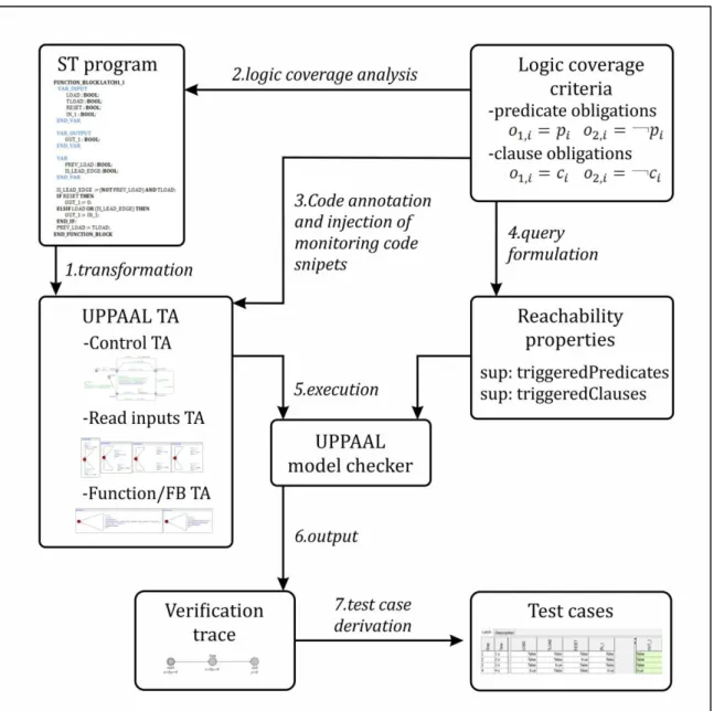
In this research we addressed the problem of test case generation for the Structured Text (ST) programming language from the IEC 61131-3 PLC standard. ST is a non-executable programming language with a standardization purpose for the runtime PLC programming languages. Therefore, it needs to be formalized before the test case generation. For that purpose we used UPPAAL model checker because of its analogy with certain elements in ST language and the possibility of deriving test cases for achieving maximum logic coverage. Although UPPAAL model checker is not specifically intended for the purpose of test case generation we overcome this constraint by conducting the transformation defined in this research. In order to achieve maximum logic coverage we use a defined annotation concept for targeted logic elements (clauses and predicates). We also showed how to implement a tool-supported approach suitable for industrial adoption. With that in mind we also conducted test generation results and performance analysis, comparing them with results provided in similar research for IEC 61131-3 FBD programming language. The results in this thesis show performance improvements in terms of generation time and memory consumption when using this novel transformation. With the approach defined in this thesis, test generation for certain type of FBD programs, which are translatable to ST, could be improved in terms of efficiency of generating these tests. Finally, we provided the answer to the question of what is the achievable formalization level from ST to UPPAL model checker.
Contents
Abstract ... 2
1. Introduction ... 6
1.1 Problem formulation ... 7
1.2 Approach and results ... 8
2. Background ... 9
2.1 Programming logic controller ... 9
2.2 State of the art ... 11
2.3 Language specifications ... 12
2.3.1 Structured Text ... 12
Elements inherited from the standard ... 12
Variables ... 17
Variable sections ... 17
Standard functions ... 18
Standard function blocks ... 18
Specifically ST elements ... 19
2.3.2 UPPAAL ... 22
Timed automata ... 22
UPPAAL extension for Timed Automata ... 24
Transition defining elements... 25
C language subset ... 26
Operators ... 28
2.4 Testing and logic coverage... 31
3. Method ... 33
4. Technical design ... 34
4.1 Overview of ST-UPPAAL transformation and test case generation ... 34
4.1.1 ST code example ... 35
4.2 Global picture of the transformed model ... 36
4.3 Control template ... 37
4.4 Read inputs templates ... 41
4.5 Function/FB templates ... 43
4.6 Global declarations ... 45
4.6.1 Variable declarations ... 49
Limitations ... 49
4.7 Function C subset implementation ... 50
4.7.1 Local variables implementation ... 52
4.7.2 Behavior transformation ... 53
Keywords, operators and statements transformation ... 53
4.8. Logic coverage analysis ... 60
4.8.1 Predicate annotation and monitoring ... 60
4.8.2 Clause annotation and monitoring ... 63
4.8.3 Reachability property ... 64
4.9 Test case generation ... 66
5. Results and evaluation ... 68
5.1 Experimental comparison ... 71
5.2 Related work discussion ... 76
6. Conclusion ... 78
List of figures
1.1: FBD diagram with ST expansion...………7
2.1: PLC structure...………...9
2.2: PLC hardware based structure ..………...9
2.3: Possible invocations between function (F), function block (FB) and Program ...……….13
2.4: Timed automata example………23
2.5: Formal definition of C subset declarations ..…..………...26
2.6: Formal definition of C subset statements ..………27
3.1: Research process………...32
4.1: Transformation diagram ..……….33
4.2: ST code example 1……….34
4.3: Overview of the UPPAAL model .……….35
4.4: Control template .……….………37
4.5: Input assignment process of the control template....……….38
4.6: Execution of functions and FBs behavior ...……….38
4.7: UpdateOutputs KeepInputs transition ...………..……….…39
4.8: Automata stop and continuation ...………..40
4.9: Read boolean-type template...……….40
4.10: Read inputs templates from ST Example 1 ...………..………..41
4.11: Boolean-type read template, definition ...…...……….41
4.12: Integer-type read template, definition …….…….………..42
4.13: Functions from the ST example 1………..………43
4.14: Behavior function definition ..………...………..43
4.15: Logic coverage function definition………..……….44
4.16: Global declarations of ST example 1………..……….46
4.17: Initialization of the ST example 1 ...………..………...49
4.18: Initialization definition………...………..49
4.19: Update outputs function of ST example 1...………..………50
4.20: Update label of the function1 (from ST example 1) .………….………50
4.21: Update label of the function1 (from ST example 1) ……….………..50
4.22: Local variables declaration section (in Function Blocks) .….………..51
4.23: Local variables declaration section (in Functions) ..……….………51
4.24: Behavior part of the ST example 1 ..………..……….52
4.25: Nested if statements (red – unwritten closed) ...………...……..…..………53
4.26: Transformation of case statements ..………..………..………55
4.27: ST FOR statement (x, y and z are integer values) .……….………..55
4.28: ST FOR transformation ..………...………..56
4.29: ST FOR transformation (increment/decrement construct)...…….……….56
4.30: Executable for statement ………..………...………..57
4.31: ST WHILE statement …...………...………57
4.32: ST WHILE transformation ...…..………57
4.33: ST REPEAT statement………..………..58
4.34: ST REPEAT transformation ..………..………..58
4.35: Example for boolean assignment monitoring ...….……….60
4.36: Definition of boolean assignment predicate annotation………60
4.37: Definition of IF statement’s predicate annotation ……….61
4.38: Definition of while statement predicate annotation ..………..62
4.39: Definition of clause annotation ...……….………63
4.40: ST example of clause annotation (code injection)………..63
4.41: Test case iteration in control template (ST example)………..65
4.42: UPPAAL diagnostic trace…….……….………..66
5.2: Test suite 2 for LATCH1_I……….……….68
5.3: Test suite 3 for LATCH1_I……….……….68
5.4: LATCH1_I logic elements annotation ...……….………..69
5.5: Fan_Control FBD program ……….………..70
5.6: Fan_Control ST program……….……...71
5.7: Fan_Control FBD test suite 1……….……..72
5.8: Fan_Control ST transformation test suite 1 ...………72
5.9: Fan_Control FBD test suite 2……….……..73
5.10: Fan_Control ST test suite 2 ...……….……..73
5.11: Fan_Control FBD test suite 3 ..……….……..74
5.12: Fan_Control FBD test suite 3 ……….…….…...74
List of tables
2.1: Elementary ST data types ...………..……….………142.2: Elementary ST data types with specifications ...………..………..15
2.3: N bits notes explanations………..…….……….16
2.4: Variable sections ………...………..…….………17
2.5: ST operators and their precedence…...19
2.6: ST formal definition………..………..……….21
2.7: C subset data types...………..………..………26
2.8: C subset operators....………..………..………28
2.9: Precedence order of C subset operators……….………...………...29
4.1: Transformation of operators ...…….……….………...…...…………54
5.1: Logic coverage analysis of Test suite 1...………..………...………...…………69
5.2 Performance analysis for breadth first SO with shortest trace ...……….…...….……….73
5.3 Performance analysis for depth first SO with trace set to some …...……….….………..74
5.4 Performance analysis for random depth first SO with trace set to some ……...….……...75
1. Introduction
IEC 61131-3 is an international standard that summarizes requirements of programming logic controllers (PLC). It is created by the International Electrotechnical Commission (IEC) [12]. The main goal of the standard is to provide consistency of integration, norms and reusability of PLCs. Before the standard was established different PLC manufacturers had difficulties in meeting these criteria. As soon as the IEC 61131-3 standard enabled the reusability of PLCs, the need for their verification and validation increased. It is commonly important to reach adequate level of risk in order to integrate PLC in certain fields.
All of the programming languages within the standard are not executable. In this research we are addressing Structured Text (ST). ST is a textual language which has the biggest level of expression among the languages from IEC 61131-3 standard [3]. It contains the logics and concepts which can be implemented with run-time PLC's programming languages [2]. Because of the issues stated before, it is recommendable to follow the implementation made in some of the standard's language. If it is done properly, the integration with other PLCs and its usage in different systems would be facilitated. Many programmers and companies implement their PLCs according to the abstract languages from the IEC 61131-3 standard. Therefore it is necessary to validate and verify them from the beginning of development. This is however not an easy task as they cannot be executed on the real hardware.
That is the reason why many researchers nowadays strive towards the formalization of those languages [3,4,5,6]. Transforming the standard's languages to a formal representation can benefit verification and validation of the program. The formalization process of the standard-implemented PLC program is also known as the reinterpretation/translation of the PLC program (from one source to another) [5].
In this survey paper [5] it is also mentioned that there are two main aims for formalization:
Verification and Validation, and Reverse Engineering
The interest for verification of safety, lifecycle and timing properties of PLC programs is increasing. Different methods are used in order to provide adequate verification. Among them are: static analysis, abstract interpretation, invariant generation and slicing. According to [5], the two most promising directions are: model checking and theorem proving. According to [24], model checking is a method for formal verification of finite-state systems. Therefore, many of the formalization researches strive to transform one of the standard's programming languages into the input code of some of the existing model checkers [7] (Uppaal, SVM, NuSMV and others). After that, a model checker can automatically generate test cases for the model that is analogical to the implementation. In this thesis we address test generations for logic coverage. Safety standards mandate logic coverage analysis when testing safety-critical software written in ST language.
1.1 Problem formulation
ST serves as the language abstraction which gives specific concepts and guidelines to the executable PLC programming languages. Therefore, we need to formalize it before being able to automatically generate test cases which will provide us with maximum logic coverage for specific ST codes.
Many research papers, that are proposing the formalization of IEC 1131-3 programing languages, mainly covered graphical languages like FBD and LD. The structure of the PLC program in many cases can be described with FBD. But as FBD has limits in its syntax (caused by its graphical nature), ST is sometimes needed in order to expand its expression [2] as shown in Figure 1.1.
Figure 1.1: FBD diagram with ST expansion
As shown in Figure 1.1, most of the code is written in FBD programming language. However, functional block called Norm is implemented in ST. A lot of research was done in order to enable formalization and maximum logic coverage in FBD, but if implemented code contains only one instance of ST then we need to find the way to formalize this language as well. Therefore, in this research we address the problem from the preceding case, shown in Figure 1.3, and similar ones. With that in mind we created rules for the formalization and automatic test generation of ST programming language. By pointing the maximum and not 100% logic coverage of tested programs, we mainly refer to the fact that 100% logic coverage is implementation dependent. We can easily create a program which will reach some absorbing logical state and will not be able to alter it by any given input. The logic that can't be reached shouldn't be taken into account because of this issue.
As stated before, automatic test generation and maximum logical coverage could be provided by model checkers [7]. In this case it means that we need to transform ST into the input code of a particular model checker (UPPAAL in this research). Other options would be to transform ST directly to some formal programming language (C [23]) and then create an algorithm for test case generation which can produce maximum logic coverage.
One of the main problems encountered during this process is the level of possible formalization, which depends on the targeted language. By conducting the transformation into the input model, used by model checkers, we encounter the problem
with ranges of different data types. Some model checkers cannot produce test cases for ranges of float numbers or even cannot produce models for complex mathematical algorithms because of the time consumption and slow performance in executing such a task. Some researchers also point the problems within ST programming language itself [8]. This could also affect the reachable level of the formalization.
According to [5], there are three levels of formalization:
Formalization of parts of the control program (algorithms) Formalization of the complete programs
Formalization of the whole control configurations
Based on this discussion, we have devised the following research questions which we will answer with this thesis:
-RQ1: What are the transformation rules needed for translating ST programs into UPPAAL input model?
-RQ1a: Can this transformed ST model be used, using UPPAAL model checker, to generate tests achieving logic coverage of the ST program?
-RQ2: What is the achievable level of formalization of ST language if we use UPPAL model checker for test case generation?
1.2 Approach and results
In this research we use UPPAAL [13] model checker as the targeted as the target tool for modeling and test case generation. UPPAAL is successfully used for the formalization and test case generation of FBD language from the IEC 61131-3 standard [15]. The defined transformation of ST language to UPPAAL model checker generates test cases which achieve maximum logic coverage of the tested ST codes. It also maintains execution order and rules described in the standard [13] and the runtime execution order of the derived transformation model in UPPAAL. Because of that we are able to track covered logic elements of the underlined ST code in each execution cycle. Syntax analogy between ST language and UPPAAL C language subset allows a straightforward annotation of the code with logical elements. By injecting side-effect free snippets of logic monitoring code, we are able to terminate model checker execution by using temporal properties. After this step we analyze the trace provided by UPPAAL and detect the instances of test case cycles. At the end we can derive test suite that satisfies maximum logic coverage of the underlined ST code. We also compared the performance of test suite generation proposed in this research with the one proposed in [15]. Although the research conducted in [15] addresses FBD language, ST and FBD share analogy. Moreover, any FBD diagram can be translated to the ST code [3]. Therefore, we transformed the same program written in both languages with the proposed transformation rules. This comparison primarily showed significant performance improvements in shortest test suite generation which achieves maximum logic coverage. Needed time for the test suite generation of ST code, with breadth first search order, is 0.052s, compared to 0.319s needed for the transformation of the FBD diagram. States stored in those two transformations are constant for each generation, and they are: 6000 stored states (ST test suite generation) compared to 41120 stored states (FBD test suite generation). This difference causes memory consumption improvements in the generation of the underlined ST code for certain search orders (breadth first and depth first).
2. Background
2.1 Programming logic controller
Programming logic controller (PLC) is a type of the microprocessor-based controller. It uses programmable memory in order to store instructions, data and implement various functions such as: logic, timing, counting, arithmetic and others [1]. With these features PLC controls the machines and the processes.
One of the most important properties of PLCs is a reusability. Certain basic controller can be used among different control systems. Consequences are visible in nowadays flexible and cost-effective control systems [1], even though they vary in purpose, complexity and some other properties.
PLCs are mainly optimized for control tasks and the industrial environment. In many other terms, they are quite similar to the computers [1]. Next to the industrial prerequisites such as resistance to: vibrations, temperature, humidity and other risk factors, PLCs share one more important characteristic. They all have an interfacing for inputs and outputs inside the controller (Figure 2.1).
Figure 2.1: PLC structure
There are two main perspectives for viewing and manipulating programmable logic controllers. First one is hardware-oriented, and the second one is software oriented. From hardware aspect, according to [1], PLC system is generally consisted of:
central processing unit (CPU), power supply unit,
programming device, memory unit,
input and output sections and communication interfaces.
PLC's software and hardware are highly analogical. The purpose of programming device is to provide specified program into the program and data memory unit which communicates with the processor (shown in Figure 2.2). Input sections are the places where CPU is provided with information from external devices. On the other side, output sections are the places where CPU provides the information to external devices [1]. Inputs could be derived from switches, different type of sensors (photoelectric cells, temperature sensors...). Outputs could be provided to motor starter coils, solenoid valves etc.
One of the main principles that must be met in PLC software is an easiness of programming and understanding of the programming language [1]. In the first years of the PLC history, different manufacturers used different languages, mainly manufacturer-dependent [2]. Because of that, reusability of PLCs in the industry was limited. This also caused the issue of development time and cost [2]. By the time it was clear that it is important to standardize PLC programming languages in order to enable better integration between PLCs of different manufacturers. Providing ready-made standardized software components also resolved issues of reusability, development time and the development cost. It is important to mention one more organization which revises and updates the standard - PLCopen. PLCopen is a manufacturer independent international organization for PLC programming harmonization. It is an organization which enabled the second revision of the IEC 61131-3 standard and it has several activities with the goal of striving towards the standard improvement [2]. It defined three different levels for programming systems certification. The second one considers reusability [2]. Therefore, the IEC 61131-3 standard was constituted. It primarily describes concepts and guidelines for creating PLC projects. It also could be seen as a guideline for PLC programming [2]. Each particular programming system can keep to the standard in a certain amount. This amount is evaluated through 3 possible levels: Base Level (BL), Reusability Level (RL) and Conformity Level (CL) [2]. Each of them certifies certain programming system and declares how it can be treated, reused or handled.
IEC 61131-3 standard consists of 5 programming languages: Structured Text (ST), Function Block Diagram (FBD), Ladder diagram (LD), Instruction List (IL) and Sequential function chart (SFC) [2]. Among them, ST and IL are the only textual programming languages, whilst the others are graphical ones.
The main building unit of IEC 61131-3 is a POU (Program Organization Unit). It could be seen as the smallest independent unit of the PLC software program [2]. There are three types of POU units: Function (FN), Program (PROG) and Function block (FB). Program is often referred as the main program. It is an initial place for the various variable initializations and contextual declaration [2]. All of them can be expressed with ST language (which is not the case for some others standard's programming languages). There are even assertions that equivalent code for ST can be derived from the code from any other IEC 61131-3 programming languages, but not vice versa [3]. However it is important to point that this is possible only in a certain abstract level when it comes to IL, as IL can directly manipulate physical memory unlike the ST. According to [2], ST's main purpose, among the other programming languages of the standard, is the representation of complex algorithms, mathematic calculations and control tasks.
Because of above mentioned facts and the fact that ST can express FBD or even enlarge its level of expression, ST is the main interest point of this research.
2.2 State of the art
There are several different techniques proposed in the recent researches which are used for the formalization/transformation of the IEC 61131-3 programming languages. We can classify them in the following categories:
XML-based transformations [4,9,10], compiler-based formalizations [3] ,
formal language transformations [6,8,11,23] and model-checking transformations [7, 15, 20]
PLCopen has a branch called TC6 which establishes an XML standard for all of the IEC 61131-3 programming languages. One of the main goals of these XML representations is re-engineering and visualization but also the formalization of the PLC programs. Those standard representations are mainly used for the formalization to the vendor-independent languages as stated in [10].
Compiler-based formalization, consists of creating a ST language compiler which produces universal code that afterwards could be executed on a different virtual and real machines. In the tool-approached research proposed by Rzonca et al. [3], they use a CPDev tool in order to generate code (from ST program) which afterwards can be executed on Java-like virtual machines. This approach uses compiler-based units such as: parser, scanner and code generator. However, this research does not cover the verification part of the ST programs.
Formal language transformation consists of direct transformation from ST programs to the programs written in some of the formal programming languages [8,23]). In the paper proposed by Kabra et al. [8], they create a translator from ST language to MISRA-C language. MISRA-C is a subset of C used in safety-critical applications. Although they do not address the automated test generation or some other verification possibilities, they addressed some of the standard’s issues [11]. In papers [6,23] formalization is made from ST to ANSI-C programming language. This language is usually used for the prototype systems [6]. In paper proposed by Sadolewski et al. [6] the formalization rules are proposed and later on adapted for the verification purposes in [23]. However in [23] the research does not cover test generation nor the concept of the logic coverage of the ST programs. It uses tool-supported approach for the verification of the compliance between specification and the code, which is performed by Coq tool [23].
Model checking transformation consists of defining set of rules which can simulate the execution of the ST program in one of the existing model checkers. In paper proposed by Gourcuff et al. [7] the main point was addressed to the analysis of the model-checking scalability for the NuSMV model-checker. They also propose the method for the translation of the ST language to NuSMV model. This method does not cover logic coverage analysis and test generation. The two most important related works with this thesis are papers of Ammann et al. [20] and Enoiu et al. [15]. Amman’s paper explore the role of model checkers in software testing and proposes general approaches for using model checkers in test generation evaluation. Based on this work, in the paper proposed by Enoiu et al. [15] they create an approach for the automated test case generation of programs written in FBD language using UPPAAL model checker. These two papers provided the main guidelines for the approach defined in this thesis.
2.3 Language specifications
The required transformation1/translation could be seen as a conceptualization of the mathematical function. In this transformation - ST is a domain and UPPAAL elements and language subsets represent the codomain of the function. Both of these entities represent the finite sets of building elements with certain levels of syntax and expression. Before doing the transformation it is necessary to analyze them both. By observing their building units, data types and constraints we can do the first selection of the possible transformations among those units.
2.3.1 Structured Text
Elements inherited from the standard
As stated before, the main building unit of the 61131-3 standardized PLC program is POU (Program Organization Unit) which could be presented in three following forms:
as a function,
a function block2, or a program
Function is a stateless POU type [12]. It does not store nor persist any state. Important properties of the functions are:
provides a result which could be an onedata element or a multivalued element -array/structure
can provide output variable (one or more) and they can be multi-valued elements as well
Function block (FB) is a type of POU which unlike functions has its own state. Its main purpose is to modularize and structure a straightforwardly defined portion of the program. It is analogical to the class-object manifestation in the OO programming. FB is existent in two forms - as a type and as an instance.
As a type, function block consists of:
the definition, which is structured of: input, output, internal variables, and
a set of operations which should be performed when the instance of the function block is called
From the instance perspective:
it is a multiple specifically named usage of a function block type, and
each instance should have an identifier associated with it, also it should have a data structure containing the static input, output and internal variables
Program is defined as a "logical assembly of all the programming language elements and constructs necessary for the intended signal processing required for the control of a machine or process by a PLC-system", by IEC 61131-3 standard [12].
1 In the following pages of the thesis, the formalization process from ST to UPPAAL model will be referred as a transformation, because UPPAAL is not a formal language but the model checker which contains a C language subset among many other concepts.
Figure 2.3: Possible invocations between function (F), function block (FB) and Program
As shown in Figure 2.3 we show what are the possible invocations between different POU types. Program can invoke functions and function blocks. Functions can only invoke functions, function blocks can invoke functions and function blocks.
In order to understand a declaration of these organization units we need to define and present common language elements of the ST programming language. PLC programs are made of many different basic language elements. These elements together create declarations and statements. Basic division of ST's language elements according to [1] addresses the following elements:
Delimiters Keywords Literals Identifiers
Delimiters are special characters with different meanings which make strict borders between different language elements. Delimiter examples in ST are the following characters: colon (‘:’), comma (‘,’), parentheses - ‘(’ and ‘)’, asterisk (*), equal (=), plus (+), minus (-) and semicolon (;).
Keywords represent the standard identifiers which belong to the word set of the programming language itself (ST in this case). Each keyword has the intended purpose and syntax which is clearly defined by IEC 61131-3 standard. User cannot override keywords for its own purpose. Standard is not case-sensitive when it comes to the keywords so "retain" and "RETAIN" is treated the same. Reserved keyword could represent:
name of elementary data type name of standard function name of standard function block
names of input and output parameters of standard function blocks name of input parameters of standard function
Some of the keywords in ST are the following elements: (RETAIN), (VAR_INPUT), (END_VAR) and (FUNCTION).
Literals are the value representations for different data types. Format of the literal depends on the data type of the variable. Data type further defines the possible value ranges. According to [1] there are three basic types of literals:
Numeric literal (numeric values for bit string numbers, integers and floating-point numbers)
Character string literals (character string values in single-byte or double byte representation)
Time literals (values for date, time and duration)
The examples of literals in ST are: (64, 4.943E-12, 16#0B) for a bit string numbers, ('this is a text') for a character strings, and (tod#12:16:28.44) for a time literal.
Identifiers are alphanumeric character strings for variable names, labels, POUs etc. specified by the PLC programmer. They must start with a letter or a single underline character followed by some amount of letters, digits and/or underline characters. Standard is not case sensitive and therefore an identifier "CIRCLE_ST" is regarded the same as "circle_ST". Identifiers can be assigned to different language elements, such as:
Jump and network labels Enumeration constraints
Configurations, resources, tasks/run-time programs Programs, functions, function blocks
Access paths
Variables (general, symbolic and directly represented variables) Derived data types, components of a structure
Transitions, steps, action blocks
Identifier examples are: (Var_2, Inp3), (EmergOff), (Real_Out) and (RealAdd).
Pragmas are the language structures used for automatic pre-processing and post-processing of the programs. The syntax and semantics of pragmas is implementation-dependent and therefore is not defined by standard. An example of pragmas is:
{Author M, Version 3}{m := 3}
Next to the above mentioned language elements it is important to address a set of possible data types in ST. Data type is a classification of each variable and literal [1]. It defines their possible values, operations that can be performed on them and the way the values are stored. According to standard [12], a set of pre-defined or elementary data types is specified. The main characteristic of elementary data types is their data width and their possible value range. Elementary data types are shown in Table 2.1.
Table 2.1: Elementary ST data types Boolean/
stringbit Signed integer Unsigned integer Floating point (Real) Time, date and character duration, string
BOOL INT UINT REAL TIME
BYTE SINT USINT LREAL DATE
WORD DINT UDINT TIME_OF_DAY
DWORD LINT ULINT DATE_AND_TIME
LWORD STRING
In Table 2.1, D stands for double, L for long, S for short and U for unsigned. The characteristics of elementary data types are not presented in this table. They are presented in Table 2.2. The most important characteristic in our case is a default value. The default value will be taken if the one is not provided within the initialization of the variable. Another provided information in this table is a number of bits required per
Table 2.2: Elementary ST data types with specifications
Description Keyword Default init value N
(bits)
Boolean BOOL 0,FALSE 1 h
Short integer SINT 0 8 c
Integer INT 0 16 c
Double Integer DINT 0 32 c
Long Integer LINT 0 64 c
Unsigned short
integer USINT 0 8 d
Unsigned integer UINT 0 16 d
Unsigned double
integer UDINT 0 32 d
Unsigned long
integer ULINT 0 64 d
Real number REAL 0.0 32 e
Long reals LREAL 0.0 64 f
Duration TIME T#0s -- b
Duration LTIME LTIME#0s 64 n
Date DATE Implementer specific -- b
Long Date LDATE LDATE#1970-01-01 64 n
Time of day TIME_OF_DAY/TOD TOD#00:00:00 -- b Time of day LTIME_OF_DAY/LTOD LTOD#00:00:00 64 o,q Date and time of Day DATE_AND_TIME or DT Implementer specific -- b Date and time of Day
LDATE_AND_TIME or
LDT LDT#1970-01-01-00:00:00 64 p,q Variable-length
single-byte
character string STRING '' (empty) 8 i,g,k,l
Variable-length double-byte
character string WSTRING "" (empty) 16 i,g,k,l Single-byte
character CHAR '$00' 8 g,l
Double-byte
character WCHAR "$0000" 16 g,l
Bit string of length 8 BYTE 16#00 8 j,g
Bit string of length
16 WORD 16#0000 16 j,g
Bit string of length
32 DWORD 16#0000_0000 32 j,g
Bit string of length
64 LWORD 16#0000_0000_0000_0000 64 j,g
Table 2.3 shows the notes from the N (bits) column entries in the Table 2.2. It is also derived from the standard [12].
Table 2.3: N bits notes explanations
Note Explanation
b
The range of values and precision of representation in these data types is Implementer specific
c
The range of values for variables of this data type is from - (2N-1) to (2N-1)-1.
d
The range of values for variables of this data type is from 0 to (2N)-1.
e
The range of values for variables of this data type shall be as defined in IEC 60559 for the basic single width floating-point format. Results of arithmetic instructions with denormalized values, infinity, or not-a-number values are Implementer specific.
f
The range of values for variables of this data type shall be as defined in IEC 60559 for the basic double width floating-point format. Results of arithmetic instructions with denormalized values, infinity, or not-a-number values are Implementer specific.
g A numeric range of values does not apply to this data type.
h
The possible values of variables of this data type shall be 0 and 1, corresponding to the keywords FALSE and TRUE, respectively.
i
The value of N indicates the number of bits/character for this data type.
j
The value of N indicates the number of bits in the bit string for this data type.
k
The maximum allowed length of STRING and WSTRING variables is Implementer specific.
l
The character encoding used for CHAR, STRING, WCHAR, and WSTRING is ISO/IEC 10646
m
The data type LTIME is a signed 64-bit integer with unit of nanoseconds.
n
The data type LDATE is a signed 64-bit integer with unit of nanoseconds with starting date 1970-01-01.
o
The data type LDT is a signed 64-bit integer with unit of nanoseconds with starting date 1970-01-01-00:00:00.
p
The data type LTOD is a signed 64-bit integer with unit of nanoseconds with starting time midnight with TOD#00:00:00.
q
The update accuracy of the values of this time format is Implementer specific, i.e. the value is given in nanoseconds, but it may be updated every microsecond or millisecond.
Next to the elementary data types, standard covers arrays and data structures as well. Arrays represent consecutive data elements of the same type in memory, while data structures represent programmable hierarchical structures derived from elementary or derived data types. With defined data types we can continue by defining variables.
Variables identify data objects whose content might change. Unlike the literals, value of the variable may change over time. They are declared inside specifically designated variable sections. According to the standard [12], variable can be declared using:
an elementary data type or a previously-defined type or a reference type or
an instantly user-defined type
A variable can be a single-element variable, a multi-element variable (ARRAY or a STRUCT) and a reference (a variable which refers to some other variable or function block instance).
Variable declaration includes:
name or a list of variable names which are declared a colon (":") and
a data type which can be followed with the variable initialization Example:
VAR myVar : INT; END_VAR
Variable sections are dedicated variable declaration segments which may be used in function blocks, functions or programs. Commonly, each POU consists of several variable sections. Variable sections not only distinguish and declare different types of variables, they also affect the access rights of each declared variable. According to the standard [12], Table 2.4 shows defined variable sections and their access rights:
Table 2.4: Variable sections
Keyword Usage
Access rights External Internal VAR Internal to entity (function, function block, program) NA RW VAR_INPUT Externally supplied, not modifiable within entity W R VAR_OUTPUT Supplied by entity to external entities R RW VAR_IN_OUT
Supplied by external entities, can be modified within entity and supplied to
external entity RW RW
VAR_EXTERNAL Supplied by configuration via VAR_GLOBAL RW RW
VAR_GLOBAL Global variable declaration RW RW
VAR_ACCESS Access path declaration RW RW
VAR_TEMP Temporary storage for variables in function blocks, methods and programs NA RW VAR_CONFIG Instance-specific initialization and location assignment - -
END_VAR Terminates various VAR sections above - -
In Table 2.4, R stands for read rights, W for write, RW for read and write rights and NA for not accessible. The external access rights are indicated for the calling (external) POU,
while the internal rights are indicated within the internal POU, where the declaration is made. The variable section keywords can be followed by the following qualifiers:
RETAIN (Retentive variables),
NON_RETAIN (Non-retentive variables),
PROTECTED (Accessible from inside the own entity and its derivations), PUBLIC (Accessible from all entities),
PRIVATE (Accessible from own entity),
INTERNAL (Accessible from the same namespace) and CONSTANT (variables cannot be modified).
By this, we covered the most important ST language elements and properties which will be mentioned in the research. However, IEC standardized some of the basic functionalities (POUs) as well. Standardized PLC functionality could be observed through standard functions and standard function blocks
Standard functions represent basic logical operators (bit-shifting, addition, comparison etc.). As previously mentioned in POU section, they are stateless. The IEC 61131-3 standard differentiates eight groups of standard functions:
Data type conversion functions, Numerical functions,
Arithmetic functions, Bit-string functions,
Selection and comparison functions, Character string functions,
Functions for time data types and Functions for enumerated data types
Standard function blocks represent PLC functions with status or a state information. Typical representatives of the standard function blocks are timers, counters etc. The IEC 61131-3 standard differentiates five groups of standard function blocks:
Bistable elements or flip flops Edge detection
Counters Timers
Communication function blocks
The aim of this chapter is to compare the structure of ST and UPPAAL. It also tends to point basic ST elements and building blocks in PLC systems.
Specifically ST elements
ST expressions are constructs which return a value of some data type after the evaluation. Expressions consist of operators and operands. Operand could be a variable, a literal, enumerated value, function call with a result, FB call instance with a result or another expression. According to the standard [12], there are several rules for the evaluation of expressions:
1. Operands are applied by the operators in a predefined sequence known as operator precedence (shown in the Table 2.5).
2. Equal precedence operators are applied from left to right as written in the expression.
3. If an operator has two operands then the leftmost one should be evaluated first. 4. Boolean expressions may be evaluated to the extent necessary to deliver the final
value of the expression.
Example: (A<B) & (C>D) could be evaluated only until (A<B) evaluates to FALSE 5. Functions and methods may be called within the expression as its elements. In
this case they are called in a form of the function name followed by the parenthesis with parameters.
6. If the operator in an expression could be represented as one of the overloaded functions, conversion of operands and results shall follow the rules and examples given above.
ST operators are constructs which behave like functions but generally have a different syntax or even semantics than the general functions. Table 2.5 shows all of the ST operators.
Table 2.5: ST operators and their precedence
Syntax Description Precedence
() Parenthesis alter the evaluation order 11(Highest) Identifier
(parameter list)
Evaluation of result of function and method
-if a result is declared 10
^ Dereference 9 - Negation 8 + Unary plus 8 NOT Complement 8 ** Exponentiation 7 * Multiply 6 / Divide 6 MOD Modulo 6 + Add 5 - Subtract 5 <,>,<=,>= Comparison 4 = Equality 4 <> Inequality 4 & Boolean AND 3
AND Boolean AND 3
XOR Boolean Exclusive OR 2
ST statements are instructions that should perform a specified action by some of the executable programming languages. In the most used programming languages, it can be one of three different types: assignment, selection and iteration statement.
Assignment statement is used for the replacement of the current value of the single or multi-element variable. The new value can be a result of the expression evaluation. Example: A := B
Comparison statement returns a Boolean value. They are mainly consisting of a variable reference on the left side, followed by the comparison operator and a variable reference on the right side. This statement is of high importance in this research as its structure is very similar to the conditions and can affect condition coverage at the end. Selection statements select one or a group of its component statements for execution according to the specified condition. Selection statements can be IF and CASE.
Iteration statements specify the repetitive execution of the associated statements. Iteration statements can be WHILE, REPEAT, EXIT, CONTINUE and FOR.
Table 2.6: ST formal definition
Element Definition
Expression : Xor_Expr ( 'OR' Xor_Expr )*; Constant_Expr
:Expression; // a constant expression must evaluate to a constant value at compile time
Xor_Expr : And_Expr ( 'XOR' And_Expr )*;
And_Expr : Compare_Expr ( ( '&' | 'AND' ) Compare_Expr )*; Compare_Expr : ( Equ_Expr ( ( '=' | '<>' ) Equ_Expr )* );
Equ_Expr : Add_Expr ( ( '<' | '>' | '<=' | '>=' ) Add_Expr )*; Add_Expr : Term ( ( '+' | '-' ) Term )*;
Term : Power_Expr ( '*' | '/' | 'MOD' Power_Expr )*; Power_Expr : Unary_Expr ( '**' Unary_Expr )*;
Unary_Expr : '-' | '+' | 'NOT' ? Primary_Expr; Primary_Expr
: Constant | Enum_Value | Variable_Access | Func_Call | Ref_Value| '(' Expression ')';
Variable_Access : Variable Multibit_Part_Access ?;
Multibit_Part_Access : '.' ( Unsigned_Int | '%' ( 'X' | 'B' | 'W' | 'D' | 'L' ) ? Unsigned_Int ); Func_Call : Func_Access '(' ( Param_Assign ( ',' Param_Assign )* )? ')'; Stmt_List : ( Stmt ? ';' )*;
Stmt
: Assign_Stmt | Subprog_Ctrl_Stmt | Selection_Stmt | Iteration_Stmt;
Assign_Stmt : ( Variable ':=' Expression ) | Ref_Assign | Assignment_Attempt; Assignment_Attempt
: ( Ref_Name | Ref_Deref ) '?=' ( Ref_Name | Ref_Deref | Ref_Value );
Invocation
: ( FB_Instance_Name | Method_Name | 'THIS'
| ( ( 'THIS' '.' )? ( ( ( FB_Instance_Name | Class_Instance_Name ) '.' )+ ) Method_Name ) )
'(' ( Param_Assign ( ',' Param_Assign )* )? ')'; Subprog_Ctrl_Stmt : Func_Call | Invocation | 'SUPER' '(' ')' | 'RETURN'; Param_Assign
: ( ( Variable_Name ':=' )? Expression ) | Ref_Assign | ( 'NOT' ? Variable_Name '=>' Variable );
Selection_Stmt : IF_Stmt | Case_Stmt;
IF_Stmt
: 'IF' Expression 'THEN' Stmt_List ( 'ELSIF' Expression 'THEN' Stmt_List )* ( 'ELSE' Stmt_List )?
'END_IF'; Case_Stmt
: 'CASE' Expression 'OF' Case_Selection + ( 'ELSE' Stmt_List )? 'END_CASE';
Case_Selection : Case_List ':' Stmt_List;
Case_List : Case_List_Elem ( ',' Case_List_Elem )*; Case_List_Elem : Subrange | Constant_Expr;
Iteration_Stmt : For_Stmt | While_Stmt | Repeat_Stmt | 'EXIT' | 'CONTINUE'; For_Stmt : 'FOR' Control_Variable ':=' For_List 'DO' Stmt_List 'END_FOR'; Control_Variable : Identifier;
For_List : Expression 'TO' Expression ( 'BY' Expression )?; While_Stmt : 'WHILE' Expression 'DO' Stmt_List 'END_WHILE'; Repeat_Stmt : 'REPEAT' Stmt_List 'UNTIL' Expression 'END_REPEAT';
2.3.2 UPPAAL
UPPAAL is a model checking, verification toolbox for the real-time systems [13]. It is developed by Uppsala University and Aalborg University. Since then it was successfully applied in various case studies. The main concept used in UPPAAL is a verification of systems that can be modeled as a network of timed automata. According to [5,24], model checking is a method for formal verification of finite-state systems. It consists of two main concepts [20]:
A model, which is a state machine described with variables, initial values and conditions under which variables may change values.
Temporal logic constraints, which is a stopping criteria for the verification. Model checker visits all reachable states in order to verify that temporal logic is satisfied.
Timed automata
Timed automata (TA) is a theoretical paradigm for modeling and verification of real time systems. It is important to mention that timed automata, according to [14] is a general term that describes a finite state Büchi automation which is extended with a set of real-valued variables and modeling clocks. More specific and simplified version called Timed Safety Automata is used in UPPAAL model checker and this one will be briefly described in this section.
A timed finite automata consists of finite set of nodes (locations) and finite set of labeled edges. In general type of timed automata, automata is extended with real-valued variables but in UPPAAL it is extended with integer variables. This kind of automata represents an abstract model of a timed system. Variables represent the logical clocks in the system. When the system is started variables are initialized with zero values and afterwards they may increase synchronously with the same amount. The behavior of the automata is constrained and controlled by guards i.e. clock constraints which could be defined for edges in the automata. Some edge could be taken only if the clock values satisfy the guard which is labeled to that edge (transition).
Formal syntax of timed automata according to [13,14,18] consists of: - a set of clocks
- a set of conjunctions over simple conditions of the form or , where and .
- a set of locations
- initial location, where
- a set of actions, co-actions and the internal - action
- a set of edges between locations with an action, a guard and a set of clocks to be reset
- assigns invariants to the locations
Therefore the timed automata A is a tuple ( ) where: - L is a finite set of locations (nodes),
- is the initial location
- is a set of edges and - assigns invariants to locations
Semantics of TA is defined as follows. Let ( ) be a timed automata, semantics is defined as a labeled transition system , where:
- is the set of states, - is the initial state and
- is the transition relation
Figure 2.4: Timed automata example
In Figure 2.4, we show a more concrete example of timed automata. A set of clocks in this automata consists of two clocks (x and y). A set of locations consists of start, loop and end location. Initial location is start and it is indicated by two concentric circles. A set of conjunctions over clocks in this example includes the following:
A set of actions consists of work, leave and enter action. In the example, shown in Figure 2.4, there are no invariants. Figure 2.4 shows one specific timed automata, however UPPAAL mostly uses models which represent network of timed automata [19]. As a continuation of the previous definition of timed automata (A) we will define the network according to [13] which states following:
Let be a network of timed automata3 and let be an initial location vector. The semantics of TA network is defined as a transition system , where:
- is the set of states, - is the initial state and
- is the transition relation.
Transition relation in the network of timed automata is different than the relation in TA. It is expanded with synchronization functions (i.e., a! is correlative with a?) [15]. These functions are responsible for communication between different timed automata. For more information about TA refer to [13,14,15,18].
UPPAAL extension for Timed Automata
Next to the previously defined elements and terms, UPPAAL modeling language extends Timed Automata with the following ones [13].
Templates are automata segments defined with locations and edges. Template can also have a set of parameters that can be of any supported data type (defined below). Templates are instantiated by a process assignment which is defined in the system definition.
Constants are non-modifiable integer values in this case. They are declared with const keyword. Example:
const variable_name value.
Bounded integer variables defines an integer range variable in UPPAAL. It can be declared as int[min,max] variable_name, where min represents lower and max represents an upper bound. Bounded integer variables can be used in guards, invariants and assignments (special UPPAAL expressions which will be describe later on).
Binary synchronization channels are used for the synchronization between different edges. They can be declared with chan c notation. Edge labeled with c! synchronizes with another edge labeled c? .
Broadcast channels similarly as in previous case are used for edge synchronizations. In this case however a sender c! can synchronize with arbitrary number of receivers c?. Declaration for this type is made with the following notion- broadcast chan variable_name.
Urgent synchronization defines the situations when delays must not occur if a synchronization on an urgent channel is enabled. Edges that uses urgent synchronization cannot have time constraints (clock guards).
Urgent location is the equivalent to the location which has an extra clock x which is reset on all of the incoming edges and has an invariant x<=0. This means that time is not allowed to pass in an urgent location.
Committed locations are acting even more restrictively than the urgent location. A state is committed if any of the locations in that state is committed. This committed state cannot delay and demands the next transition on an outgoing edge of any of the committed locations.
Arrays are same as in ST, and they are allowed for clocks, channels, constants and integer variables. Example of the array declaration is as follows: clock a[2];
Initialisers are used for the initialization of the integer variables or arrays of integers. Example of the initialiser in both cases respectively is:
int i = 2;
Record types are similar to the data structures in ST when used in custom type creation and they are declared with the same keyword - struct. In the bellow written example the record (s) consists of two fields a and b:
struct {int a; int b;} s;
Custom types are defined with the typedef construct and can be defined with any other elementary type such as record.
User functions can be defined globally or locally (assigned to the template). Template parameters are accessible from the local functions. In UPPAAL, they are a part of the C subset language which will be described in the following sections.
Next to these elements, it is of importance to mention five more, which are crucial for the creation of TA with UPAAL. Each transition (branch) in UPPAAL can be defined and labeled with one of the expression types defined in the following Section.
Transition defining elements
Select label contains list of name : type expressions where name is a variable and type is a defined data type. These variables are accessible on the edges for which they are associated and they will take a non-deterministic value in the range of their defined types.
Guard is a specific type of an expression that must evaluate to a boolean value and must be side-effect free. A guard also can call a side-effect function that evaluates to the boolean value.
Synchronization label can be one of three possible forms: Expression!, Expression? or empty label. Expression must be free of any side-effect. It must evaluate to a channel and can only refer to integers, constants and channels.
Update label is a list of expressions which have side-effects. It can only refer to the integer variables, constants, and only assign integer values to a clocks. It also can call a function.
Invariant is an expression that satisfies the side-effect free condition. It also satisfies the conditions of possible restrictive usage of clocks, integer variables and constants only. It is a conjunction of the conditions which follow the form: or where is a clock reference and evaluates to an integer. Invariant can call a side-effect free function which evaluates to the boolean value, but a clock constraint is not supported in such a function.
UPPAAL model checker has another feature which is mainly addressing functions mentioned in some of the preceding elements (user functions). Those functions, as well
as the global and local declarations are written in a C language subset 4 provided by UPPAAL. The following content will define its elements and features.
C language subset5
Declarations in a C subset can be global or local. Declarable data types are: clocks, bounded integers, channels, arrays, records and types. Grammar definition of the declaration is shown in Figure 2.5.
Figure 2.5: Formal definition of C subset declarations
Data Types can be int (integer values), bool (boolean), chan (channel) and clock. Array and record types can be defined using these types and other user defined types.
Table 2.7: C subset data types
Description Keyword Value range
Boolean BOOL False or true
Integer INT [-32768, 32767]
Channel CHAN Urgent, broadcast or binary
Clock CLOCK No info6
Boolean type can have one of two possible values - true or false. It also can be presented in the numerical form and in that case false is 0 and true is any non-zero value.
Integer data type can take a value from the range in the table. Any value out of the predefined range will cause a verification to abort.
Channels can be declared as urgent or broadcast. If those two words are omitted than it is a binary channel.
Clocks can take only integer values.
System definition provides a definition of the system model. The model consists of: one or more concurrent processes (templates), local and global variables, functions and
4 UPPAAL C subset is defined in the help section of the UPPAAL toolkit and on the official UPPAAL web page: http://www.uppaal.com/index.php?sida=217&rubrik=101
5 Data for the C subset is extracted from the official UPPAAL web page: http://www.uppaal.com/index.php?sida=217&rubrik=101
6 This information is not provided, however clocks are referring to integer values, so the Declarations ::= (VariableDecl | TypeDecl | Function | ChanPriority)*
VariableDecl ::= Type VariableID (',' VariableID)* ';' VariableID ::= ID ArrayDecl* [ '=' Initialiser ]
Initialiser ::= Expression
| '{' Initialiser (',' Initialiser)* '}'
channels. Templates without parameters are translated into exactly one process. If the template is parameterized, then the process is created for each set of the parameter combinations.
Scalars are integer-like elements with a limited number of operations. It means that scalars are unordered (model cannot distinguish between different orders). This feature at the end results in a faster verification and less memory being used.
Functions can be global or locally assigned to the template. Their grammar definition is: Function ::= Type ID '(' Parameters ')' Block
As a continuation of the grammar for the function, other statements are defined in Figure 2.6.
Figure 2.6: Formal definition of C subset statements
Iterators, in C subset, are used with keyword for. However, for could be used in two different ways - like a C for loop and like a Java iterator.
C like for loop:
ForLoop ::= 'for' '(' Variable Init ';' Condition ';' Variable Update ')' Statement Java like iterator
Iteration ::= 'for' '(' ID ':' Type ')' Statement
Iterator will execute the Statement once for each value in ID of the type Type (can be array or a scalar).
Block ::= '{' Declarations Statement* '}' Statement ::= Block | ';' | Expression ';' | ForLoop | Iteration | WhileLoop | DoWhileLoop | IfStatement | ReturnStatement
ForLoop ::= 'for' '(' Expression ';' Expression ';' Expression ')' Statement Iteration ::= 'for' '(' ID ':' Type ')' Statement
WhileLoop ::= 'while' '(' Expression ')' Statement DoWhile ::= 'do' Statement 'while' '(' Expression ')' ';'
IfStatment ::= 'if' '(' Expression ')' Statement [ 'else' Statement ] ReturnStatement ::= 'return' [ Expression ] ';'
Operators are constructs which behave like functions but generally have a different syntax or even semantics than the general functions. Table 2.8 contains all of the C subset operators.
Table 2.8: C subset operators
Syntax Description
() Parenthesis alter the evaluation order [] Array lookup
. Infix lookup operator to access process scope ! Logical negation
++ Increment (can be used as both prefix and postfix operator) -- Decrement (can be used as both prefix and --> --postfix operator) - Integer subtraction (can also be used as unary negation)
+ Integer addition
<= Less than or equal to == Equality operator != Inequality operator >= Greater than or equal to > Greater than
& Bitwise and ^ Bitwise xor | Bitwise or
* Integer multiplication / Integer division
% Modulo
<< Left bit shift >> Right bit shift <? Minimum >? Maximum < Less than
&& Logical and || Logical or
?: If-then-else operator not Logical negation and Logical and or Logical or
imply Logical implication forall Forall quantifier exists Exists quantifier
Table 2.9: Precedence order of C subset operators Associativity Operators left () [] . (Highest)7 right ! ++ -- unary - left * / % left - + left << >> left <? >? left < <= >= > left == != left & left ^ left | left && left || right ?: right = := += -= *= /= %= &= |= <<= >>= ^= right not left and left or imply
left forall exists (Lowest)
Reserved keywords as in ST are already assigned for the functionalities provided by language and cannot be used as identifiers. UPPAAL has the following keywords: chan, clock, bool, int,commit, const, urgent, broadcast, init, process, state, guard, sync, assig n, system, trans, deadlock, and, or, not, imply,true, false, for, forall, exists, while, do, if, else, r eturn, typedef, struct, rate, before_update, after_update, meta,priority, progress, scalar, sele ct, void, default. The following words are reserved for the future updates: switch, case, continue, and break.
2.4 Testing and logic coverage
Software testing, in one of its many definitions, is defined as: "a process, or a series of processes which are designed to make sure that a computer code does what it was designed to do and, conversely, that it does not do anything unintended"[17]. In order to achieve the proper accuracy of such claims there are several different approaches and test requirements. Different perspectives in the software artifacts are used as the criteria for the testing. However, in all of them the most fundamental testing unit is a test case. Test case is composed of several elements:
test case values expected results prefix values and postfix values
Mostly all of them are necessary for a complete execution and evaluation of the tested software[16]. Test case values are input values which are necessary for a complete execution of the tested software. Expected result is a result produced by the test execution only in the case the program satisfies its behavior. Prefix value represents any input value that is needed in order to set the software into the appropriate state so it can receive test case values [16]. Postfix values represent input values that needs to be sent to the software after the test case values are sent [16].
According to [16], "Test requirement is a specific element of a software artifact that a test case must satisfy or cover". In order to systematically generate test requirements we also define coverage criterion. It represents a rule or set of rules that binds a test requirement with a test case.
If we declare a set of test requirements as TR for a coverage criterion C, then we state that test set T satisfies C if and only if for every test requirement tr in TR, at least one test t in T exists such that t satisfies tr [16]. If we want to measure coverage C and present it as a value we define it as a ratio between test requirements satisfied by the test case (T) and the size of test requirements TR. This value is called coverage level. In order to make the theory more specified we will explain logic coverage.
Logic coverage is a branch of software testing which tests criteria based on logical expressions in the code. Logical coverage is defined with its two main units - predicate and clause. A predicate is an expression which evaluates to a boolean value. It is important to mention that predicate is a topmost structure. If we occur the following expression: we can derive several expressions that may evaluate to a boolean value. However, the whole expression represents a predicate. Predicate may contain: function calls (that evaluate to a boolean value), boolean variables and values and finally non-boolean variables or values which are compared with comparator operators. Comparator operators are { }8. Internal structure of the predicate also consists of logical operators {conjunction , disjunction ,
8 Comparator operators between ST and UPPAAL language subset are almost the same. The difference is observable in inequality. Unlike the mathematical operators { } they both use {<=,>=} instead. For the inequality operator ST uses ' ' while C subset uses '! '. For equality operator ST uses ' ' and C subset uses ' '.


![Table 2.9: Precedence order of C subset operators Associativity Operators left () []](https://thumb-eu.123doks.com/thumbv2/5dokorg/4822561.129937/30.892.166.729.179.629/table-precedence-order-subset-operators-associativity-operators-left.webp)