2012:53
Technical Note
Review of Engineering Geology and Rock
Engineering aspects of the operation
and closure of a KBS-3 repository at
the Forsmark site – Initial Review Phase
SSM perspektiv
BakgrundStrålsäkerhetsmyndigheten (SSM) granskar Svensk Kärnbränslehantering
AB:s (SKB) ansökningar enligt lagen (1984:3) om kärnteknisk verksamhet om
uppförande, innehav och drift av ett slutförvar för använt kärnbränsle och
av en inkapslingsanläggning. Som en del i granskningen ger SSM konsulter
uppdrag för att inhämta information i avgränsade frågor. I SSM:s Technical
Note-serie rapporteras resultaten från dessa konsultuppdrag.
Projektets syfte
Uppdraget är en del i SSM:s granskning av aspekter inom Ingenjörsgeologi
och Bergteknik i SKB:s ansökan om slutförvaring för använt kärnbränsle i
Forsmark. Uppdraget avser granskning av integriteten för bergmassan som
omger ett slutförvar av KBS-3-typ med fokus på driften av anläggningen,
stabiliteten av bergrummen, underhåll, testning och degraderingskontroller
på konstruktioner och bergförstärkningar samt bergmekaniska
övervaknings-program. Förväntade risker under uppförande, driftskede och förslutning som
kan äventyra driftsäkerheten, integriteten för ingenjörsmässiga och naturliga
barriärer, kärnbränsledeponering samt säkerheten efter förslutning diskuteras.
Författarens sammanfattning
SRK Consulting (UK) Limited (SRK) har granskat frågor rörande
Ingenjörs-geologi och Bergteknik inom driften samt förslutningen av ett KBS-3
slutför-var i Forsmark. Granskningsuppdraget ingår i Strålsäkerhetsmyndighetens
inledande granskningsfas. Granskningen genomfördes av Dr David Saiang,
varav åsikterna i denna rapport kan vara personliga och inte nödvändigtvis
SRK:s åsikter.
Generellt är granskaren nöjd med SKB:s redovisning rörande
Ingenjörsgeo-logi och Bergteknik i slutförvaret. Det finns vissa frågor, till exempel bergets
respons på utschaktning, som inte kan hanteras helt förrän uppförandet har
inletts. SKB har anammat begränsningen och tydligt redovisat planer för
ve-rifiering och validering av lösningar för att öka förtroende för redovisningen
av slutförvarets strålsäkerhet.
Med utgångspunkt från platsspecifik geologi i Forsmark har SKB utvecklat
en Platsbeskrivande modell (SDM) som utgör grunden för all bergteknisk
projektering. SDM:s omfattning är multidisciplinär i och med att den mottar
bidrag från geologi, hydrogeologi, bergmekanik samt andra ämnesområden
inom geosfären. Emellertid finns det vissa osäkerheter som till exempel det
initiala bergspänningstillståndet där det är svårt att uppskatta
bergspänning-ar på grund av bergmassans komplexitet samt begränsningbergspänning-ar i mätmetoder.
SKB har försökt uppskatta konsekvensen av dessa osäkerheter för
uppföran-det av slutförvaret.
Under driften är målet att deponera minst en kapsel om dagen. Detta ställer
höga krav på processtyrning av synkroniserade aktiviteter från uppförande
av deponeringstunnlar och -hål till återfyllning. Dessa aktiviteter är
plane-rade att pågå samtidigt i olika delar av slutförvaret, därför bör känsligheten
för ömsesidigt inflytande observeras och följas upp. Till exempel har
han-teringen av återfyllnad identifierats som en flaskhals för driften och förslag
till förebyggande åtgärder uppgetts. Ett annat område som kan utvecklas
ytterligare är acceptanskriterier för deponeringshål (Extended Full Perimeter
Criteria). Påverkan från sprängning i form av vibrationer samt bergskador på
driften samt slutförvarets funktioner bedöms av SKB som acceptabla baserat
på genomförda studier.
Återfyllnad samt förslutning syftar till att innesluta slutförvaret och
be-handlar placering av återfyllnadsmaterial och betongpluggar. SKB har tagit
fram en uppsättning av kriterier för val, produktion samt installation av
återfyllning och förslutning. Förmågan hos återfyllnadsmaterial och dess
komponenter att uppfylla sin funktion med olika tekniska förutsättningar
och utvecklingsscenarier (kemiska och fysiska) har studerats. Slutförvaret
har också uppdelats i en ”övre” och en ”djup” del där olika återfyllnads- eller
förslutningskrav gäller.
Slutförvarslayouten behöver anpassas till huvudriktningarna för
bergspän-ningsfältet. Förvarsdjupet har valts baserat på en sammanvägning av
berg-massans kvalitet, geologiska och hydrogeologiska förhållanden.
Bergspän-ningarna kommer att ha en stor påverkan på utvecklingen av bergutrymmen
samt långsiktig säkerhet för slutförvaret. Därför bör bergspänningarna vara
kända med tillräckligt hög tilltro.
Skador som inträffar i berget på grund av spänningskoncentrationer eller
ut-schaktningsteknik utgör en risk för slutförvaret. SKB har studerat båda fallen
och är förvissad om att skadorna kommer att hållas till ett minimum och
un-der de kravnivåer som gäller för den långsiktiga säkerheten för slutförvaret.
Emellertid kommer det att behövas studier för att verifiera kravuppfyllelsen
samt förbättra utschaktningstekniken. SKB påstår att
projekteringsförutsätt-ningarna kommer att förbättras allt eftersom ny information blir tillgänglig
under slutförvarets uppförande.
SRK har identifierad några få områden där det antingen finns bristfällig
information eller utrymme för förbättringar. Dessa hör till de ovan
presente-rade områdena och i synnerhet gäller det bergspänningstillståndet,
ut-schaktningsteknik samt återfyllnadsmetoder. Sammanfattningsvis tycker SRK
att SKB:s angreppsätt är välutvecklat. Med hänsyn till slutförvarets enskilda
egenskaper kommer vissa frågor att kvarstå, så som hur osäkerheterna
påver-kar den långsiktiga säkerheten, och bara tiden kommer att utvisa svaret.
Projektinformation
Kontaktperson på SSM: Flavio Lanaro
Diarienummer ramavtal: SSM2011-3634
Diarienummer avrop: SSM2012-145
Aktivitetsnummer: 3030007-4018
SSM perspective
BackgroundThe Swedish Radiation Safety Authority (SSM) reviews the Swedish
Nu-clear Fuel Company’s (SKB) applications under the Act on NuNu-clear
Acti-vities (SFS 1984:3) for the construction and operation of a repository for
spent nuclear fuel and for an encapsulation facility. As part of the review,
SSM commissions consultants to carry out work in order to obtain
in-formation on specific issues. The results from the consultants’ tasks are
reported in SSM’s Technical Note series.
Objectives of the project
This project is part of SSM’s review of SKB’s license application for final
disposal of spent nuclear fuel at Forsmark and covers issues of Engineering
Geology and Rock Engineering. The assignment concerns review of the
integrity of the rock mass surrounding a KBS-3 repository with focus on the
operation and closure of the repository, stability of the excavations,
mainte-nance, testing and control of aging of the constructions and rock
reinforce-ments, and Rock Mechanics monitoring programmes. Foreseen risks during
the cycle of construction, operation and closure that can jeopardize
opera-tional safety, integrity of the engineered and natural barriers, deposition of
the waste and/or the closure of the repository are also highlighted.
Summary by the author
SRK Consulting (UK) Limited (SRK) has reviewed the Engineering
Geolo-gy and Rock Engineering aspects of the operation and closure of a KBS-3
repository at the Forsmark site in Sweden. The review assignment is part
of a Swedish Radiation Safety Authority (SSM) Initial Review Phase. The
review was carried out by David Saiang (PhD) on behalf of SRK. Therefore
some of the views expressed in the review report may not totally represent
those of the company (SRK).
In general SRK is satisfied with the efforts of SKB in dealing with the
engine-ering geology and rock engineengine-ering aspects of the repository. There are some
aspects, such as, the response of the rock due to the excavation, which
can-not be fully understood until the actual excavation is carried out. SKB has
accepted this limitation and has clearly indicated plans to verify and validate
these aspects to give greater confidence to overall safety of the repository.
With respect to the engineering geology of the Forsmark site, SKB has
deve-loped a Site Descriptive Model (SDM), which is the basis for all engineering
design in rocks, including a repository. The SDM developed by SKB is
cross-disciplinary, in that, it received inputs from geology, hydrogeology, rock
mechanics and other branches involved in geosphere science. Although,
there is some uncertainty in some aspects, such as the initial ground stress
conditions, it has never been easy to determine the ground stresses given the
complexity of the rock mass and the limitations of the many stress
measure-ment techniques available today. Nevertheless, SKB has attempted to address
the impacts of this uncertainty on the excavations.
ronised operations, from construction of the deposition cavities
(deposi-tions tunnels and holes) to backfilling of the cavities. These opera(deposi-tions are
planned to occur simultaneously and therefore the sensitivity of the
im-pact of one operation to another will be closely monitored and
synchro-nized. For example, the impact of backfilling procedures has been found
to be one bottle neck and methods to improve the procedures have been
recommended. Another area which can be further improved is the
rejec-tion/acceptance criteria EFPC (Extended Full Perimeter Criteria) for the
deposition holes. Impacts of blasting (vibrations and rock damage) to the
overall operation and performance of the repository are considered
ac-ceptable by SKB, concluding from the relevant studies it has carried out.
The sealing and closure aspects of the repository refer to the actual
isola-tion of the repository and deal with the aspects of backfilling and sealing.
SKB has a set of criteria or premises for selecting, manufacturing and
application of seal and backfill materials.
The ability of the backfill and seal materials and their components to
per-form in various engineered conditions and evolutionary processes (both
chemical and physical) have been investigated. The repository itself has
also been divided into upper and lower segments in order to define the
criteria for backfill and sealing requirements.
The excavation layout at Forsmark is clearly dependent on the orientation of
the ground stresses. The depth was selected based on the quality of the rock
mass and geological and hydrological conditions. Clearly the ground stresses
will have big influence on the evolution of the excavations and ultimately the
performance and safety of the repository. Therefore, it is quite critical that
the degree of confidence in the ground stresses has to be sufficiently high.
Development of damages to rock around the excavations, stress induced
or excavation induced, are risk to the repository. SKB has investigated
both scenarios, excavation-induced and stress-induced and is confident
that these damages will be minimum and kept within the design
crite-ria for KBS-3 repository. However, there is still need for verification and
further improvement via improved construction methodologies. SKB has
clearly indicated improving design criteria as new information becomes
available during the construction stage.
A few areas that SRK has identified, either as result of lack of information
or simply for further improvement are indicated in this review report.
Most of them refer specifically to some of the aspects discussed in this
summary, namely; (i) the in-situ stress, (ii) the excavation method and (iii)
backfilling methods.
In conclusion, SRK believes that SKB’s approach for design and
construc-tion is quite advanced; however, given the nature of the excavaconstruc-tion, with
respect to purpose and sensitivity, there will always be the question of how
much the slightest uncertainty will impact on the safety of the repository.
2012:53
Authors:Review of Engineering Geology and Rock
Engineering aspects of the operation
and closure of a KBS-3 repository at
the Forsmark site – Initial Review Phase
David Saiang
SRK Consulting (UK) Limited, Cardiff, UK
This report was commissioned by the Swedish Radiation Safety Authority
(SSM). The conclusions and viewpoints presented in the report are those
of the author(s) and do not necessarily coincide with those of SSM.
Contents
1. Introduction ... 1
1.1. SRK’s approach to the review ... 1
1.2. Forsmark Site... 2
1.2.1. Forsmark Area ... 2
1.2.2. Geomechanical description of the Forsmark site ... 3
1.2.3. Rock stresses at Forsmark ... 4
1.3. Design Premises ... 4
1.4. Concept of the KBS-3 repository ... 4
1.5. Repository construction ... 5
1.6. Repository layout and operation ... 6
2. Rock Engineering and Engineering Geology aspects ... 7
2.1. Repository depth ... 7
2.2. Construction methods ... 7
2.3. Excavation Damaged Zone (EDZ)... 8
2.4. Spalling ... 9
2.5. Acceptance/rejection criterion for deposition holes ... 10
2.6. Operation ... 11
2.7. Partial sealing and Closure ... 11
3. Review findings: Initial Review Phase ... 13
3.1. In-situ stresses ... 13
3.2. Excavation method ... 13
3.3. Excavation Damaged Zone (EDZ)... 13
3.4. Acceptance/rejection criterion for deposition holes ... 13
3.5. Sequential excavation... 14
3.6. Operation ... 14
3.7. Backfilling methods ... 15
3.8. Backfill as rock support ... 15
3.9. Partial sealing and closure ... 15
4. References ... 17
APPENDIX 1 ... 19
APPENDIX 2 ... 21
1. Introduction
SRK Consulting (UK) Limited (SRK) is an associate company of the international group holding company, SRK Consulting (Global) Limited (the SRK Group). SRK has been tasked by Swedish Radiation Safety Authority (SSM) to undertake a review of the Engineering Geology and Rock Engineering aspects of the operation and closure of a KBS-3 repository at the Forsmark site in Sweden.
The Swedish Nuclear Fuel and Waste Management Company AB (SKB) has undertaken an intensive study over decades into the possibility of isolating used nuclear fuel at the Forsmark site. Design stage D2 for the underground repository at Forsmark has been completed based on reference design premises. An application has then been made by SKB to SSM for a licence to construct a KBS-3 repository. SSM has therefore initiated a review process, named Initial Review Phase, to review aspects relating to (i) the Geosphere at the Forsmark site, (ii) Engineered Barrier System (EBS) and (iii) Analyses for long term safety of the repository.
SRK was tasked to review aspects related to the geosphere at Forsmark, which is Engineering Geology and Rock Engineering, with specific focus of reviewing the operation and closure of the repository. The main topics reviewed by SRK covered the following:
1. Summary of Forsmark site description 2. Initial state of repository
3. Analysis of a reference evolution for a repository at Forsmark 4. Main findings of the Initial Review Phase
These topics were covered in a variety of reports which are outlined in Appendix 1.
1.1. SRK’s approach to the review
SRK began by familiarising itself with the Forsmark Project, its goals and objectives and the significant aspects of the project. The concepts of the KBS-3 repository and the design parameters and criteria for this concept were also familiarized.
In accordance with SSM’s call-off request SSM2012-145, SRK reviewed sections related to Engineering Geology and Rock Engineering aspects of the operation and closure of a KBS-3 repository at Forsmark.
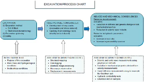
SRK’s approach to reviewing the engineering geology and rock engineering aspects of an excavation process is as illustrated in Figure 1-1. The key inputs for an excavation are the purpose of the excavation and geological conditions, which in principal define the method of excavation, design layout and construction approach. Cost is another factor, which is most likely one other reason for SKB opting for drill-and-blast method for excavation at Forsmark.
The ultimate goal though, is that, the excavation must perform its safety functions in the longest term possible. In the case of Forsmark, to provide the safest environment for deposition of used nuclear fuel. Very often the functions and performance of the excavation is challenged by the method of excavation itself. Damage to the
remaining rock can impair the performance and function of the facility. For a repository, damage to the remaining rock can provide a pathway for inflow and
outflow of fluids, including a pathway for radionuclides to escape into the biosphere. It is therefore necessary to assess, both qualitatively and quantitatively, the impact of the excavation on the surrounding rock, as well as on the engineered systems to ensure the long-term safety of the repository. In the case of a repository, the rock will function as the main natural barrier for the repository, while the excavations, which have no barrier functions, will facilitate the operations of the repository. Engineered barriers such as buffer, backfills and plugs will function to guarantee the initial conditions necessary to isolate used nuclear fuel in place.
Figure 1-1:SRK’s approach to reviewing Engineering Geology and Rock Engineering processes.
1.2. Forsmark Site
1.2.1. Forsmark Area
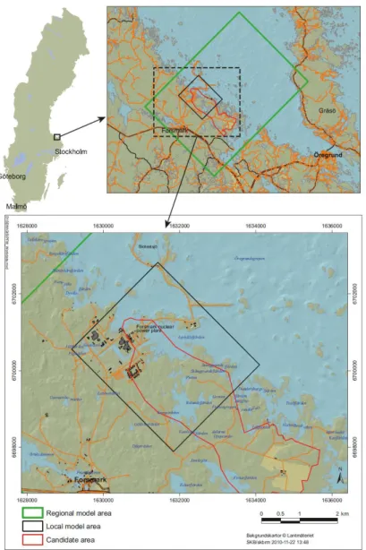
Forsmark is located 120 km north of Stockholm (Figure 1-2) and is situated along the Öregrundsgrepen shoreline of the Baltic Sea. The candidate area for site
investigation at Forsmark is approximately 6 km long and 2 km wide. The Forsmark nuclear power plant is located just outside the candidate area.
Figure 1-2:The Forsmark site and its location in Sweden. The KBS-3 repository is planned to be placed in the Candidate area within the Local model area (after Fig. 4-3, SKB TR-11-01).
1.2.2. Geomechanical description of the Forsmark site
SRK has not reviewed the details of the site characterization, but the summary report of the site characterization in report SKB TR-11-10, Chapter 4. SRK notes that a comprehensive site characterization work has been carried out over the course of a decade that resulted in a cross-disciplinary Site Descriptive Model (SDM), with inputs from geology, hydrology, rock mechanics, geochemistry and other branches involved in geosphere science. SKB indicates high confidence in its site descriptive model. SRK therefore assumes that the development of underground design work is based on sound engineering data, although the SDM will be further refined when new data becomes available during the construction of the repository and design will be updated.
From the construction point of view the site consist of a hard rock mass system (intact rock strength > 200 MPa) with sparsely distributed fractures. The rock mass within the candidate area has been divided into rock, fracture and thermal domains according to major structures and rock composition. This allows for underground design considerations as well as detailed hydrological, geophysical and thermal analyses. A comprehensive rock structural model has also been developed, which identifies the key deformations zones, i.e. zones which have poorer properties and may be at risk of shear movements. Rock domains outside the Candidate area have also been investigated. Investigations also included potentials for mineral resources in the area.
1.2.3. Rock stresses at Forsmark
Rock stresses are a very important factor in underground design. Rock stresses are the determining factor of repository layout at Forsmark since the deposition tunnels will be oriented parallelly to the orientation of the major principal stresses to minimise stress induced damages.
SRK cannot verify the level of confidence on the rock stress model from the summary results presented in SKB TR-11-01, Chapter 4. However, a citation has been made to a PhD thesis work by Daniel Ask (Ask, 2004). It is clear from Ask’s work that, there are uncertainties concerning the stress measurement data, especially the variability of the stresses data between different stress measurement methods. SRK’s own experiences in mining can also confirm the difficulties in accurately determining the rock stresses.
Indirect and direct stress measurements indicate that the maximum and intermediate principal stresses are horizontal, while the minimum principal stresses is vertical in the Forsmark area. This stress pattern generally conforms to stress indicators in the Scandinavian rock belt. The maximum principal stress is oriented in angle in the range of N120 to N150.
1.3. Design Premises
The premises are the reference design parameters or criteria used by SKB for the design of the whole repository system, from production to closure. The premises for the repository are subjected to refinement and further development when new data becomes available during the construction and operation of the underground repository and further testing of the operational procedures.
Although there are reports available on the derivation of various design parameters and/or criteria, SRK did not review these reports as they were outside the scope of SRK’s review assignment. Nevertheless, SRK believes that, given the sensitivity of the project, the design premises should be reviewed and verified by independent experts.
1.4. Concept of the KBS-3 repository
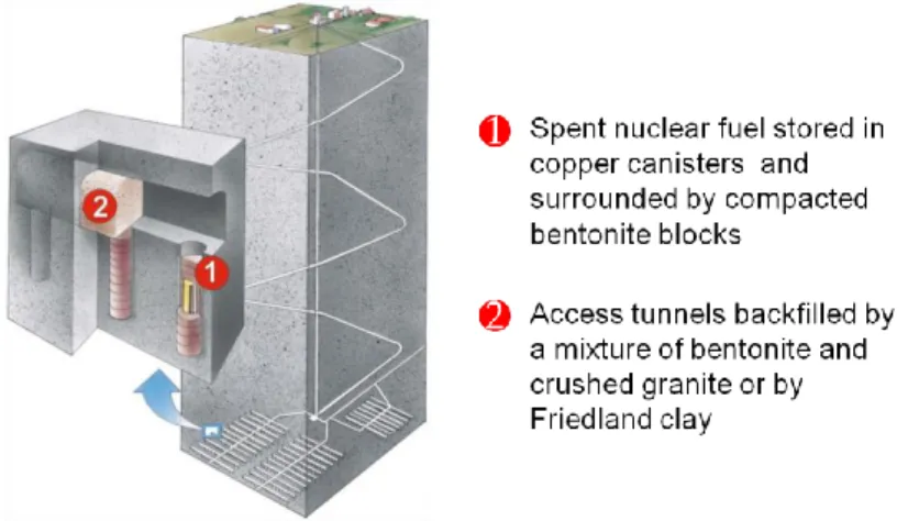
The KBS-3 repository concept involves burial of spent nuclear fuel in vertical (3V) or horizontal (3H) deposition holes in a hard rock mass. The
KBS-3V concept (Figure 1-3) is utilized by SKB as the reference burial concept at Forsmark.
In principle the spent nuclear fuel (stored in a copper canister) is placed in a deposition hole and then surrounded by compacted bentonite blocks. The access tunnels are backfilled with a bentonite mixture. The rock mass around the repository will be main natural barrier.
Figure 1-3: SKB’s concept KBS-3 for the disposal of spent nuclear fuel.
1.5. Repository construction
The main rock construction works will involve three stages; (i) excavation of the ramps and shafts, Central Area and Main tunnels, (ii) excavation of the Deposition tunnels, (iii) boring of deposition holes and (iv) partial sealing and closure. The main excavations types are categorized into various functions shown in Table 1-1. Table 1-1:Excavation types and functions in the KBS-3 repository at Forsmark.
Excavation Function
Ramp Transportation of canisters and construction equipment
Skip and elevator shafts
Ventilation, man transport, handling of waste rock, bentonite blocks, backfill material
Ventilation shafts Intake air and exhausted air circulation
Central area Underground spaces for operation and maintenance of the deposition work and excavation work activities
Transport tunnels Movement of equipment, material and men Main tunnels Access to deposition tunnels
Deposition tunnels Access to the deposition holes Deposition holes For deposition of canisters
1.6. Repository layout and operation
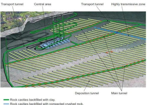
Figure 1-4 shows the layout of repository at Forsmark. One of the major controlling factors in this layout is the orientation of the maximum principal stress in the Forsmark area. The deposition tunnels are oriented parallel to the orientation of the maximum principal stress in order to minimise stress induced damage to the deposition tunnels and holes.
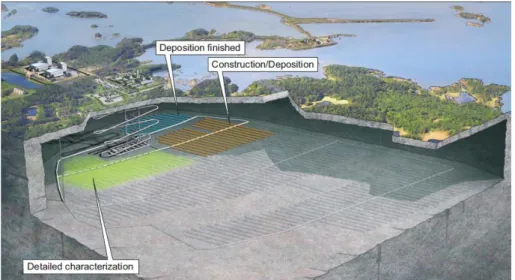
The operational sequence will involve simultaneous activities. The deposition area (deposition holes and tunnels) will be developed, while the deposition of canisters, and backfilling and sealing occur simultaneously in previously developed areas (Figure 1-5). This indicates a highly procedure-driven sequence of activities and will require a high level of efficiency and accuracy of the deposition and backfilling processes. Undesired disturbances must be minimised or even be completely eliminated.
Figure 1-4:The general layout of the KBS-3 repository at Forsmark (after Fig. 1-4, SKB R-11-14).
Figure 1-5:Sequence of activities during the operation of the KBS-3 repository at Forsmark (after Fig. 4-5, SKB R-11-14).
2. Rock Engineering and Engineering
Geology aspects
2.1. Repository depth
The repository will be located between 450 and 500 m (470 m is used in the reference design) below the ground surface (Figure 1-4 and 1-5). The basis for the choice of the repository depth is the SER Report (SKB R-08-83) and the
Underground Opening Construction Report (SKB TR-10-18). Risk of spalling due to high stresses has been taken into account in choosing the depth of the repository at Forsmark.
2.2. Construction methods
SKB’s reference method for developing the access drifts, transport tunnels and deposition drifts is drill-and-blast. The deposition holes and shafts will be excavated by boring. SKB believes it has refined the cautious and smooth blasting techniques to achieve the tunnel profiles as well as maintain minimal damage to the rock surrounding the underground openings. Cost factor may have also played a part in SKB’s choice of choosing drill-and-blast method (over mechanical excavation) and refining the method to meet the requirements defined in the premises for the design of the repository.
SRK has sighted other reports (e.g. Olsson et al., 2004) to understand the efforts in studies related to excavation by drill-and-blast and mechanical excavation. The study by Olsson et al., (2004) at SKB’s Äspö HRL shows that, it is possible to minimise the damage induced by blasting with controlled blasting techniques (smooth and cautious). SKB defines the damage of the rock mass due to excavation as the zone in which the irreversible damage to rock has occurred such that the mechanical and hydraulic properties have been significantly affected (Excavation Damage Zone).
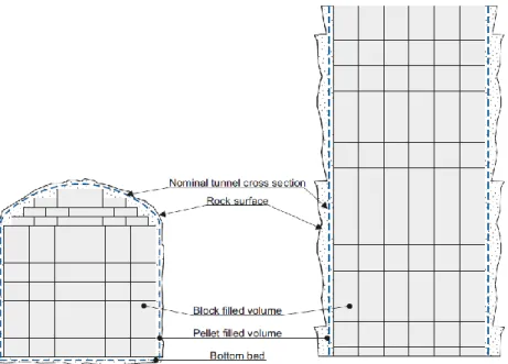
A major disadvantage of the drill-and-blast method though is the uneven profile of the tunnel surface. Given that the backfilling of the tunnels with bentonite blocks and pellets will have to meet the required density stated in the premises for backfilling, the task of filling the uneven volume becomes tedious (Figure 2-1). The uneven surfaces are formed due to overbreak (breakage beyond the design profile) and the necessary look-out angle for the blasting holes.
Figure 2-1:Scheme showing the Deposition tunnel contours and the backfilling by means of bentonite blocks and pellets. Irregular tunnel surface are created by drill-and-blast. Backfilling activities can be time consuming (after Fig. 3-2, SKB TR-10-16).
2.3. Excavation Damaged Zone (EDZ)
The excavation process will results in the disturbance and damage to the rock around the excavation (Figure 2-2). Various definitions have been given for damage related to excavation works in rock radioactive waste isolation studies (e.g. Bernier and Davies, 2004). These definitions basically depend on the geological media in which the excavation is carried. SKB defines the Excavation Damaged Zone (EDZ) as the zone of irreversible damage to rock to differentiate from deformations that do not permanently affect rock such as elastic deformations. SKB believes that, the effect of EDZ induced by the excavation on the barrier function of the rock is negligible. The blast-induced radial cracks do not form continuous paths along the Deposition tunnels and the crack lengths generally average between 0.1 to 0.3 m (Olsson et al., 2004). Therefore SKB concludes that continuous EDZ will not develop.
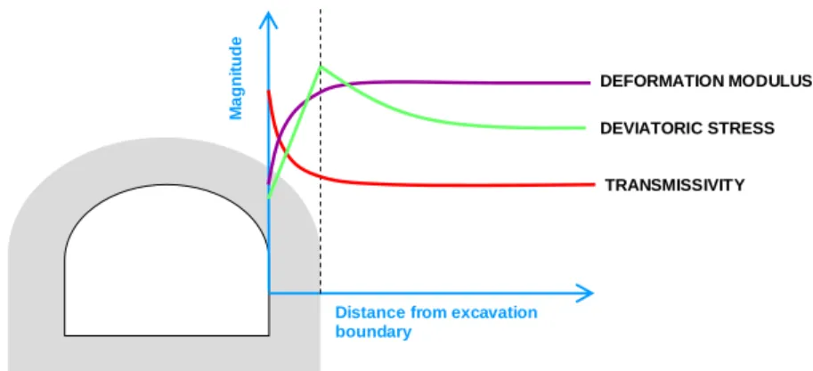
The general characteristics of the EDZ in terms of mechanical and hydraulic parameters are shown in Figure 2-3. Within the EDZ the rock mass deformation modulus and induced boundary stresses are lower. The transmissivity is generally believed to increase within the EDZ. However, there are evidences where it is much lower within the EDZ, which depends on the fracture characteristics and state of induced stresses.
Figure 2-2:Blast induced and stress-induced cracks around a drill-and-blast tunnel. Stress-induced cracks can develop as result of stress re-distribution around the excavation.
Figure 2-3:Behaviour of the mechanical and hydraulic properties of the rock mass around the tunnel boundary. Within the damage zone the rock mass deformation modulus and induced stresses are lower due to rock damage. The transmissivity is generally higher within the damage zone, but in some cases it can be lower, which depends on the fracture characteristics and the state of stresses.
2.4. Spalling
Spalling damage can either be stress induced or thermally induced by the heat generated by spent nuclear fuel. SKB has identified the risk of spalling around the deposition holes and tunnels. Thermally induced spalling, which may occur in the later stages after deposition of the canisters, has been investigated by SKB (e.g. Andersson, 2007; SKB TR-07-01; SKB TR-10-23). The thermally induced spalling showed the tendency to break rock slabs parallelly to the orientation of the major principal stresses (Figure 2-4). The risk is that, if the induced stresses are already very high due to high in-situ stresses and the rock is heated, spalling would occur. However, the extent of spalling depends on the thermal properties of the rock itself, and SKB states that this has been thoroughly investigated leading to the conclusion that spalling strength, with thermal coupling, between 52 to 62% of the uniaxial compressive strength of the intact rock (e.g. SKB TR-10-23). The hypothesis that the counter pressure provided by self-weight or by expansion of the bentonite can effectively suppress the spalling or at least keep the spalled slaps in place and thereby reducing the hydraulic transmissivity of the EDZ, is found to be
inconclusive (SKB TR-10-37). SRK also agrees that the expansion of bentonite, which will provide a counter pressure of 200 kPa, may not be sufficient to suppress
Blast-induced cracks Half-pipes or half-casts Natural cracks Stress-induced cracks Half-casts or half-pipes
Blast-induced
cracks
Stress-induced
cracks
Natural
cracks
Half-casts
DEFORMATION MODULUS TRANSMISSIVITY DEVIATORIC STRESSDistance from excavation boundary M a g n itu d e
spalling. Therefore the subject of stress-thermo coupled spalling may need further investigation.
2.5. Acceptance/rejection criterion for deposition holes
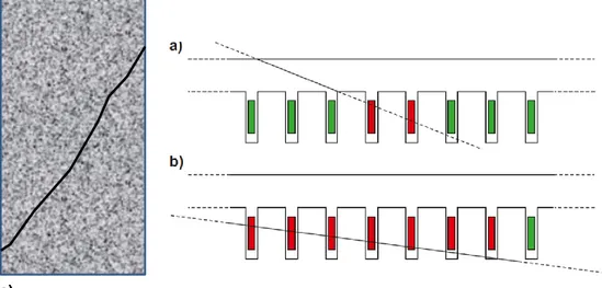
The basis for accepting/rejecting deposition holes suitable for guarantee long-term safety of the repository is called Extended Full Perimeter Criterion or EFPC (Figure 2-5), which relies on visually identifying the intersecting structures. Deposition holes are rejected based on the two criteria stated in SKB TR-10-18:
a) Deposition positions being intersected by a fracture that intersects the full tunnel perimeter and that also is projected to intersect the canister location in the deposition hole are rejected (FPC)
b) Deposition positions intersected by a fracture intersecting four or more additional potential deposition positions are rejected (EFPC).
SKB accepts that the existence of water bearing fractures have to be considered when applying EFPC for assessing the deposition holes.
Figure 2-4:Thermally induced spalling in a deposition hole (after Andersson, 2007). The spalling cracks run parallelly to the orientation of the major principal stress.
c)
Figure 2-5:(a) Deposition positions being intersected by a fracture that intersects the full tunnel perimeter and that also is projected to intersect the canister location in the deposition hole are rejected (FPC), (b) Deposition positions intersected by a fracture intersecting four or more additional potential deposition positions are rejected (EFPC) (after Fig. 4-2, SKB TR-10-18), (c) schematic fracture trace on a tunnel wall.
2.6. Operation
SKB has a reference procedure for transportation and handling of spent nuclear fuel in the deposition areas. Each deposition hole is firstly prepared one at a time with bentonite buffer blocks. After placing the canister in the deposition hole the deposition hole is backfilled, followed by backfilling of the deposition tunnel. The cycle is repeated until the last deposition hole is completed and the deposition tunnel is backfilled and sealed. This has been pointed in the report SKB R-08-59.
2.7. Partial sealing and Closure
Partial sealing and closure are designed to guarantee the isolation of the radioactive waste. Partial sealing addresses the reversible isolation of the waste in the deposition tunnels before final closure of the repository. In order words the deposition hole can be accessed if necessary. Closure is the set of activities to obtain irreversible isolation of the waste in the long-term. In other words the deposition areas are permanently closed and made inaccessible for re-entry in the future.
The design premises provide the specification for the design of the seal and closure, which mainly comprise specifications for backfills and plug for different types of excavation and their functions. Plugs serve two main purposes; for keeping the backfill place and for sealing transmissive zones (Figure 2-6). The plugs have no long-term performances besides maintaining their volume in time.
The sealing and backfilling materials will comprise of low pH (pH<11) and low permeability (transmissivity <10-10 m2/s) bentonite clay at least in the deposition tunnels, while access ramps and tunnels above -200 m the requirement is emphasized.
Figure 2-6:Different types of plugs and backfill will apply to different parts of the repository depending on the function of the excavations (after Fig. 3-1, SKB TR-10-17).
3. Review findings: Initial Review Phase
3.1. In-situ stresses
Since the in-situ stress is a very important determining factor for the repository location, layout and design, it absolutely necessary that SKB has very high confidence in the stress measurements. SRK’s experience with the mining industry is that, despite extensive stress measurements, precisely quantifying the magnitude and orientation of the in-situ stresses has always remained elusive. Different
techniques produce far varying results. Ask (2007) clearly indicates the uncertainties of the stress data concerning stress measurement data at SKB’s candidate sites for nuclear waste repositories.
3.2. Excavation method
SKB’s reference excavation method will be drill-and-blast, except for the deposition holes and shafts, which drilled using diamond drills. Although SKB has high confidence in the drill-and-blast method with refined cautious and smooth blasting techniques, SRK believes that the mechanical excavation alternative should not be totally excluded. There are practical difficulties though with mechanical excavations especially with the difficulties of the manoeuvring the machines underground. However, there are technologies to design mechanical equipment to the demands of the Forsmark site. SRK also believes that an option study needs to be carried to see how each excavation method will affect the operations as well as the impact on the rock due excavation and stress re-distribution.
3.3. Excavation Damaged Zone (EDZ)
SRK understands that the hydraulic properties of the EDZ are very important for the repository. Although SKB concludes that the transmissivity within the EDZ will be lower than the reference transmissivity limit of 10-8 m2/s, SRK believes that an independent verification of this reference value could be necessary.
3.4. Acceptance/rejection criterion for deposition holes
SRK observes that it is not clear how the acceptance/rejection criterion for deposition holes (EFPC) will be used to:
1. Quantify the extent of the fractures,
2. Identify a blind fracture structures, i.e. structures not visible in a deposition hole but passing within a critical radius from the deposition hole,
3. Identify continuity when EDZ is taken into account, i.e. a fracture may not intersect the deposition hole but could be intersected by EDZ,
4. Identify the same fracture on the tunnel walls and/or different deposition holes.
SRK believes that the method for rejecting deposition holes needs further improvements. Reliable techniques to identify blind fracture structures, quantify their extent, determine their water bearing potential and history and future evolution need to developed and tested. The use of EFPC to reject deposition wholes need to be coupled with other techniques (e.g. geophysics) by means of which, for example, blind structures can be identified.
3.5. Sequential excavation
Sequential excavation has the potential to induce damage to the previously excavated deposition holes and tunnels due to the stress-redistribution, blast vibrations and heavy vehicle traffic. SKB believes blast vibrations and repeated cycle loadings will not be significant enough to harm the deposition holes and tunnels (SKB TR-11-01). However, stress re-distribution may encourage spalling around deposition holes. Since the deposition holes are located in the floor of the deposition tunnels the stress could still be sufficiently high to induce spalling. The risk of spalling in the deposition holes still needs to be properly addressed.
3.6. Operation
SRK visualizes the activities of emplacement of buffer blocks, deposition, and backfilling of the deposition tunnels to be highly procedure driven, given the demand for deposition of 1 to 2 canisters per day, with down time to be kept to minimum or none at all. SRK also believes cycle of activities leading up to the placement of the nuclear fuel canisters and the backfilling processes are not particularly time and operationally attractive. This has also been addressed by SKB’s studies on backfilling.
The reference backfilling procedure of single block placement on stacks and blowing of pellets into the gaps is operationally inefficient. Recommendations have been made for SKB to improve the backfilling methods, with suggestion of pre-assembled block placement method. SRK also believes this is the better option. The risk of deposition holes being subject to vibrations and damage due the movement of heavy equipment over the pre-drilled deposition holes (which will be covered with metal plates) cannot be avoided with the present procedures.
The handling of the canister during the placement inside the deposition hole is also practically challenging. The suspension of the heavy canister over a tight deposition hole, with a clearance of less than 10 mm, is practically difficult and the possibility to the damage canister cannot be ignored. The deposition holes must also be drilled with very high precision.
The tunnel temperature will also be altered due to the heat generated from the deposited canister. This will require proper ventilation. SKB reports sighted by SRK do not indicate ventilation procedures or controls for the deposition tunnels.
3.7. Backfilling methods
Three backfilling methods have been described in SKB R-08-59. These are:
1. Block Method – which is the reference method, handling backfilling blocks is manual, tested by SKB
2. Robot Method – automated handling of blocks, need to be developed and tested
3. Module Method – pre-assembled placement units blocks, need to be developed and tested.
It is clear from this report that the Block Method, which is the reference method in SKB’s application, and the Robot Method are operationally inefficient. It was therefore recommended to SKB to consider the Module Method, which will involve backfilling with pre-assembled blocks to guarantee better performance and accuracy. SRK also considers this as a more appropriate option. However, it is not clear whether SKB will implement the recommendations in SKB R-08-59.
3.8. Backfill as rock support
It is not clear whether the backfill of the deposition tunnels, besides being an engineered barrier, will also perform rock support functions. It is noted that the swelling of bentonite will provide a support pressure of 200 kPa, which is quite insignificant for any rock support functions. It is also not clear if SKB has performed a study on the mechanical interaction (e.g. support and stabilizing pressure) between the backfill and the rock.
3.9. Partial sealing and closure
It must be admitted that the definition for partial sealing and closure are not very clear, in SKB documentation. For example, in the Backfill Report SKB TR-10-17 the terms have been used with very little distinction.
4. References
Apart from reviewing the requested SKB reports and chapters and sections in Appendix 1, additional citations were made to other relevant publications. These are listed below:
Andersson C. J., 2007. Rock Mass Response to Coupled Mechanical Thermal Loading, Äspö Pillar Stability Experiment. PhD Thesis, Division of Soil and Rock Mechanics Department of Civil and Architectural Engineering, Royal Institute of Technology, Stockholm, Sweden.
Ask D., 2004. New developments of the Integrated Stress. PhD Thesis, Division of Soil and Rock Mechanics Department of Civil and Architectural Engineering, Royal Institute of Technology, Stockholm, Sweden.
Bernier F., Davies C., 2004. Impact of the Excavation Disturbed or Damaged Zone (EDZ) on the Performance of Radioactive Waste Geological Repositories, EUR 21028 EN, Luxembourg.
SKB R-04-73. Olsson M., Bengt N., Lasse W., Andersson C., Christiansson, R., 2004. Äspö HRL: Experiences of blasting of the TASQ tunnel, Svensk
Kärnbränslehantering AB
.
SKB R-05-71. Martin D., 2005. Preliminary assessment of potential underground stability (wedge and spalling) at Forsmark, Simpevarp and Lexmark sites, Svensk Kärnbränslehantering AB.
SKB TR-07-01. Andersson C.J., 2007. Äspö Pillar Stability Experiment, Final Report. Rock mass response to coupled mechanical thermal loading, Svensk Kärnbränslehantering AB.
SKB R-08-83, 2009, Site engineering report Forsmark. Guideliness for underground design, Step D2. Svensk Kärnbränslehantering AB.
SKB TR-10-23, Hökmark H., Lönnqvist M., Fälth B., 2010. THM-issues in repository rock. Thermal, mechanical, thermo-mechanical and hydro-mechanical evolution of the rock at the Forsmark and Laxemar sites, Svensk
Kärnbränslehantering AB.
SKB TR-10-37, Glamheden R., Fälth B., Jacobsson L., Harrström J., Berglund J., Bergkvist L., 2010. Counterforce applied to prevent spalling, Svensk
APPENDIX 1
Coverage of SKB reports
Table A-1: Reports covered by SRK in this assignment for SSM’s Initial Review Phase. Reviewed report Reviewed sections CommentsTR-11-01 Ch.4, Sec. 5.6-5.8, 10.2 10.3.4-5, 10.3.14-15 10.4.3-4, 10.4.10, 15.5.10, 15.5.12, 15.5.15-20, 15.6.2, 15.6.6-8, 15.7.4 TR-11-01 is a key summary report of repository site or the SR-site. TR-11-10 is a three-volume report. The three volumes summarize and outline; the purpose, site descriptions of Forsmark, design premises, evolution of the repository (construction to closure), safety
TR-10-12 3.5-3.8, 4.7-4.9 Design and production of the KBS-3 repository
TR-10-16 Ch.2-4, 6-10, Sec. 5.4, Design, construction and initial state of the backfill and plugs in the deposition tunnels, Ch. 7-9 concerned with concrete plugs. TR-10-17 All Design, construction and
initial state of the closure TR-10-18 Ch.2-4 Design, construction and
initial state of the underground openings TR-09-22 3.3-3.5 Safety related design
premises for a KBS-3V, sections
R-08-116 Ch.1-2, 4, Appendix C Underground design Forsmark. Layout from Design Stage 2 or D2 R-08-59 Ch.2-3,6-8 Backfilling of the KBS-3V
deposition tunnels – possibilities and limitations R-11-14 Sec. 1.4, Ch.2, 4, 7 Framework program for
detailed characterisation in connection with the construction and operation the final repository
APPENDIX 2
Suggested needs for
complementary information
from SKB
Essential questions to SKB requiring clarifications, complementary information, complementary data, etc., as discussed in detail in this review report include the following:
1. Excavation Damaged Zone (EDZ): SRK understands that the hydraulic properties of the EDZ are very important for the repository. Although SKB concludes that the transmissivity within the EDZ will be lower than the reference transmissivity limit of 10-8 m2/s, the basis for this value is not clearly understood by SRK. Perhaps some references regarding the derivation of this value would provide the clarification. The mechanical interaction of the EDZ and backfill would be interesting to see as the softer skin of the EDZ is being compressed by the swelling bentonite. Perhaps the compression of EDZ by the bentonite may assist in closing the fractures and thereby further reducing the hydraulic transmissivity. The presence of the EDZ may also reduce the spalling potential around the excavation boundaries by pushing high stresses further into the rock due to its low stiffness. EDZ should therefore be included in spalling
investigations.
From a stability point of the view, the strength and stiffness of the EDZ are important for the stability of the excavation. There seems to be no design premises for the strength and stiffness of EDZ and for the long-term stability of the excavations and support design.
2. In-situ stresses: Since the in-situ stress is a very important determining factor for the repository location, layout and design, it absolutely necessary that SKB has very high confidence in the stress measurements. SRK’s experience with the mining industry is that, despite extensive stress measurements, precisely quantifying the magnitude and orientation of the in-situ stresses has always remained elusive. Different techniques produce far varying results. Ask (2007) clearly indicates the uncertainties of the stress data concerning stress measurement data at SKB’s candidate sites for nuclear waste repositories.
3. Excavation method: SKB’s reference excavation method will be drill-and-blast, except for the deposition holes and shafts, which drilled using
diamond drills. Although SKB has high confidence in the drill-and-blast method with refined cautious and smooth blasting techniques, SRK believes that the mechanical excavation alternative should not be totally excluded. There are practical difficulties though with mechanical excavations especially with the difficulties of the manoeuvring the machines underground. However, there are technologies to design mechanical equipment to the demands of the Forsmark site. SRK also believes that an option study needs to be carried to see how each excavation method will affect the operations as well as the impact on the rock due excavation and stress re-distribution.
4. Acceptance/rejection criterion for deposition holes: On the other hand it is not clear how the EFPC will be used to:
a. Quantify the extent of the fracture,
b. Identify a blind structure, i.e. a structure not visible in deposition hole but passes within a critical radius from the deposition hole, c. Identify continuity when EDZ is taken into account, i.e. a fracture
may not intersect the deposition hole but could be intersected by EDZ,
d. Identify the same fracture on the tunnel walls and/or different deposition holes.
SRK believes that the method for rejecting deposition holes needs further improvements. Reliable techniques to identify blind fracture structures, quantify their extent, determine their water bearing potential and history and future evolution need to developed and tested. The use of EFPC to reject deposition wholes need to be coupled with other techniques (e.g. geophysics) by means of which, for example, blind structures can be identified. Advancement in ground penetration radar technology will most likely assist SKB in identifying the blind structures.
5. Sequential excavation: Sequential excavation has the potential to induce damage to the previously excavated deposition holes and tunnels due to the stress-redistribution, blast vibrations and heavy vehicle traffic. SKB believes blast vibrations and repeated cycle loadings will not be significant enough to harm the deposition holes and tunnels (SKB TR-FF-FF). However, stress re-distribution may encourage spalling around deposition holes. Since the deposition holes are located in the floor of the deposition tunnels the stress could still be sufficiently high to induce spalling. The risk of spalling in the deposition holes still needs to be properly addressed. 6. Operation: SRK visualizes the activities of emplacement of buffer blocks,
deposition, and backfilling of the deposition tunnels to be highly procedure driven, given the demand for deposition of 1 to 2 canisters per day, with down time to be kept to minimum or none at all. SRK also believes cycle of activities leading up to the placement of the nuclear fuel canisters and the backfilling processes are not particularly time and operationally attractive. This has also been addressed by SKB’s studies on backfilling.
The reference backfilling procedure of single block placement on stacks and blowing of pellets into the gaps is operationally inefficient.
Recommendations have been made for SKB to improve the backfilling methods, with suggestion of pre-assembled block placement method. SRK also believes this is the better option.
The risk of deposition holes being subject to vibrations and damage due the movement of heavy equipment over the pre-drilled deposition holes (which will be covered with metal plates) cannot be avoided with the present procedures.
The handling of the canister during the placement inside the deposition hole is also practically challenging. The suspension of the heavy canister over a tight deposition hole, with a clearance of less than 10 mm, is practically difficult and the possibility to the damage canister cannot be ignored. The deposition holes must also be drilled with very high precision.
The tunnel temperature will also be altered due to the heat generated from the deposited canister. This will require proper ventilation. SKB reports sighted by SRK do not indicate ventilation procedures or controls for the deposition tunnels.
7. Backfilling methods: Three backfilling methods have been described in SKB R-08-59. These are:
a. Block Method – which is the reference method, handling backfilling blocks is manual, tested by SKB
b. Robot Method – automated handling of blocks, need to be developed and tested
c. Module Method – pre-assembled placement units blocks, need to be developed and tested.
It is clear from this report that the Block Method, which is the reference method in SKB’s application, and the Robot Method are operationally inefficient. It was therefore recommended to SKB to consider the Module Method, which will involve backfilling with pre-assembled blocks to guarantee better performance and accuracy. SRK also considers this as a more appropriate option. However, it is not clear whether SKB will implement the recommendations in SKB R-08-59.
8. Backfill as rock support: It is not clear whether the backfill of the deposition tunnels, besides being an engineered barrier, will also perform rock support functions. It is noted that the swelling of bentonite will provide a support pressure of 200 kPa, which is quite insignificant for any rock support functions. It is also not clear if SKB has performed a study on the mechanical interaction (e.g. support and stabilizing pressure) between the backfill and the rock.
9. Partial sealing and closure: It must be admitted that the definition for partial sealing and closure are not very clear, in SKB documentation. For example, in the backfill report TR-10-17 the terms have been used with very little distinction.
APPENDIX 3
Suggested review topics for
SSM
1. Excavation in the vicinity of sealed Deposition tunnels: Rock mechanics response of the sealed deposition tunnels during sequential excavation. Stress re-distribution, ground deformation, blast vibrations and heavy vehicle traffic could affect depositions areas that have sealed after deposition.
2. Mechanical response of the rock and backfill interaction: It is not clear if the backfill will also perform rock support functions, besides being engineered barriers. Studies about the interaction between rock and backfill have to be carried to observe the kind and amount of interaction at this interface.
3. In-situ stress model: In-situ stress measurements, an independent verification of the stresses should be carried out. This is critical since the entire layout of the deposition tunnels and the safety of the isolation of the waste depend on the orientation and magnitude of the rock stresses. 4. Methods for acceptance/rejection of deposition holes: Rejecting a
deposition hole is presently based on EFPC. It is difficult to identify blind structures with this method. A reliable method for determining blind structures as well as the extent is needed. Possibly, one could look into recent advancements in ground penetration radar technology which may assist in identifying the blind structures.
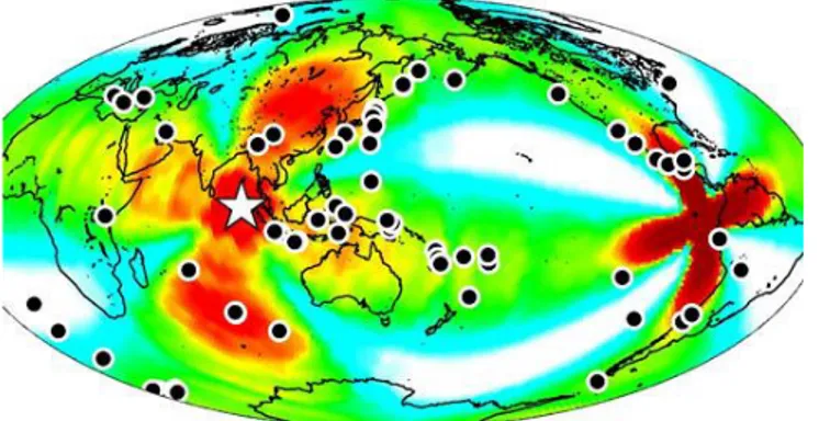
5. Earthquakes: The likelihood and consequences of earthquakes needs to be clarified further. Plate tectonics play the most crucial role in natural earthquakes. Sweden is not located within or near any tectonically active zones and therefore is regarded as low risk for the natural earthquakes due to plate movements. Rebound due to melting glacial ice can cause earthquake. There is certainly a possibility for natural earthquakes due to weight relieve and ground rebound. Global weather pattern has also changed dramatically over the last century, including observation of unusual weather and seismic patterns. Consider for example the 8.6 magnitude earthquake that shook the floor of the Indian Ocean off the island of Sumatra on April 11, 2012. USGS (United States Geological Survey) reports that it was not just unusual because of its size – 10th largest earthquake in the last century – it also set off a series of earthquakes around the world for up to 6 days afterwards. Figure A2-1 (from USGS) shows the map of the earthquakes triggered by the single earthquake off the coast of Sumatra. Hence, we cannot ignore such events (which apparently have an occurrence rate of 10 in every 100 years) and the chances this kind of event will occur during the construction phase of the repository can be considered likely. There are recorded evidences of earthquakes generated by mining
activities in Sweden. Therefore the chances of triggering earthquakes due to the excavation process at Forsmark are also a possibility.
Figure A2-1:A USGS map of the series of earthquakes triggered by the 8.6 magnitude earthquake that occurred off the shore of Sumatra on April 11, 2012.
2012:53 The Swedish Radiation Safety Authority has a comprehensive responsibility to ensure that society is safe from the effects of radiation. The Authority works to achieve radiation safety in a number of areas: nuclear power, medical care as well as commercial products and services. The Authority also works to achieve protection from natural radiation and to increase the level of radiation safety internationally. The Swedish Radiation Safety Authority works proactively and preventively to protect people and the environment from the harmful effects of radiation, now and in the future. The Authority issues regulations and supervises compliance, while also supporting research, providing training and information, and issuing advice. Often, activities involving radiation require licences issued by the Authority. The Swedish Radiation Safety Authority maintains emergency preparedness around the clock with the aim of limiting the aftermath of radiation accidents and the unintentional spreading of radioactive substances. The Authority participates in international co-operation in order to promote radiation safety and finances projects aiming to raise the level of radiation safety in certain Eastern European countries.
The Authority reports to the Ministry of the Environment and has around 270 employees with competencies in the fields of engineering, natural and behavioural sciences, law, economics and communications. We have received quality, environmental and working environment certification.