Reprinted from
APAlL, 1976
THE
PHYSICS
TEACHER
Advances in Solar Heating
and Cooling Systellls
Dan S. Ward
At the advent of a worldwide crisis in energy consumption andsupply, interest in the sun as an alternative source of energy has increased dramatically. The impressive attributes of solar energy: the unlimited supply at zero fuel cost, the fact that it is nonpolluting, and its wide distribution over the earth, make this undeveloped energy source enormously attractive. An energy resource that cannot be exhausted or subject to price increases, that is environmentally ideal, and totally immune to political embargo must be considered a prime alternative to the conventional energy fuels.
Solar energy does have some disadvantages; most notably an intermittent and diffuse nature. But engineering technology is quite capable of overcoming the difficulties of a low energy density as well as the day-to-day and weather-induced fluctuations of the solar radiation. The prime obstacle, however, to the widespread utilization of solar energy is economics. Solar energy can provide virtually any form or amount of useful energy needs, if we are willing to pay the cost.
Because of the complex economics of solar energy, we are only now arriving at a point where it can hope to compete in the market place with conventional fuels. Solar heating and cooling of buildings represent the best near term possibility for economical competitiveness. And because of this, a large and varied research and development effort on economical solar heating and cooling systems is now being conducted. This has provided for some impressive advances in solar energy technology; this paper will discuss several of the most noteworthy advances. A basic criterion for the choice of these ideas is that of a potential near term commercial feasibility .
Solar collectors
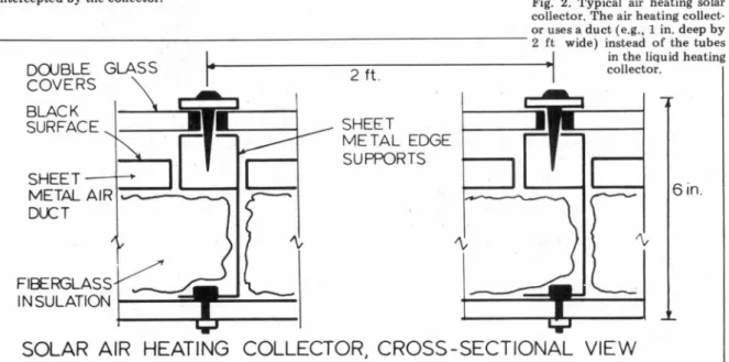
A solar collector is nothing more than a means of accepting incident solar radiation with the capability of delivering useful energy, usually in the form of heat. Figures 1 and 2 show simple, baseline, flat-plate collectors capable of using solar heating and cooling systems. Essentially each collector consists of an absorber plate (commonly a black metal surface) which absorbs the incident solar radiation and converts the solar energy to heat, which can be transferred to another part of the system by utilizing some appropriate heat transfer fluid. In the process of collecting energy, the absorber plate will, of course, tend to come to thermal equilibrium with its surroundings by giving up heat. The solar collector other than the absorber plate is designed for the single purpose of reducing these heat losses from the absorber plate.
Heat may be lost from the absorber plate by the three methods of heat transfer: radiation, conduction, or convection. Insulation beneath the absorber reduces all three methods of loss as does the transparent
Dan S. Ward has a Bachelor of Engineering Science and a Ph.D. in nuclear physics. He is an assistant professor of civil engineering and physics and assistant director of the Solar Energy Applications Laboratory at Colorodo State University. As project manager of three solar houses at CSU, Dr. Ward was responsible for the design, con-struction, ins ta/la tion, and evalu-ation of complete heating and cooling systems. (Colorodo State University, Fort Collins, Colorado 80523.)
Top Cover Glass
covers. A glass cover, for example, will be opaque to the thermal radiation from the plate and will reduce convection losses due to air movement across the collector. The air space between the absorber plate and cover/will act to reduce conduction losses between these two components. Improvements in solar collector design, then, have the common goal of significantly reducing heat losses from the absorber plate. The primary methods of accomplishing this fall into three categories: (1) use of selective surfaces to reduce thermal radiation losses; (2) use of an evacuated space to eliminate conduction and convection losses; and (3) reducing the effective heat transfer surface of the absorber plate without reducing the area of solar radiation intercepted by the collector.
Fig. 1. Typical liquid heating solar collector. The collector consists of insulation, an absorber plate with internally manifolded tubes (usually made of metal, e.g., copper, aluminum, or steel), transparent covers (typically glass), and the structural components to support the structure.
While selective surfaces represent an effective method of reducing absorber plate heat losses, details will not be discussed in this paper. In brief they involve coating with high absorbance for solar radiation and high transmittance for long-wave radiation, applied to substrates with low-emittance. Rather, emphasis will be placed on solar collector design configurations which can reduce conduction/convection heat losses. It is noteworthy that any design configuration can utilize a selective surface to further improve the overall collector efficiency.
If, in Fig. 1, the space between the absorber plate and lower cover glass is evacuated (a vacuum of lCf.3 - 1Cf4 torr ·
Fig. 2. Typical air heating solar collector. The air heating collect-or uses a duct (e.g., 1 in. deep by
~--- 2 ft wide) instead of the tubes
SHEET--+-+
METAL AIR, __
_.
DLCT
I
in the liquid heatingi.---•
collector.2
ft .SHEET
METAL EDGE
SUPPORTS
[~
6in.
Fig. 3 . Corning Glass Works evacuated tube solar collector. The heat transfer liquid flows through a single U-shaped tube which is bonded to a metal absorber plate. The space between the absorber and glass cylindrical wall contains a vacuum of approximately 10-3 -10-4 torr.
is established), the conduction and convection heat losses can be virtually eliminated. However, the difficulty of obtaining such a vaccum, and perhaps more important, of maintaining the vacuum would be indeed formidable, and undoubtedly expensive. The extensive areas of metal /glass seals and structural integrity of a plate glass cover under the resulting pressure differential, tend to eliminate this possibility.
However, we can achieve the benefits of an evacuated space between the absorber plate and glass cover by a method originally proposed by Speyer, 1 that of an
evacuated tube solar collector. Figure 3 shows the Coming evacuated tube solar collector. The evacuated space
virtually eliminates the conduction and convection losses, while the use of an appropriate selective surface reduces the thermal radiation losses. The only significant energy loss is in the optical losses (mostly reflection losses of = 14%) of the incident solar radiation on the glass tubes. However, appropriate glass treatments or coatings can reduce these optical losses by 50% or more. The result is a collector with achievable efficiencies of 80-90%, even under conditions of high temperature differentials between the absorber and surroun"dings. Figure 4 shows a schematic of another design of an evacuated tube, this one by Owens-Illinois. In this case, the inner glass tube acts as the absorber plate and eliminates the necessity of a metal/glass seal.
Because of the costs of manufacturing and costs of selective surface per unit area of absorber, a reasonable alternative to the evacuated tube collectors is to reduce the heat transfer surface of the absorber plate (without reducing the area of incident solar radiation). A solar concentrating collector does this by taking the solar radiation incident on a collector area and focusing it on a smaller absorber plate area. The disadvantages of solar concentrators are that the cost of mirrors and /or lens to focus the solar radiation, and the necessity to track the sun (a concentrator can utilize only the direct solar radiation) make it economically unfeasible.
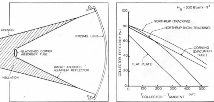
An exception to this general rule is the use of a Fresnel lens strip, a sort of longitudinal Fresnel lens, to concentrate the incident radiation on a linear absorber plate (Fig. 5). The Northrup Corporation has shown that the Fresnel lens strip can be easily extruded as a high grade plastic, at moderate cost. Under tracking conditions the concentration ratio, the ratio of the effective area of the aperture to the area of the solar absorber, is approximately ten. But a concentration ratio of four can be obtained by a nontracking collector oriented toward the south at an angle with the horizontal approximately equal to the latitude. The cost savings in terms of selective surfaces and the improved thermal efficiency make the Fresnel lens strip design a viable alternative.
Vacuum : Pressure P < 10·• Torr
Feeder Tube
F luid Flow Area : Supply
,,__-7~---Absorber Tube
Fig. 4. Owens-Illinois evacuated tube solar collector. The heat transfer fluid enters the collector through the inner tube (supply), flows into the space just outside the inner tube, and returns through the return fluid flow area. The evacuated space is between the two outer cylinders, with a selective coating on the innermost of the two tubes. T is
the transmissivity, a the absorp-tivity, and € the emissivity.
__ __::::7'"~~----~f---F1u1 d Flow Area Return
---,,..(_,~----Cover Tube T =.92
FRESNEL
LENS-BRIGHT ANODIZED ALUMINUM REFLECTOR
Fig. 5. Northrup Fresnel Jens strip solar collector. Signifi- · cant improvements in efficiency are accomplished by minimizing the heat transfer area of the absorber plate and thus reducing the heat Joss from the absorber.
The potential competitiveness of the Fresnel lens strip design and the evacuated tube solar collector can be demonstrated by plotting solar collector efficiency (useful energy collected divided by the incident solar radiation) against the temperature difference between the absorber plate and the ambient air temperature (as in Fig. 6). The improvements in collector efficiencies of the advanced designs are even more striking when one realizes that the solar collecting system will normally operate at a .t.T = 50-60°C (90-110° F).
The evacuated · tube solar collectors have one additional advantage. Because of the cylindrical shape, collector efficiency can be higher during the morning and evening than solar noon. The cylindrical shape provides for the same optical losses at all incident angles as the sun moves across the sky. Since the lower solar energy input in the morning and evening yields a lower operating temperature, the heat losses from the collector are reduced and the efficiency increased. This provides for a higher rate of solar collection during the entire day . When the collector efficiency is defined as a daily collector efficiency (i.e., the total useful energy collected divided by the total daily solar radiation), typical flat plate collectors have efficiencies of 20-30%. The evacuated tube solar collectors show daily efficiencies of 50-60%, doubling the collector's useful energy output.
Thermal storage
Once the incident solar radiation ·has been collected, suitable means must be provided to store the energy- for later use. While some solar applications may not require thermal storage, solar heating and cooling demands are usually out of phase with the available solar energy. In addition, some thermal storage is necessary as a damper to
100 80 ~
~
60 w Q LL LL w 40 Cl:'. ~h:l
..J 20d
u 0 0 HR = 300 Btu/hr ·ft 2 NORTHRUP (NON-TRACKING) 400 TCOLLECTOR - TAMBIENT (•F") 100 200Fig. 6. Collector efficiency as a function of temperature difference. HR is the incident solar radiation on a horizontal surface.
smooth out the fluctuations of available solar energy and provide an interface wit1' the collector system and the rest of the load.
The choice of the material for storing the energy has typically been limited to only a few possibilities. One of the most common methods is to store heat in a pepble-bed storage where rocks about the size of golf balls or larger receive heat from the collector system by air being passed· through the rock bed. The pebble-bed storage has several advantages including simplicity, potential high levels of thermal stratification in the thermal storage unit and low insulation requirements. As for this last point, unless air is actually being passed through the pebble-bed (storing heat or removing heat to be delivered to load) only minimal insulation is required (about 3-1h in. batt insulation). Not
only do the pebbles inhibit internal convection currents, but they make only point contact with each other and the walls of the container. Because of the low conductivity of the air in the voids between the rocks, heat loss by conduction is negligible.
The potential for stratification is an important factor in the solar air heating system. While the air heating solar collector is invariably less efficient than a liquid heating collector, the use of stratification in the thermal storage unit more than accounts for this difficulty. The stratification allows for high temperatures (70° C, 160° F) in storage which can be used for heating the house on demand and at the same time deliver 20° C (80° F) air to the solar collector. The low input temperature to the collector allows for a significant improvement in collector efficiency.
The principal disadvantage of the pebble-bed storage and the air heating system, in general, is the difficulty in utilizing this heat to provide solar cooling. The high temperature and high heat transfer rates required to operate the currently available solar cooling machines tend to eliminate solar cooling in air systems as a near term
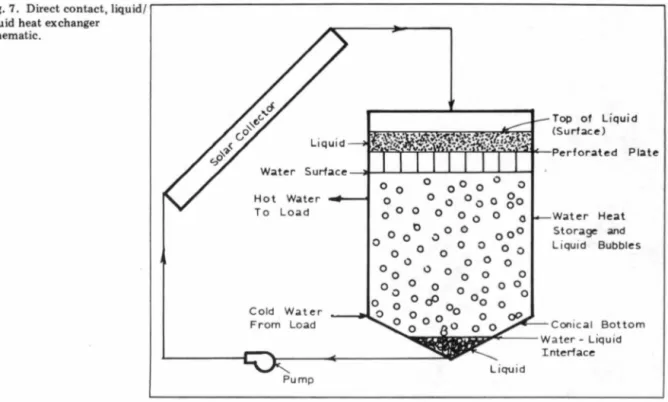
Fig. 7. Direct contact, liquid/ liquid heat exchanger schematic. Hot Water To Load Cold Water From Load Pump
possibility. Presently available cooling units (e.g. lithium bromide absorption cooling machines) utilize water to deliver the input energy to run the cooling unit.
Water as a thermal storage medium is perhaps the most common form of energy storage. Its ready abundance and low cost combine with long experience with water systems to make it a natural choice. Numerous other fluids with possibly more desirable heat transfer characteristics are available, but only at higher cost and potentially with undesirable characteristics (toxicity, etc.).
Considerable research has been devoted toward the utilization of phase change materials such as Glauber's salts, for the storage of thermal energy. These materials usually involve difficulties in corrosion of the storage container, and in eventual stratification of the salt and water. More significantly, the only real advantage of phase change
th~rmal storage is in a lower volume of material required
for a specific amount of energy storage. However, a solar heating and cooling system would only require a thermal storage volume of 1.5 - 2.5 gal of water per square foot of solar collector area. Thus a typical house of 2500 sq ft floor space with a 600 sq ft collector would only need about 1200 gal of water for its thermal storage needs. Any increases in this size are economically not justified. Thus, the advantage of a lower storage volume is, in general, not sufficient to justify the expense and trouble.
The only disadvantage concerned with water as a thermal storage medium is the use of water in the solar collector, where concerns of corrosion and /or freezing are significant. In general, this problem is solved by isolating the fluid in the collector loop from the thermal storage fluid, by use of a heat exchanger. This allows the use of ethylene glycol and corrosion inhibitors in the collector
0 0 0 0 0 0 0 0 0 0 0 0 0 0 0 0 0 0 0 0 0
o go
0 t> 0 0 0 0 00 0 0 0 0 0 0 oOO 0 0 0 0 0 0 0 0 0 0 0 O c;P 0 0 Oo 0 00 0 0 0 0 0 Liquid Top of Liqu id (Surface ) Wa t er Hea t Storage and Liquid BubblesConical Bot tom
loop without the expense of these additives in the storage volume. It also allows for the use of high boiling point/low freezing point fluids in the collector loop, where requirements for only 20-30 gal do not represent prohibitive· costs. The use of high boiling point ("" 600° F) fluids is even more important when one considers the high performance collectors already discussed and the inevitability of power failures to the pumps required to move the heat transfer fluid through the collector loop.
The disadvantages of the typical heat exchanger are the additional cost and the temperature difference across the exchanger. The ti.T is significant since for a specific operating temperature of the thermal storage, the solar collector must operate at about 10°C higher temperature, where the collector efficiency is less. This can be very important in cooling systems where the minimum thermal storage temperature to operate the cooling unit may be 90-95°C (194-203° F). The ti.T across the heat exchanger may have very significant effects on the percentage of the cooling load carried by solar.
One particularly innovative idea, originally proposed by G.O.G. LOf, and investigated by J .C. Ward is the use of a direct contact, liquid /liquid heat exchanger. This exchanger uses an immiscible (e.g. butyl benzyl phthalate, cresyl diphenyl phosphate, Therminol 55) liquid in the solar collector (with low freezing and high boiling points) which has direct transfer with water in the thermal storage unit. A prinicipal requirement is that the immiscible liquid be substantially different in density from water in order to maintain stratification of the liquid and the storage water. Figure 7 shows a schematic of the direct contact, liquid /liquid heat exchanger. In this case the liquid is heavier than · water and when received from the solar
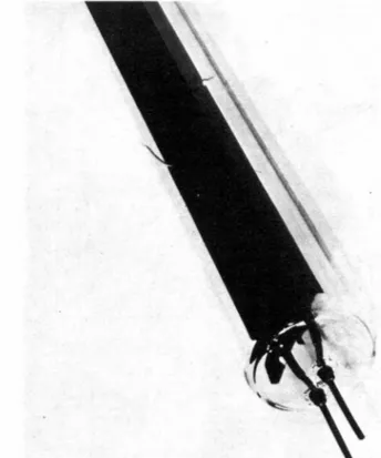
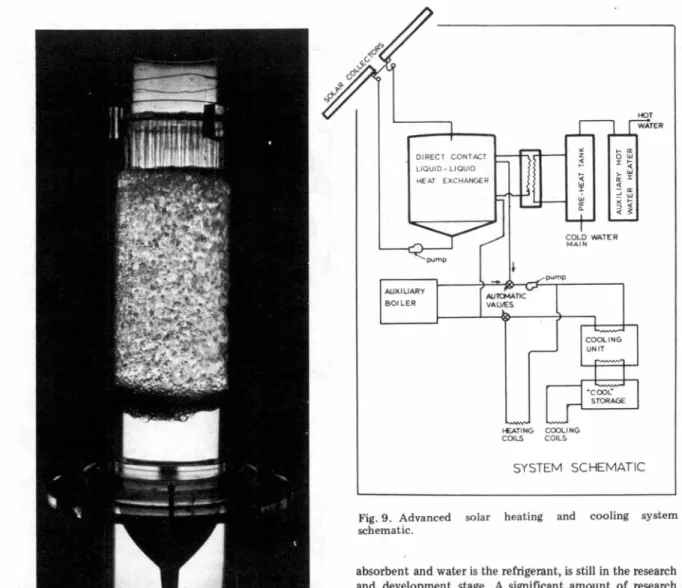
Fig. 8. Direct contact, liquid/liquid heat exchanger test model.
collector falls through the water and provides for direct contact heat exchange with the water.
Figure 8 is a photograph of an actual test module in operation with the immiscible liquid shown by the dark bolor. Several noncorrosive, high boiling point fluids have already been investigated and substantially confirm the feasibility of the concept.
Heating and cooling systems
Solar heating systems are generally pretty well understood. While numerous improvements, both substantial and minor, can be expected, the basic system designs are now workable. An indication of this point lies in the rapid commercialization of the solar heating field.2
Solar cooling is Jess well understood, and in fact there are no commercial cooling units presently available for use with solar energy. The most likely candidate for residential use, a cooling unit in which lithium bromide is used as the
AUXILIARY SOI LER "' z >-0 ~ r
:.
>-D:"'
"
r ~ ~ .;, D:">-..
~ ~ COLO WATER M A I N ""11CMATIC VALVES pump ~TING COOLING COILS COILS HOT SYSTEM SCHEMATICFig. 9. Advanced solar heating and cooling system schematic.
absorbent and water is the refrigerant, is still in the research and development stage. A significant amount of research and testing has been accomplished , however, and certain. aspects of the cooling unit's operation have been noted.
One of the most noteworthy points is the transient nature of the solar system operation, which has severely limited the steady-state analysis. The cycling of the cooling unit under low demand conditions has , for example, indicated the desirability of a method of storing "cool," as well as the normal "hot," thermal storage component. This and other design modifications can be expected as further development of sotar·heating and cooling systems continue. Figure 9 shows a possible schematic of a solar heating and cooling system utilizing some of the advances discussed in this paper. New ideas and innovations can be expected to modify this design significantly.
Ed. note: See also Matthew Young's note "The greenhouse effect" on page 226.
References
1. E. Speyer, American Society of Mechanical Engineers (ASME), Paper No. 64-WA/Sol-2. [Transactions of ASME, Journal of Engineering for Power.]