Product Development of
Terminal Testing Box (TTB)
Master thesis work
30 credits, Advanced level
Product and Process Development
ERICA VISTI
Report code ABB: 3AST006267 Tutor ABB: Stefan Lindberg Tutor Mdh: Ragnar Tengstrand Examiner: Sten Grahn
ABSTRACT
wenty weeks ago I got the honor to pursue a project for ABB Crane Systems. After success with an innovative direction on their Remote Control Station they wanted a continuation of industrial design in another new product development. The aim was to specify the customer needs and create a concept to a Terminal Test Box (TTB), with hopes to gain momentum and funds for continuation of the project.
The terminals earn their money based on productivity of the quay, meaning that the number of ship-to-shore lifts per minute becomes very important. Clients have requested a solution where they can simulate their cranes to ensure function. At the moment approximately five prototypes have been delivered, for example to Peel Ports in Liverpool and Lazaro Cardenas in Mexico. The current Test box lack a proper casing and user adapted features. Based on interviews with personnel at Crane Systems representing linked/adjacent work with TTB the customer needs was determined to: a solution adapted to commissioning phase, a process panel easy to reach, access to components without exposing them, oversight of components and ability to move TTB. The test box is used either standing on the floor or placed on a table. Placed on the floor the operator must twist and bend to access the box, leading to an unpleasant working posture. Set on the table the box is bulky.
The initial idea development resulted in three potential positions and seven initial concepts. Of these seven three ideas was conceptualized and graded in Pughs matrix. The concept Stand high offered a convenient and ergonomic solution independent of the available interior in commissioning phase. However Stand high had weaknesses where the other two concepts Cross and Transparent showed strengths and therefore the three concepts were combined into one. Knowledge about the included components such as an industrial computer and power supply and their requirements has driven the process.
TTB will be produced in approximately ten units per year. The slim edition made it alluring to look into state of the art manufacturing such as Additive Manufacturing compared to the more traditional use of shielded metal. Possibilities regarding the small series can be used by ABB for continuously trying the product towards the customer and offer a flexible product that can be individually adapted to some extent.
The final concept of TTB is improved compared to the Test box looking at horizontal and vertical spacing between the components, which also enables cable channels. The process panel included has an inclination of 15 degrees to avoid reflections as much as possible and to create an ergonomic working position. It has a see through front door giving access and viewing of the components. A combined CNC and 3D-printing prototype/product from the company HLH in aluminum and Plexiglas would cost approximately 24 750 SEK. Manufacturing in shaped sheet metal at Sweco (without a see through door) would cost approximately 10 000 SEK. This is creating an exciting situation, where the recommendation is to create a prototype to further evaluate the concept into completion.
SAMMANFATTNING
ör tjugo veckor sedan fick jag det hedersamma uppdraget att genomföra en produktutveckling åt ABB Crane Systems. Det kontrollbord som Crane Systems har tagit fram hade då hamnat i rampljuset och bland annat fått designpriset Red Dot. Ett fortsatt arbete med en innovativ inriktning i kombination med industridesign önskades nu för ytterligare en produkt - en Terminal Test Box (TTB). En betydande del av arbetet ägnades åt att hitta kundernas behov för att kunna skapa ett koncept. Detta redovisades med en serie 3D-renderingar, med förhoppning om att väcka intresse och erhålla medel för fortsättning av projektet.
Kranterminaler har efterfrågat en lösning för att simulera kranarna och på så vis säkerställa kranarnas funktioner. Just nu har ungefär fem testlådor levererats, men den nuvarande testlådan saknar användarvänlighet och känslan av en ABB-produkt. Baserat på intervjuer med personal på Crane Systems specificerades följande önskemål gällande TTB: en lösning tillämplig i uppstartsfas, naturlig åtkomst till processpanelen, smidig tillgång till de ingående komponenterna och erhållen feedback från deras dioder samt en flyttbar lösning. Den nuvarande testlådan används antingen stående på golvet eller placerad på ett bord. Placerad på golvet måste operatören vrida och böja sig för att komma åt lådan, vilket leder till en onaturlig arbetsställning.
Den inledande idéutvecklingen resulterade i tre möjliga positioner och sju koncept. Av dessa vidareutvecklades tre idéer och betygsattes i Pughs matris. Konceptet Stand high erbjöd en användarvänlig lösning oberoende av tillgänglig interiör. Däremot hade Stand high svagheter där de andra två koncepten Cross och Transparent visade fördelar och därför kombinerades de tre koncepten till ett. Kunskap om de ingående komponenterna har varit av yttersta vikt för att kunna erbjuda en förbättrad lösning.
TTB kommer att produceras i cirka tio enheter per år. Den lilla upplagan gjorde det lockande att jämföra tillverkning som 3D-printing (AM) jämfört med mer traditionell tillverkning såsom bockning och skärande bearbetning i plåt. Möjligheterna beträffande små serier kan användas av ABB för att kontinuerligt testa produkten gentemot kunden och erbjuda en flexibel produkt som kan terminal-anpassas i viss mån.
Det slutliga TTB-konceptet är förbättrat jämfört med testlådan sett till horisontella och vertikala avstånd mellan komponenterna, vilket även möjliggör för kabelkanaler. Den inkluderade processpanelen har en lutning på 15 grader för att undvika reflektioner och för att skapa en behaglig arbetsställning. En frostad dörr framtill ger översikt och tillgång till komponenterna. En prototyp/färdig produkt från företaget HLH genomförd med CNC och 3D-printad aluminium och plexiglas skulle kosta cirka 24 750 SEK och tillverkning på Sweco (kompakt dörr) skulle kosta ungefär 10 000 SEK. Detta skapar en spännande situation, där rekommendationen är att skapa en prototyp och fortsätta utvärdering av konceptet.
ACKNOWLEDGEMENTS
et me start by telling about some exciting happenings in my life. As a child I draw column meters of paintings and some creations made it to grandma’s refrigerator. In 2006 I went to my first and only audition applying makeup in front of a jury. That took me on a tour through Sweden where my ideas ended up on faces from Malmö to Skellefteå. Recently I stood on SJ's headquarters to present my concept of reflectors for adults. The reflector was then handed out as giveaways to commuters. After reading the Master's Program in Product and Process Development at Mdh I started my thesis at ABB in September 2014. Many of the most exciting happenings I've experienced have to do with design and this wasn’t an exception. The work has been motivating and rewarding and I‘m grateful for the opportunity.
The following people deserve a huge thank for their dedication during the project:
Stefan Lindberg and Markus Christerson at ABB Crane Systems for being my mentors and participants in brainstorming, concept development and sanity checks
Camilla Kullborg at ABB Corporate Research for great inputs and feedback during the project
Henrik Norén, Reine Thyselius, Bo Boytchev, Fredrik Johanson, Clara Holmgren, Peter Almhager, Patrik Gustafsson, Gunnar Welding, Per Wickström and Dan Välitalo at ABB Crane Systems for generously sharing their knowledge and opinions
Anders Thunell at Expectrum for being an objective source of knowledge
Jörgen Andersson and Harri Heikkilä at Sweco for helpful discussions regarding mounting and assembly
Crystal Gong at HLH Prototypes, Robert Mellberg and Leif Kressin at Treo Plåt, Leif Norman at Prototal and Leif Plahn at P. Andersson AB for information regarding manufacturing and prices
And finally a huge thanks to Ragnar Tengstrand and Bengt Erik Gustafsson at Mdh for four and a half year of never ending support, this being the grand finale.
Erica Visti
Västerås January 1st, 2015
CONTENTS
1. INTRODUCTION ... 9
1.1. ABOUT ABB ... 9
1.2. BACKGROUND ... 9
1.3. MDH’S ROLE AND PROJECT AIM ... 10
1.4. PROJECT PRIORITIES ... 11
1.5. CONTINUATION OF THE PROJECT ... 11
1.6. PROBLEM FORMULATION AND UNDERSTANDING ... 12
2. APPROACH AND RESEARCH METHOD ... 13
2.1. QUALITY ASSURANCE ... 13
3. THEORETIC FRAMEWORK ... 14
3.1. DESIGNING ELECTRONIC PACKAGING ... 14
3.1.1. Separating Data and Power ... 15
3.1.2. EMC ... 15
3.1.3. IP-Rating ... 15
3.2. DESIGNING FOR SMALL SERIES ... 16
3.3. MANUFACTURING OF PROTOTYPES OR SMALL SERIES ... 16
3.3.1. AM (Rapid Prototyping and Rapid Manufacturing) ... 16
3.4. DESIGNING FOR OFFICE ENVIRONMENT ... 17
3.4.1. Ergonomics ... 17
3.4.2. Anthropometric Data ... 17
3.4.3. Screen and Lightning ... 18
3.5. DESIGNING FOR ABB IN PARTICULAR WITH THE DESIGN GUIDELINES ... 19
3.6. THE PRODUCT DEVELOPMENT PROCESS ... 20
3.6.1. Gantt-Chart ... 20
3.6.2. Function Diagram ... 20
3.6.3. Requirements Specification ... 20
3.6.4. Pughs Matrix ... 20
3.6.5. Quality Function Deployment (QFD) ... 21
3.6.6. Design for Reliability/Failure Modes and Effects Analysis (FMEA) ... 22
3.6.7. Design for Manufacturing (DFM) ... 22
3.6.8. Design for Assembly (DFA) ... 22
3.6.9. Design for Maintenance (DFMain) ... 23
4. IMPLEMENTATION ... 24
4.1. GANTT-CHART ... 24
4.2. FIELD STUDY ... 24
4.2.1. Business Intelligence and Customer Benefit ... 25
4.2.2. Competitors ... 26
4.2.3. The Operators ... 26
4.2.4. Upcoming Changes and Modifications to Consider ... 28
4.2.5. Included Components in TTB ... 29
4.2.6. Simplified Wiring Diagram ... 33
4.3. FUNCTION ANALYSIS ... 34
4.4. REQUIREMENTS SPECIFICATION ... 35
4.5. ADDITIONAL APPLICATIONS OF TTB ... 37
4.7. INITIAL CONCEPTS -FEEDBACK AND SELECTION... 39 4.8. EXTREMES ... 41 4.9. CONCEPTUALIZATION ... 42 4.10. PUGHS MATRIX ... 44 4.11. QFD ... 44 4.12. RE-THINKING,FMEA ... 45 4.12.1. Wall Mounting ... 45
4.12.2. Socket Strip with Connectors ... 45
4.12.3. Access to Components ... 45
4.12.4. Visibility of components and lights when closed ... 46
4.12.5. Ability to serve and mount process panel ... 46
4.12.6. Mounting plate ... 46
4.12.6. Handles ... 47
4.12.7. Working in Line ... 47
4.13. SANITY CHECK ... 48
4.14. DFM,COMPARISON OF MATERIAL AND MANUFACTURING ... 48
4.14.1. TTB and AM ... 49
4.14.2. TTB and shaped sheet metal (without curved PMMA front door) ... 49
4.15. DFA ... 50
5. RESULT ... 52
5.1.CONSTRUCTION (COMPARED TO ABB GUIDELINES) ... 52
5.2.INITIAL CHOICE OF COMPONENTS ... 53
5.3.THE RANGE ... 54
5.14. NEW ERGONOMIC POSITION ... 55
6. DISCUSSION ... 57
7. CONCLUSIONS AND RECOMMENDATIONS ... 58
8. B IB L IO GR A FY ... 59
9. A PP EN D IC ES ... 64 APPENDIX 1 - GANTT-CHART WEEKS
APPENDIX 2 - GANTT-CHART DAYS APPENDIX 3 - QFD APPENDIX 4 - FMEA APPENDIX 5 - DFA APPENDIX 6 - QUOTATION HLH APPENDIX 7 - DRAWINGS APPENDIX 8 - COMPONENTS
APPENDIX 9 - PRESENTATION OF 3D-RENDERINGS APPENDIX 10 - FUNCTION TESTING EQUIPMENT APPENDIX 11 - DICTIONARY
FIGURES
FIGURE 1–STS(ORYX SIMULATIONS, N.D.)... 10
FIGURE 2-ARMG(KONECRANES,2014) ... 11
FIGURE 3-COMPLETE TEST CHAIN ... 12
FIGURE 4-SIMULATION OF ENGINES AND SPREADER ... 12
FIGURE 5-IP AND THE VARIOUS MEANINGS DEPENDING ON RATING (ROBOTIQ, N.D.). ... 15
FIGURE 6-ANTHROPOMETRIC ILLUSTRATIONS (ERGONOMICS FOR SCHOOL, N.D.) ... 17
FIGURE 7COLORS OF ABB(ABB,2014) ... 19
FIGURE 8–HOUSE OF QUALITY ... 21
FIGURE 9–CURRENT TEST BOX ... 24
FIGURE 10–RELATIONS BETWEEN ABB AND EU ... 25
FIGURE 11-WORKING STATION WITH RCS ... 27
FIGURE 12-APPROACH WHEN WORKING WITH THE TEST BOX (GRABCAD,2014) ... 27
FIGURE 13–UPCOMING CHANGES ... 28
FIGURE 14– CAD OF CMS(HONG,2014) ... 29
FIGURE 15–IMAGE OF PM595 ... 29
FIGURE 16–SIMPLIFIED CAD OF HW-LOCK ... 30
FIGURE 17–CAD OF QUINT(PHOENIX CONTACT,2014) ... 30
FIGURE 18–CAD OF PROFINET GATEWAY (STIGELL,2014) ... 30
FIGURE 19-CAD OF WESTERMO INDUSTRIAL SWITCH (WESTERMO,2014) ... 31
FIGURE 20–CAD OF ABBMCB(ABB,2014) ... 31
FIGURE 21–SIMPLIFIED CAD OF ABBXCC ... 31
FIGURE 22-CAD OF ABBCP651-WEB-X ... 32
FIGURE 23–CAD OF SCHURTER (SCHURTER, N.D.) ... 32
FIGURE 24–A VISUAL WIRING DIAGRAM... 33
FIGURE 25–FUNCTION ANALYSIS OF TTB ... 34
FIGURE 26–CMS PORTS (NEXCOM,2011) ... 35
FIGURE 27–SOLUTION FOR MTU ... 37
FIGURE 28–TTB IN THE OFFICE ... 38
FIGURE 29–CONCEPTS 1 TO 4 INCLUDING SELECTION ... 39
FIGURE 30–CONCEPTS 5 TO 7 INCLUDING SELECTION ... 40
FIGURE 31–STACKING COMPONENTS ... 41
FIGURE 32-CROSS ... 42
FIGURE 33–TRANSPARENT ... 42
FIGURE 34–THREE VERSIONS OF STAND HIGH ... 43
FIGURE 35–CONCEPT WITH WALL MOUNTING ... 45
FIGURE 36–STAND HIGH WITH CUTOUT, HANDLE AND A COVER WITH SCREWS ... 45
FIGURE 37–PROCESS PANEL AND FASTENERS INSIDE TTB ... 46
FIGURE 38–BUILT IN HANDLE ... 47
FIGURE 39-WORKING IN LINE ... 47
FIGURE 40-CONCEPT FOR SANITY CHECK ... 48
FIGURE 41–SANDBLASTED PMMA ... 49
FIGURE 42-FIXING SCREW ... 51
FIGURE 43–DESIGN CONCEPT TTB ... 52
FIGURE 44–TTB FINAL CONCEPT ... 53
FIGURE 45–RCS AND TTB ... 54
FIGURE 46–MOUNTING PLATE AND PROCESS PANEL ... 55
FIGURE 47-APPROACH WHEN WORKING WITH TTB(GRABCAD,2014) ... 55
TABLES
TABLE 1-ABBREVIATIONS ... 8
TABLE 2–ANTHROPOMETRIC DATA (ERGONOMICS FOR SCHOOL, N.D.) ... 18
TABLE 3–PUGHS MATRIX ... 44
ABBREVIATIONS
bbreviations listed in alphabetical order in Table 1. Table 1 - Abbreviations
A
Abbreviation Full termAM Additive Manufacturing
ARMG Automatic Rail Mounted Gantry
CMS Crane Maintenance Station
CS Control System
DFM Design For Manufacturing
DIN Deutsches Institut für Normung
EMC Electromagnetic Compatibility
EU End User
FAT Factory Acceptance Test
FEA Finite Element Analysis
I/O Input/Output
IDT Academy for Innovation, Design and Technique
IP Ingress Protection
ISO International Organization for Standardization
LVD Low Voltage Directive
MCB Miniature Circuit Breaker
Mdh Mälardalens högskola
MTU Maintenance Training Unit
NPD New Product Design (New Product Development)
OCS Operational Control System
OEM Original Equipment Manufacturer
PLC Programmable Logic Controller
PMMA Polymethylmethacrylate
QC Quay Cranes
RCS Remote Control Station
STS Ship-to-Shore cranes
TEU Twenty-foot Equivalent Unit
9
1. INTRODUCTION
ecently ABB AB won a Red Dot Award for their Remote Control Station (RCS) which is an automatic system for crane terminals. It was rewarded because it significantly improves the productivity and working environment for crane operators. ABB’s work regarding the “Operator in focus” continues, for example with this thesis.
1.1. About ABB
ABB is a global leader in power and automation technologies. ABB operates in approximately 100 countries and the business is built of five divisions based on the industries they serve. They are particularly proud of its record for innovation - some of the technologies we take for granted today were developed or commercialized by ABB. Today ABB is the largest supplier of industrial motors and drives, the largest provider of generators to the wind industry and the largest supplier of power grids in the world (ABB, 2014).
ABB Crane Systems is part of the division Process Automation.The main focus of this division is to provide customers with products and solutions for instrumentation, automation and optimization of industrial processes. Key customer benefits include improved asset productivity and energy savings. Crane Systems assists ports and shipping companies to transfer containers in a reliable and quick way. They are specialized in advanced automation and information systems for motion control of all types of container cranes, which make them a leading supplier of crane systems worldwide. Consequently they supply a large number of systems in Europe, Asia and North America (ABB, 2014).
1.2. Background
The container terminal involves a large number of vehicles and personnel with various tasks. For the terminal to be safe and efficient ABB provides various solutions and crane operator training (ABB, 2005). Markus Christerson who is manager of hardware describes the working environment where some cranes are 100 % automatic while others are semi-automatic. For example landing of the crane spreader may require manual maneuver due to security because of personnel operating nearby. Clients have requested a solution where they can simulate Quay Cranes (QC), also called Ship-To-Shore cranes (STS) and Auto Rail Mounted Gantry cranes (ARMG) operating ashore (see Figure 1 and 2). In order to do this a crane simulation box is necessary, either used individual in start-up phase or later on in combination with the RCS-table. At the moment approximately five prototypes are used, for example in Peel Ports (Liverpool) and Lazaro Cardenas (Mexico). Not all of these are yet started up and running (Christerson, 2014).
10
Figure 1 - STS (Oryx simulations, n.d.)
1.3. Mdh’s Role and Project Aim
Mdh represented by me, Erica Visti, and my role in this project is to study an innovative direction for an interface Terminal Test Box (TTB) evaluating the Terminal Operating System (TOS). Focus is to examine needs from the operators and create a casing, assuming that the included components remain as they are today. The aspiration is to capture ABB look and feel, using a design idiom that creates recognition without logo. An expression of reliability is important. The concept presented will be based on ideas for manufacturing of very low production volumes, as agreed with ABB. The aim is to conceptualize and develop the TTB-design as a first step toward implementation by gaining momentum. This will be presented as a design concept with a series of 3D-renderings. The use of design is meant to continue the changes started with the RCS tabletop panel and to receive funds.
The project is performed with the following measurable goals in mind: o Equivalent or improved environment for included components o Better access to all necessary ports (such as USB)
o An ergonomic solution for the operator
11
1.4. Project Priorities
Priority will be to examine the users’ needs and to evaluate different concepts. There are difficulties in the project most of all regarding slim foundation of practice of the product and competitors to analyze. There aren’t any real competitors or relevant adjacent products to study which complicates for example Quality Function Deployment (QFD). However a QFD can be useful anyhow. Participant observation is slim since existing prototypes are located abroad and without process panel. The situation has therefore been simulated. The small series manufacturing is a difficulty and a possibility; the slim edition doesn’t make it adequate for mass production which results in choice of manufacturing suited for occasional products. Design for Manufacturing (DFM) will be executed but might be inappropriate for this project. Therefore a study regarding small series manufacturing will be done. That includes state of the art methods in this area - rapid prototyping. Respect to assembly will be done to favor maintenance and ease of use as well. These aspects being more important, since assembly isn’t a significant part of the product cost. The absence of competitors is a possibility as well; the product will be unique in the sector.
Further priorities can be found in the Requirements Specification in section 4.4. Underlying to the priorities are ABB directions and guidelines and the above mentioned possibilities and difficulties.
1.5. Continuation of the Project
The terminal in Liverpool was the first one getting a Test box with a process panel in late end of 2014. They will now be able to program buttons and interact with the system. This gives a broader base for continuation regarding customer needs. For further follow-up, see Recommendations in section 7.
12
1.6. Problem Formulation and Understanding
Technology within the TTB is already working, but the solution doesn’t have a proper casing. TTB should be connected to an Operational Control System (OCS) and used during commissioning phase and during subsequent testing. It will enable:
o Ability to simulate all aspects of Quay Cranes (QC) Control System (CS) o Ability to simulate all Programmable Logic Controller (PLC) conditions o Ability to inject all PLC errors
o Ability to create and run automated scripts
Figure 3 is showing the complete test chain during start-up, from test of interfaces to delivery to End User (EU). The aim is to test the right things at the right time.
Figure 3 - Complete test chain
Testing of TOS with TTB takes place in the second and/or third step, Factory Acceptance Test (FAT), of the step chain (Johanson, 2014).
TTB need the same components as the actual crane in order to model the situation. The simulation is working as an animated view identical to the views when operating in reality, showing on a connected computer screen. The PLC makes it possible to simulate engines and spreader, see Figure 4, showing movements but not speed (Norén, 2014).
Figure 4 - Simulation of engines and spreader Interface test
using PC crane emulator
Interface test using crane black
box
Factory Acceptance Test
incl. RCS
Basic function test at building site
Terminal simulation test
incl. Crane Simulators
End user site
PLC
13
2. APPROACH AND RESEARCH METHOD
ubjective methods are the base in in this project which is mainly composed of unstructured interviews, observations and user studies. However objective methods such as ergonomic measurement have been used as well, resulting in a subjective method with objective character. Both secondary data and field work has been used, again a fusion. The methodology adopted in this study included:
1) A field study conducted at ABB Crane Systems. A selection of 10 company employees has been interviewed representing linked/adjacent work with TTB. The number was revised up to 13 persons during the project. Of these 12 persons are working at Crane Systems and one at Corporate Research. External interviews have been done with personnel from Sweco and Expectrum among others. The interviews consisted of open-ended questions to provide qualitative data. Parallel to this minor user studies were performed.
2) A literature study to prepare guidelines to be used for designing concepts. Material regarding electronic packaging, small series, ergonomics and office environment was sought. Beyond this material from ABB provided additional guidelines. An important source has also been manuals on the included components.
3) Product development based on work methods advocated for CKE20 at Mdh. The project structure used is inspired by Karl T. Ulrich and Steven D. Eppinger with their book Product Design and Development (Ulrich & Eppinger, 2012) and David G. Ullman and his book The Mechanical Design Process (Ullman, 2010). Techniques used to determine customer requirements, technical specifications, develop concepts to evaluate and continue developing a concept into a refined product suggestion.
4) Conduct the project within a time frame of 20 weeks (800 hours) where evaluation of the concept is done throughout the time.
2.1. Quality Assurance
Literature and reports have been chosen with consideration to authenticity. Most sources used have been regulated with the attempt to control that the publications and facts presented are mentioned in more than one platform. Foremost recent research has been used since product development is moving fast. Independence and the search for authors who aren’t biased is conducted but with reservation. The Quality Assurance regarding the field study included sanity checks to process information at several levels.
14
3.
THEORETIC FRAMEWORK
his section presents results of the literature study and interviews conducted throughout the project. It was done to gain knowledge in problem areas and to ensure a satisfactory work process. Note the difference between electronic design (construction) and the creating of a product meant for direct use (design). Nevertheless the final product is dependent on its interior and the components formation, wherefore they are strongly connected.
3.1. Designing Electronic Packaging
Due to an exploding market electronic packaging is one of the fastest changing areas of technology. Demands in almost all areas, from home electronics and computing to the large power industry, has made the commerce change rapidly. Yong Liu and Dan Kinzer establish that new materials, modeling and use of Finite Element Analysis (FEA) are tools to use in order to bein the front of the development. Materially they mean that upgraded materials that provide good electrical performance will be essential in the progress.
“Along with new power packaging development, modeling is a key to assure successful package design” (Liu & Kinzer, 2011).
In another study Harri Eskelinen questions the traditional design process of electronic systems consisting of four main stages: system design, electronic design, mechanical design, and Design for Manufacturing (DFM). He calls for development of the design methodology itself instead of developing the four independent design stages. Following is to be read regarding electronic packaging:
“Two basic questionnaires are necessary: first, we need a questionnaire for helping to form the requirement list of each electronic component that is part of the electronic system;
second, the practical manufacturing technologies (possible mechanical geometries, tolerances, surface properties, etc.) must be adjusted with the functional and performance
requirements of each electronic component of the system.Finally, we need understanding to
change the electrical requirements into the mechanical properties”… (Eskelinen, 2001).
Eskelinen also mentions that it’s common that the practical manufacturability aspects often are forgotten. Interaction between electronic and mechanical design makes it possible to consider manufacturability during early design stages. However, in practice the designer should have enough knowledge both in electronic and mechanical design to draw the necessary conclusions (Eskelinen, 2001).
15
It’s unusual to place the components and design thereafter, because it’s more challenging – normally you create a design and place the components in it (Gustafsson, 2014). When designing electronic, or a casing for it, there are some policies to take into particular account.
3.1.1. Separating Data and Power
Research Engineer Anders Thunell at Expectrum advocates a separation between data and power. Working with electronic components where wires from both data and power are connected side by side it’s important to know that parting is eligible (Thunell, 2014). Production Manager Jörgen Andersson working at Sweco agrees and recommends cable channels for doing this (Andersson, 2014).
3.1.2. EMC
Electromagnetic Compatibility (EMC) is the ability of equipment to function satisfactorily in its environment without causing intolerable electromagnetic disturbances to other equipment. Whether it’s electromagnetic interference of conducted or radiated coupling the product must be designed, produced and tested not to interfere equipment or human health. Thunell emphasizes that combining various components, even components that are individually EMC-marked and tested, might necessitate a new testing (Thunell, 2014).
3.1.3. IP-Rating
Ingress Protection (IP) shows the armatures resistance towards intrusion of water and solid foreign objects. The first digit indicates resistance to solid objects (e.g. dust) and the second resistance to water, as exampled in Figure 5. Electronic equipment intended to operate in difficult environments requires good enclosure while indoor equipment doesn’t normally necessitate an IP equally tough; a standard interior armature is generally IP 20. IP-rating testing is carried out in accordance with global standard IEC 60529, its European equivalent EN 60529 or Swedish Standard SS EN 60529 (Sveriges Tekniska Forskningsinstitut, u.å.).
16
3.2. Designing for Small Series
There is a continuing need to increase competitiveness in the design chain. Engineers must focus in reduction regarding a number of factors: product development time, engineering change costs and pilot run time
.
Small series offers flexibility and a study by Chen-Fang Tsai, Anne James and Weidong Li raises just flexibility of New Product Design (NPD) for small series production. They recommend postponement design to reach a quick response and cost effectiveness. NPD provides possibilities designers can use to determine product specifications, customer needs and marketing goals. Small series in NPD can be a pre-simulation procedure to find the right product functions and reach market acceptance. Benefits with small series production are possibilities to reach the varieties of lot sizes with the optimal efficiency at any demand and different product functions (Tsai, James, & Li, 2010).3.3. Manufacturing of Prototypes or Small Series
Beside a valuable design strategy the choice of manufacturing for small series is both limited and full of potential. Impracticability of special tools isn’t longer a hinder if Additive Manufacturing (AM) can become economically justifiable. Later a comparison of traditional state of practice such as shaped sheet metal will be compared to AM.
3.3.1. AM (Rapid Prototyping and Rapid Manufacturing)
AM is used for rapid prototyping in product development but also increasingly for rapid manufacturing, meaning production of final parts (Bártolo, 2014, p. 37). The method hasn’t yet reached the great mass, but AM competitiveness is improving. Movements that point towards that AM will lead to an industrial transformation are decentralization of production and increasing demands on customization. Reduction of both transaction and delivery costs due to closeness to the customer are other signs (Wohler, Terry et al., 2013, p. 177).
Wohlers Report point out that AM is mostly used in industries involving consumer products/electronics while less used in industrial/business machines. A chart showing the cumulative industrial AM systems installed in various countries shows that Sweden is placed last comparing 14 countries, even though 2012 was a strong year for AM here. The trend is toward direct part production and automation, where customers are more focused on the value of the parts rather than fabrication method.
Advantages
AM parts are generally performed in a single step while most conventional manufacturing require multiple stages. The more features you have in your design these stages can increase dramatically. AM can be seen as an effective way to predict the time it will take to fabricate the model, regardless of changes during the designing stage (Gibson, Rosen, & Stucker, 2010, p. 9).
AM enable creation of models and “models are nearly always required in the end to fully validate the design” (Gibson, Rosen, & Stucker, 2010, p. 3).
17
Disadvantages
Limitations around materials, quality, standards (tolerances) and costs. But also lack of knowledge (Bártolo, 2014, p. 37). Regarding the diverse way of thinking when constructing for AM in CAD the knowledge in Sweden is low according toEngineering Technician Bengt Erik Gustafsson (Gustafsson B. E., 2014). This could of course be a great advantage for companies’ cutting edge.
3.4. Designing for Office Environment
Since the work on the terminals principally has been redirected from an in crane environment to an office environment the design as well must adjust. Development engineer Camilla Kullborg describes a shift in staff with the office environment being women dominated while crane operators often are men (Kullborg, 2014). In order to create a healthy office environment with satisfied employees, products in the control room must meet demands on ergonomics, user friendliness and customer benefits.
3.4.1. Ergonomics
In their study Ashraf Shikdar, Mahammad Khadem and Salim Al-Harthy show a strong correlation between the design of a workplace and productivity and health of employees. It’s known that inadequate design contributes to discomfort and injury but more undiscovered that it even leads tofatigue and low performance.The use of anthropometric data for designing office products is the key to improve performance and satisfaction. Given the right office equipment personnel can be healthier and more productive. There are indications that the facilities should be combined withergonomic training for optimal effect. However employees who receive ergonomic products alone still have significantly less complaints compared to employees who don’t receive adapted products (Shikda, Khadem, & Al-Harthy, 2008). Companies buying ABB’s system are responsible for potential ergonomic training for their operators, but ABB contributes with smart products.
3.4.2. Anthropometric Data
Most dimensions of the human body are distributed across a population, which allows the share-out of a dimension to be described with measurements of 5th, 50th or 95th percentile.
Figure 6 - Anthropometric illustrations (Ergonomics for School, n.d.)
The 5th percentiles are the smallest individuals and the 95th percentiles are the largest. When handed a design task you can use available literature data or seek your own. This is entirely dependent on who’ll use the products. There are data for large population groups; International Organization for Standardization (ISO) and also German industry standard Deutsches Institut für Normung (DIN). If the 50th percentiles are construction funding it’s design for the average individual (Hägg, Ericson, & Odenrick, 2010, ss. 170-178).
18
By summing B and F, see Figure 6, from Table 2 shoulder height from the floor is perceived: 1035 mm for males and 955 mm for females. Summing F and G gives elbow height from the floor: 678 mm for males and 638 mm for females (Hägg, Ericson, & Odenrick, 2010, s. 174).
Table 2 - Anthropometric data (Ergonomics for School, n.d.)
Anthropometric estimates for British adults [mm]
Dimension 5th % 50th % 95th %
B Sitting shoulder height Male 540 595 645
Female 505 555 610
F Popliteal height Male 395 440 490
Female 355 400 445
G Sitting elbow height Male 195 238 292
Female 192 238 285
3.4.3. Screen and Lightning
Incorrectly placed light sources result in reflections in the screen. Primarily, this is what should guide the placement of the screen and light sources. The screen should be tiltable to avoid reflections from the room's lighting (Hägg, Ericson, & Odenrick, 2010). Avoid having other shiny surfaces in the workplace because even reflexes from keyboard and tabletop threaten to cause irritation. This means that both the keyboard and tabletop should be mat (Musarm, n.d.).
19
3.5. Designing for ABB in Particular with the Design Guidelines
ABB seeks for a specific view on industrial design, which nevertheless leaves enough space for special product and country-specific features. Previous ABB has used general Product Design Guidelines (ABB group, 2014) in combination with individual guidelines for each division. However the company is becoming more industrial design orientated, where one example is the design of the RCS control table. This is partly a result sprouting from the mentioned changes in the working environment and changed conditions. The general guidelines were therefore updated in end of November 2014. Kullborg defines the ABB-design as more square than round, but with ergonomics in mind (Kullborg, 2014).
The General Product Guideline specifies o Shapes:
The use of primary, rectangular shapes conveys simplicity and solidity.Components such as switches, connectors etc. should be arranged simply and logically. The user interface area is the key area and should be the clear focal point of the design. The interface area should be clearly visible and simple to use. The display should be positioned above the half-way line (ABB, 2014).
o Colors:
Primary color RAL7035 (equivalent RGB; 209, 206, 198) Secondary color RAL 7012 (equivalent RGB; 68, 79, 81)
Logo color Pantone 032C (equivalent RGB; 239, 51, 64) according to Product Design Guidelines (ABB group, 2014).
As well as the RCS added white HPL, Tabletop body NCS S 1000-N, NCS6500-N and NCS8000-N (Kullborg, 2014). The colors are presented in Figure 7.
Figure 7 - Colors of ABB (ABB, 2014) o Logo:
The ABB logo shall stand alone to communicate effectively. It must be surrounded by a defined space, separating it from other design elements. The minimum height is 4 mm. The logo should normally be aligned top left and placed on a light grey background (RAL7035) (ABB group, 2014). However the RCS has it on white background aligned to the right and to harmonize TTB will have that as well.
The product identity and design should be Innovative, Robust and reliable, Simple and Sustainable. CAD has been executed according to Product Design Guidelines and User Guide, Consultant Manual and Methodology for Consulting set by ABB.
20
3.6. The Product Development Process
Selected tools from the previous mentioned booksProduct Design and Development and The Mechanical Design Process are briefly described below. If unaccustomed with the tools read through for a quick review and for fuller descriptions please read referred literature.
3.6.1. Gantt-Chart
Gantt is a planning tool where activities and milestones in a project are being documented in an illustrated table, following a timeline. Depending on timeframe the timeline is given in units from days up to years. The set-up of the process being scaled down to precise gates shows at what time tasks are to be solved, and when in relation to each other. Many operations or parts of it can be performed simultaneously (Ullman, 2010, p. 131). The schedule is most effective if used by both managers and employees regarding planning, controlling and operation of the project (Portnell, 2011).
3.6.2. Function Diagram
A function diagram is a method for the product developer to obtain understanding of the product. It defines the core of the product, describing functions of the product (combing a verb and a noun), without describing how it will be achieved. The diagram lists the essential purpose as main function and partial functions. To accomplish the primary function required sub-functions are added. Support functions are desirable for the end user since they add value, but they are not compulsory for the product's performance. One of the most common Function diagrams is a feature tree, where the main feature branch out into sub-functions, and support functions. Conventionally partial functions are linked with solid lines and support functions with dashed lines for distinctiveness (Ulrich & Eppinger, 2012, pp. 122-123).
3.6.3. Requirements Specification
Providing further awareness of the problem the requirements specification is a list of technical measurable values important to the customer and market. The specification provides project goals and core values to all involved shaping the product. Listing these requirements creates a guideline throughout the process, helping to choose between concepts. It creates a deeper understanding for the product and is a perfect quality control in the final phase of the project. A specification consisting of a measure and a value is beneficial, if measurable requirements are possible. The requirement specification shouldn’t be a full manufacturing documentation, but the requirements should be distinct and clear (Ulrich & Eppinger, 2012, p. 73).
3.6.4. Pughs Matrix
Generating concepts result in a number of proposals which need evaluation to reach the most optimal solution. Pughs matrix is a method to find the concepts most suitable for progress. The concepts are listed and ranked against a decided reference concept. The basic alternative scores each concept with either better (+), worse (-) or equivalent (0) compared with the reference concept. The concept with the highest total score when adding up is the solution that best matches the requirements of the final product (Ulrich & Eppinger, 2012). The matrix can also be weighted by giving the different criterions shares of 100 % showing how valuable the criterion is.How well the concepts meet these criterions can be measured with a scale, for example 1-5 or again with (+), (-) or (0) (Ulrich & Eppinger, 2012, pp. 134-136).
21
3.6.5. Quality Function Deployment (QFD)
QFD is an established tool to use during the product development process, with purpose to define the problem and translate the customer's needs into measurable values. It gives understanding from different perspectives by inserting data in a matrix called House of Quality (HoQ), illustrated in Figure 8, in the following steps:
Figure 8 - House of Quality
1) Who are the customers? Often there’s more than one. For example it’s not certain that the customer and the EU is the same person. Identify all customers and users. 2) What do the customers want? Define the product requirements based on as many
perspectives as possible (user, manufacturer, distributor, etc.).
3) Evaluate the importance of each requirement to better determine how much time, money and other resources to spend.
4) How satisfied are customers now? Add competing products, and consider how well they meet market requirements.
5) How will the product requirements be satisfied? Define parameters and measurement so that product requirements can be compared with the target values. 6) Relationship between 2) Product Requirements and 5) Measuring units is identified.
Different symbols or values are given depending on if the relationship is very strong, strong, weak or doesn’t exist at all.
7) Estimates the most important parameters and how well the solutions fulfill them. The product developer should prioritize to satisfy these parameters.
8) Identify the relationship between parameters. Which are connected and which are dependent? This to understand how fulfillment of a particular requirement effects other requirement and thus the final product (Ullman, 2010, pp. 145-169).
22
3.6.6. Design for Reliability/Failure Modes and Effects Analysis (FMEA)
To ensure sustained quality of a product design for reliability is performed. One way to evaluate functioning is FMEA which is a systematic method to predict possible failures which may arise. By analyzing errors and consequences it’s possible to suggest which actions should be executed to prevent errors. FMEA in five steps:
1) Identify the function affected
2) Identify potential failure modes that can occur 3) Identify the effect of failure on the product
4) Identify the failure causes or errors. Organize them in design/manufacturing errors or operational changes
5) Identify the corrective action - recommended action, who’s responsible and what was done.
The steps are noted in a table and used as support and evidence development (Ullman, 2010, pp. 350-353).
3.6.7. Design for Manufacturing (DFM)
DFM highlights the importance of developing products that simplifies manufacturing. This by optimizing all components in the design and use the most appropriate tools and manufacturing methods (Ullman, 2010, pp. 328-329). The simpler the design, the easier and cheaper it becomes to manufacture. The tool is suited for large production volumes and expensive products. DFM is time consuming and might require a cross-functional team, but it can lower costs and met customer requirements in a better way. The manufacturing process should be analyzed thus optimize the design of the product in a cost efficient way (Ulrich & Eppinger, 2012, pp. 253-287).
3.6.8. Design for Assembly (DFA)
DFA is performed to optimize the mounting for a new product. It can advantageously be used for products with many components and a comprehensive installation, in those cases DFA is an important tool. However “DFA is important only if assembly is a significant part of the product cost”. DFA in 13 steps to consider:
1) Overall part count minimized 2) Minimum use of separate fasteners
3) Base part with fixturing features (locating surfaces and holes) 4) Repositioning required during assembly sequence
5) Assembly sequence efficiency
6) Characteristics that complicate handling (tangling, flexibility) have been avoided 7) Parts have been designed for a specific feed approach (bulk, strip, magazine) 8) Parts with end-to-end symmetry
9) Parts with symmetry about the axis of insertion
10) Where symmetry is not possible, parts are clearly asymmetric 11) Straight-line motions of assembly
12) Chamfers and features that facilitate insertion and self-alignment 13) Maximum part accessibility (Ullman, 2010, pp. 329-349).
23
3.6.9. Design for Maintenance (DFMain)
By ensuring maintenance the life of the product is extended. DFMain contributes to a way of thinking where it should be easy to diagnose a problem and repair it. It proposes that components can be easily replaced and easy to disassemble (Ullman, 2010, pp. 357-358). Some important guidelines for working with DFMain are:
o Use standard, universally applicable components o Use fasteners that accelerate maintenance activities
o Provide sufficient space around the maintenance points (Mulder, Basten, Jauregui Becker, Blok, & Hoekstra, 2014).
Proceeds from theoretic framework:
o Understand the included components as well as possible; form requirements of each component that adjust the functional design
o Strive for interaction between electronic and mechanical design o Separate data and power
o Benefit from small series to reach optimal efficiency at any demand and different product functions
o Modeling and use of FEA is beneficial
Agreement with importance of modeling to validate the design influenced the work. It led to a quest for an initial choice of components performed to achieve a final result prepared for a quick making of a prototype, even though some features still have to be adjusted.
24
4. IMPLEMENTATION
he applied methodology in this project is described in this section.
4.1. Gantt-Chart
Two Gantt-charts was used to plan and monitor the project. One Microsoft excel-chart with a timeline built of days, weeks and months and one simplified built of weeks and months. The first one was perceived hard to overview; therefore a second one for controlling of the project was done since the schedule is most effective if used by both managers and employees (Portnell, 2011). The other one became important only for personal use. Gantt-charts can be found in Appendix 1 and 2.
4.2. Field Study
The ships coming into harbor has continuously increased in size and the largest ship today loads over 18.000 Twenty-foot Equivalent Unit (TEU) (Christerson, 2014). Area Sales Manager Clara Holmgren mention the high demands on the terminals logistic-system that sometimes leads to productivity lower than wanted. The income is based on productivity of the quay, meaning that the efficiency is based on number of STS lifts per minute (Holmgren, 2014).
Terminals have asked for a box where they can test the interface to the TOS and new software features (Strömberg, 2014). Figure 9 shows the current Test box (called both TOS box, FAT-box, Test Harness and Crane Simulation Box) for ARMG sent to Lazaro Cardenas. The box has been delivered in a box from ProDJuser with external dimensions (without cap) of 400 x 490 x 536 mm and a weight of 16.1 kg. The price is 2190 SEK (JP Disco, n.d.). This is how the Test box is described to customers:
Figure 9 - Current Test box
T
“Used during FAT for testing of the crane control software towards third party hardware and software such as TOS… …This will help minimize the commissioning on site since communication protocols and some function test can be tested in advance. After commissioning the FAT-box can be used in the same way for testing software in a safe environment before test them on the cranes and impact production. The Test Harness consists of same type PLC and CMS computer to make it as real as possible… …Everything comes in box for easy transportation and storage. The Test Harness has no extra visualization.”
25
4.2.1. Business Intelligence and Customer Benefit
Sales Manager Fredrik Johanson considers ABB market leaders because they offer a concept based on safety, trust and the latest technology. This is enabled by a customer focused organization with experience and the aim to push forward. The market has few actors but despite that it’s relatively hard to earn money. Looking ahead Johanson thinks automation is becoming an even bigger factor. Some of the smaller terminals are having problem with high personnel intensity when bigger ships arrives, making it hard to plan manpower smoothly (Johanson, 2014).
“Even though it’s advanced technology which first and foremost sells visualization of products awakens curiosity” (Johanson, 2014).
Holmgren, in the same way as Johanson, touches the differences between selling a system in comparison to just offering products. She believes that ability to present complete systems is the future: if you can offer the whole solution you’re unique. The clients want a complete solution ready to use. When selling a system where your EU pays a lump sum it’s a good thing to specify for the clients what they get for their money. Otherwise they might choose a lower cost supplier since the benefits aren’t obvious (Holmgren, 2014).
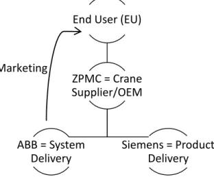
Johanson describes the internal relations between ABB and the EU demonstrated in Figure 10. ABB contracts with a Crane Supplier, for example ZPMC, who is Original Equipment Manufacturer (OEM), offering a System Delivery to EU. All marketing from ABB is directly communicated to EU. In comparison there are companies, such as Siemens, handing Product Delivery. Customer benefits sold are security and confidence to perform the maximum lifts per minute, making the EU willing to pay approximately 7.5 % more for the system contracts than for single products (Johanson, 2014). These internal relations making ZPMC both a customer and a competitor to ABB since the 7.5 % share is desirable.
Figure 10 - Relations between ABB and EU End User (EU)
ZPMC = Crane Supplier/OEM ABB = System Delivery Siemens = Product Delivery Marketing
26
4.2.2. Competitors
There might be similar solutions with components operating to simulate without a shell, but as far as ABB is concerned there aren’t any related solutions or competitive products out on the market. General competitors in the crane-sector are for example ZPMC (ZPMC, 2013), Konecranes (Konecranes, 2014), Kalmar Cargotec (Kalmar, 2014) and Siemens (Siemens, 2014). Mobile charts have been inspirational, for example racks from Middle Atlantic Products (Middle Atlantic Products, 2014).
4.2.3. The Operators
Software developer Henrik Norén describes the user of TTB as IT integrators who confirm the functioning of the crane before launching. TTB is primarily used before the cranes arrive to site and ABB hands over to the customer. He mentions that the solution today offers power inlet and power supply which is a benefit. However you can’t close the box while working since you have a computer screen connected. Also current placing of the CMS hinders using of the USB ports on one side without removal of one wall on the box from ProDJuser. The added process panel will simplify but it also requires consideration of placing so that the process panel is easy to reach and that you have access to it during work. The panel should be somewhat protected since the TTB will be stored (from weeks up to six months) and the screen is unprotected if positioned outwards. Ideal would be if the screen could be separated from the other components and be used specific (Norén, 2014).
“The process panel is a challenge. I’m dreaming here but it would be nice if the panel was flexible and could be moved” (Norén, 2014).
27
Figure 11 - Working station with RCS
“Before RCS came the customers wanted to add or remove features. By offering a complete solution you avoid such demands. The product is set” (Holmgren, 2014).
Illustrations in Figure 12 are showing how the test box is used either standing on the floor or placed on a table. Placed on the floor the operator must twist and bend to access the box, leading to an unpleasant working posture. Set on the table the box is somewhat bulky and this isn’t always possible, depending on which interior is available in start-up phase. The process panel is being used more frequently than other components, leading to a repeated twist and bend-movement (Norén, 2014).
Figure 12 - Approach when working with the Test box (GrabCAD, 2014)
The RCS table shown in Figure 11 consists of an operating desk from CGM (CGM, n.d.) and tabletop panel in vacuum casting plastic made by Prototal (Prototal, n.d.). Area Sales Manager Clara Holmgren involved in the development of RCS in collaboration with No Picnic (No Picnic, n.d.) describes the effort getting the right reliable feeling. She defines ABB as robust and safe; therefore it was important that the joystick didn’t feel like a toy or that the tabletop panel didn’t yield (Holmgren, 2014). TTB will be equipped with the same process panel, as the tabletop panel, going from CP650-WEB-x to CP651-WEB-x.
Since TTB is used early in the projects during commissioning the RCS control table might arrive and be mounted later, therefore it isn’t certain that they will be seen together. However the TTB-solution is still meant to harmonize with RCS control table in line with ABB’s wishes (Lindberg, 2014).
28
4.2.4. Upcoming Changes and Modifications to Consider
The assumption that included components remain as they are today involves research of upcoming changes and modifications close in time. Constructor Per Wickström lists planned changes that affect TTB physical as following, red markings indicate corresponding component in Figure 13:
o Existing TTB contain an ABB Profinet I/O that will be discarded when adding an ABB process panel. First CP650-WEB-x was intended, but this was later revised to CP651. CP650 and CP651 both have a 10.4” display touchscreen, but the depth of CP651 adds 5 mm to CP650s 42 mm. (1)
o Current Industrial Routing Switch from Westermo will transfer from RFI-10-F4G-T4G to RFI-211-F4G-T7G. RFI-10 and RFI-211 are equally sized height and width-wise (choosing the same amount of slots) but RFI-211 is 5 mm slimmer in depth. (2) o ABB PLC; AC500, PM595 isn’t officially launched yet, but will still be construction
founding. PM591 and PM595 are two types of AC500 used in TTB. ARMG is equipped with PM591 while STS will be equipped with PM595, but eventually ARMG will most likely transfer to PM595 as well. Further PM595 is bigger and will accordingly be construction founding,thus both can be used. (3)
o ABB, Crane license key, HW-lock has malfunctions at the moment but looking ahead it’s necessary and must be included. (4)
o Current solution contains a MPC-21 that will be replaced with an ABB XCC/CPS PC/104, TS-TKS-P20-541I-N001 (5) (Wickström, 2014).
Horizontal and vertical distances between the components are slim ornonexistent.
Figure 13 - Upcoming changes
1
2
29
4.2.5. Included Components in TTB
Constructor Reine Thyselius have specified the existing components. An operating temperature is the temperature at which an electrical or mechanical device operates. The device will operate effectively within a specified temperature range. Following components are the ones that the solution is based upon:
Figure 14 - CAD of CMS (Hong, 2014)
Figure 15 - Image of PM595
1) NEXCOM, industrial computer (CMS), NISE 3500
NISE 3500 is an industrial fanless computer designed for
applications which demand intense graphics
performance, in this case industrial automation. The TTB CMS requires ability to connect to DVI-D (screen), LAN (network) and USB 2.0 ports (keyboard, mouse and USB-memory) (Thyselius, 2014).
Weight: 4500 g (own data from weighing)
Operating temperature: -5°C to 55°C (ambient with air flow)
Instructions to take into particular account: The openings on the enclosure are for air convection to protect the equipment from overheating; therefore it’s important not to cover the openings (NEXCOM, 2011).
2) ABB, PLC; AC500, PM595 (DIN)
PM595 (containing two expansion cards), a
Programmable Logic Controller (PLC), which is a digital computer used for automation of electromechanical processes. Devised for advanced forms of automation and complex industrial applications it controls machinery on the cranes. The PLC communicates using one of several possible open or private protocols, such as Profibus.
Weight: 1100 g (own data from weighing)
Operating temperature: 0°C to 60°C, horizontal mounting of modules (ABB, 2014).
30
Figure 16 - Simplified CAD of HW-lock
Figure 17 - CAD of QUINT (Phoenix Contact, 2014)
Figure 18 - CAD of Profinet gateway (Stigell, 2014)
3) ABB, Crane license key, HW-lock (DIN) A license key protecting the hardware.
4) Phoenix, Power supply, QUINT-PS/ 1AC/24DC/10 (DIN) Quint supplies electric energy to an electrical load since the primary function is to convert one form of electrical energy to another.
Weight: 1100 g
Operating temperature: -25°C to 60°C (derating)
Instructions to take into particular account: In order to ensure sufficient convection, Phoenix recommends a minimum vertical distance of 50 mm to other modules. A lateral distance of 5 mm, and in the case of active component, that of 15 mm is necessary for proper functioning of the module. Depending on the ambient temperature and the load of the module, the housing can become very hot (Phoenix Contact, 2014).
5) Phoenix, Profinet gateway safe, FL PN/PN SDIO-2TX/2TX (DIN)
The industrial gateway enables linking between diverse networks and can also be used for controlling overall security features. Profinet is a standard for industrial automation using a computer network, operating Ethernet among others.
Weight: 550 g
Operating temperature: -25°C to 60°C (Phoenix Contact, 2014).
31
Figure 19 - CAD of Westermo Industrial Switch (Westermo, 2014)
Figure 20 - CAD of ABB MCB (ABB, 2014)
Figure 21 – Simplified CAD of ABB XCC
6) Westermo, Industrial Routing Switch, RFI-211-F4G-T7G (DIN and screw)
RFI-211 (two slot enclosure) is a high performance industrial Ethernet switch designed for high network traffic applications.
Weight: 1500 g
Operating temperature: -40°C to 70°C
Instructions to take into particular account: The unit uses convection cooling. To avoid obstructing the airflow around the unit, use the following spacing rules. Minimum spacing 25 mm above/below and 10 mm left/right the unit (Westermo, 2014).
7) 3 x ABB, Mini Circuit Breaker (MCB), S 201-C 4 (DIN) MCB offer a compact solution to protection requirements, since the device is current limiting. TTB requires three MCB.
Weight: 125 g
Operating temperature: -25°C to 55°C (ABB, 2014).
8) ABB, External Communication Central (XCC), TKS-P20-5411 (DIN)
Weight: 500 g
Instructions to take into particular account: XCC has ventilation grilles on top and on the right side. Therefore the right side needs spacing more than the left one (Lindberg, 2014).
32
Figure 22 - CAD of ABB CP651-WEB-x
Figure 23 - CAD of Schurter (Schurter, n.d.) 11) Terminal blocks
Terminal blocks are electrical connectors where the wires are clamped down to the metal part by a screw. The connector allows more than one circuit to connect to another circuit. TTB requires approximately four terminal blocks. The blocks work in combination with 4) Power supply, QUINT-PS/ 1AC/24DC/10 and 7) 3 x Mini Circuit Breaker (MCB), S 201-C 4. They are seen as extras and consequently they aren’t listed to the clients. They are also unaffected by operating temperature and light weighted/easily placed wherefore they will be disregarded.
Information regarding included components comes from Thyselius (Thyselius, 2014).
Information about weight/operating temperatures and particular instructions, see Appendix 8 unless specified.
9) ABB, Process panel, CP651-WEB-x
Operator interface with 10.4” display touchscreen. Weight: 2100 g
Operating temperature: -0°C to 50°C
Instructions to take into particular account: Following are required for a proper installation;
o The borders of the cutout must be flat.
o The cutout for the panel must be of the dimensions indicated in manual (276 x 221 mm)
o Maximum deviation from the plane surface to the cut-out: Ø 0.5 mm
o Thickness of the plate the equipment is mounted: 1.5 mm to 6 mm
10) Schurter, Power inlet, 43-499-29 Weight: 30 g
33
Components marked (DIN) requires mounting on a DIN 35 rail (7.5 mm depth). The rails are needed to satisfy manual requirement and ease assembly as well as maintenance and therefore the solution must enable a DIN-rail (Lindberg, 2014). Note that measurements specified in each component manual are housing dimensions and that DIN-rail and plug-in connectors protrude beyond these measurements. Total weight of included components is 11.805 kg, HW-lock and terminal blocks not included.
4.2.6. Simplified Wiring Diagram
Figure 24 is showing connections between components in a simplified wiring based on wiring diagram 3ASX002911-TCD available on ABB intranet. Since the wiring intends components for ARMG and doesn’t consider upcoming changes and modifications the structure is adapted.
Figure 24 - A visual wiring diagram
Beyond illustrated connections quint power supply attaches to several components. Components marked high voltage consist of 220 V while others consist of a lower voltage of 24 V. Production Manager Jörgen Andersson at Sweco recommend that high voltage components are placed together in order to meet the Low Voltage Directive (LVD) 2006/95/EC and presumed CE-marking (Andersson, 2014). In the continued work ABB need
High voltage Socket strip
(Power outlets of CMS pointing downwards)
34
to create a new, adapted wiring diagram for TTB. The diagram is only used by the manufacturer, not the customer (Thyselius, 2014).
4.3. Function Analysis
Figure 25 shows the function analysis of the project with Create casing as main function.
Figure 25 - Function analysis of TTB
The above Resist outer environment implies that the solution shield the inside components better than the Test box, which is open when operating. The need to connect while closed which will be graded further in Pughs matrix.
Create
casin
g
Provide access
Display process panel Admit connection
Access DVI-D, LAN Access USB/eSATA Access power inlet Allow maintenance/repair
Enclose components
Enable DIN rail Enable cable channels
Simplify usage
Sustain storage Admit movability Satisfy ergonomics
Shield environment
Resist outer environment Last appropriate lifecycle
Communicate ABB
Express reliability Express quality Express innovation
35
4.4. Requirements Specification
This section specifies technical restrictions and requirements for usage. The viewpoints are part requirements and wishes from ABB.
Market requirements
1) Dimensions and design shall provide movability.
2) TTB is intended to be introduced on an international market.
Product requirements
3) Constructed for DIN-rail and preferable cable channels.
4) Provide easy access to NEXCOM, CMS, NISE 3500 DVI-D (screen), LAN (network) and USB-ports (keyboard, mouse and USB-memory). All ports on both sides require access, see Figure 26.
Figure 26 - CMS ports (NexCom, 2011) 5) No coverage of the openings on the enclosure on CMS.
6) Phoenix, Power supply, QUINT should have a vertical distance of 50 mm and a horizontal distance of 15 mm to other modules. Vertical Height (VH) was later revised.
7) Westermo, Industrial Routing Switch, RFI-211 should have a vertical distance of 25 mm and a horizontal distance of 10 mm to other modules. HH was later revised. 8) The cutout for ABB, Process panel, CP651-WEB-x must be 276 x 221 mm. Further the
borders of the cutout must be flat.
9) Provide adequate space for wiring in front of the units. That will also enable usage of both RFI-10 and RFI-211 if wished.
10) Provide a power inlet from Schurter, 43-499-29 or equivalent.
11) Uncomplicated assembly of included components is desirable, in reasonableness to the few products produced and assembled.