Leakage in an
oil pump system
– Analysis and suggested improvements
A case study at Husqvarna AB
Mailing address:
Visiting address:
Phone:
This thesis has been carried out at the School of Engineering, Jönköping University, in the subject area Mechanical Engineering. The authors answer themselves for opinions, conclusions and results.
Examiner: Tim Heikkinen Supervisor: Morteza Poorkiany Scope: 15 credits
Abstract
Abstract
Unintended oil leakage is a problem that occurs in a wide range of products in the forest and gardening sector. Presented as a basis for this thesis is an oil pump system designed to provide lubrication for the chain on a pole saw. In this system, unintended leakage occurs and creates a problem. The purpose and aim of the thesis are to investigate and determine the cause of the leakage and suggest how the problem can be solved. Since the company which sells these pole saws profiles as environmentally conscious it is important to solve the issue.
To fulfill the purpose and aim of the thesis, several tests are set up to investigate the cause of the leakage. When an understanding is reached, the set-based concurrent engineering method is used to generate solutions and increase knowledge of the problem. These concepts were tested, and the outcome and effectiveness documented.
The results are presented and discussed from the process of the thesis. The primary cause of the leakage is credited to an over-pressure building within the oil tank, forcing the oil through the obstructions and out the outlet. Included in the results and discussions are suggested solutions to the problem. Two concepts are included as solutions, as well as suggestions for future work and research of the problem.
Table of content
Table of content
1
Introduction ... 1
1.1 BACKGROUND ... 1
1.2 PROBLEM DESCRIPTION ... 1
1.3 PURPOSE AND AIM ... 2
1.4 DELIMITATIONS ... 2
1.5 DISPOSITION... 2
2
Theoretical framework ... 3
2.1 CONNECTION BETWEEN AIM AND THEORY ... 3
2.2 THEORY 1 ... 3
2.3 THEORY 2 ... 4
3
Method ... 5
3.1 CONNECTION BETWEEN AIM AND METHOD ... 5
3.2 IDENTIFICATION OF CAUSE ... 5
3.2.1 Tests ... 5
3.2.2 Theoretical research ... 5
3.3 DEFINITION AND CLARIFICATION... 5
3.3.1 Function analysis ... 6
3.3.2 System analysis ... 6
3.4 CONCEPT STUDY ... 6
3.4.1 Concept study method ... 6
3.4.2 Generating concepts ... 7
4
Results and implementation ... 8
4.1 TEST FOR DETECTION OF LEAKAGE ... 8
4.1.1 Primary test 1 ... 8
4.1.2 Primary test 2 ... 10
4.1.3 Summary of results of identification of leakage cause ... 11
4.2 DEFINITION RESULTS ... 12
Table of content
4.2.2 System analysis ... 12
4.2.3 Summary of definition results ... 13
4.3 RESULTS OF CONCEPT STUDY ... 13
4.3.1 Results of brainstorming ... 13
4.3.2 Results of selection process ... 13
4.3.3 Test and evaluation of concepts ... 13
4.3.4 Summary of concepts ... 19
4.3.5 Summary of results of generating design concepts ... 20
5
Analysis ... 21
5.1 ANALYSIS OF RESULTS OF AIM 1 ... 21
5.2 ANALYSIS OF RESULTS OF AIM 2 ... 21
5.3 ANALYSIS OF METHOD CHOICE ... 22
5.4 VALIDITY AND RELIABILITY ... 22
6
Discussion and conclusions ... 23
6.1 CONCLUSIONS ... 23
6.1.1 Answer to question 1 of the thesis ... 23
6.1.2 Answer to question 2 of the thesis ... 23
6.2 REFLECTIONS ... 23
6.3 RECOMMENDATIONS ... 23
6.4 FURTHER WORK AND RESEARCH... 24
7
References ... 25
8
Appendices ... 27
8.1 GANTT SCHEDULE ... 27
Introduction
1
Introduction
Described in this chapter is an introduction to the thesis and the basis of its relevance. It contains the background of the problem and what needs to be investigated. The purpose and aim of the thesis describe what is to be accomplished, together with the accompanying delimitations.
1.1 Background
The company Husqvarna is developing battery-powered hand-held products for forest and garden applications. Some products need proper lubrication of cutting equipment during use. The lubrication is achieved by pumping oil from a tank onto the chain.
For the current design and assembly of the oil pump see picture 1 below. The picture and index are taken from an internal spare parts database provided by the company and have been thinned out to only the components relevant for the thesis.
Picture 1 – Exploded view of current system.
For the various pump designs currently available in these products, accidental oil leakage is a problem when the product is not in use. After using the product, oil still leaks out at several locations in the system, even though there have been efforts made by the designers to solve this issue. The leakage is a bottleneck for the product both from the function and appearance point of view.
The company profiles as environmentally conscious in a global perspective [1]. It is important to solve the issue with oil leakage, as they also work to continuously improve the environment in a life-cycle thinking [2].
1.2 Problem description
The company’s main focus with the battery powered products is to have them uphold the same professional quality as the products powered by other fuels. The leakage needs to be eliminated to maintain this reputation for the products.
The pole saw intended for this project is part of a series of battery-powered chainsaws, of which many have a similar problem. After the product has been run, an oil leakage occurs leaving undesired stains and spots. For the user, it may involve problems related to the work environment. The stores that keep the product may also have problems with the work environment as well as the credibility in the sale of the product
.
Introduction
Picture 2 – A Husqvarna pole saw with the current oil pump system [1].
This report is based on the investigation and determination of the cause of the unintended oil leakage. Also, a solution is to be developed to eliminate the leakage. The aim is to make the possible solution general enough to apply it to other products that use the same oil pump system.
1.3 Purpose and aim
The first purpose of this thesis is to determine the cause of the leakage in the oil pump system. The second purpose is to find a solution that minimizes the leakage. The following questions will be answered to fulfill the purpose:
What is the cause for the leakage in the oil pump? How can the leakage be resolved?
1.4 Delimitations
The amount of research and testing performed on other products that belong to the battery series will be limited. The limit includes the comparisons with products of other competing companies.
Research will be limited to identifying the problem and concept development. The limit does not include simulation, manufacturing, cost estimation, etc.
1.5 Disposition
The disposition used in this thesis is recommended by Jönköping University and follows the logical order of the work. The thesis is structured so that each section provides a foundation for the next to build on, leading up to the conclusions.
The theoretical framework contains an accounting of the theories collected in the research and provides a basis on which the answer to the questions of the thesis can be answered. The two theories each handle one of the questions stated in the purpose and aim of the thesis.
The methodology used when applying the theoretical framework into the practical test is described in the method chapter of the thesis. This method accounts for each step in the process from the initial investigations up to testing of solving concepts with theoretical support. Results of the investigations and testing are presented and analyzed in chapter 4 and 5 of the thesis and objectively assessed regarding its validity and reliability. As a conclusion, the results of the thesis are discussed, and recommendation for future research and work is provided in
Theoretical framework
2
Theoretical framework
This chapter provides theoretical support used to answer the questions of the thesis. A complete account of the theories is found in section 2.2 and 2.3 of the thesis. These theories are tied together with the results and analysis to fulfill the purpose of the thesis.
2.1 Connection between aim and theory
Theory 1 and theory 2 in this section provide a theoretical background to the two questions stated in the purpose of the report:
What is the cause for the leakage in the oil pump? How can the leakage be resolved?
Theory 1 provides a theoretical foundation for the possible cause of the leakage in the oil pump and the way the oil reacts to pressure.
Theory 2 contains a theoretical basis for stopping the leakage by explaining how fluids behave.
2.2 Theory 1
Viscosity is a quantitative measure of a fluid’s resistance to flow [5, p. 25]. Due to viscous flow, shear stress appears in fluids [6, p. 31]. But if the fluid is at rest, there is no shear stress [6, p. 31]. The fluid then has the same pressure regardless of direction, and the pressure varies according to depth [4, pp. 22-23].
Pressure is transmitted through fluids [3, p. 10]. If there is a volume change or increase of pressure somewhere inside the system, the fluid will distribute this increase equally throughout the entire system [3, p. 10]. Because of the fluids ability to transmit pressure, it can be assumed that if the pressure is increased in one point of the system the increase is the same at every other point in the system [3, p. 10] [4, p. 22].
The pressure of the fluid always acts perpendicular to the surface of the wall containing it [4, p. 22]. This pressure will increase with the depth of the fluid and act the same no matter what direction [3, p. 34]. This increase in pressure is linear and change according to the hydrostatic equation [3, p. 34] [4, p. 25]. Therefore, the minimum pressure always occurs at the maximum height of the system [3, p. 88]. The depth of the system then determines the pressure difference from the surface [3, pp. 164-165].
The pressure difference in the fluid may be converted from potential energy to kinetic energy and push the oil through the system [3, p. 165]. As the law of conversation of energy applies to all fluids, there is a relationship between the potential energy of the fluid level and the kinetic energy of the flow [4, pp. 56-57]. Increasing the pressure of the fluid can therefore attain sizeable kinetic energy [4, pp. 56-57]. The same way narrowing the flow channel decreases the pressure, and the velocity of the fluid is increased [4, p. 61].
Theoretical framework
2.3 Theory 2
Theory 2 provides a theoretical foundation that can be used in constructing a solution that minimizes the unintended oil leakage.
Liquids can be considered incompressible at low pressures, but at higher pressures, the liquids compressibility can affect the system [3, p. 11] [4, pp. 46-47] [6, p. 42]. Accordingly, the density of a liquid can generally be regarded as a constant, and the analysis of a problem involving liquids is thereby simplified [7, p. 21]. The flow of a liquid is also considered incompressible at lower pressures [6, p. 42]. Viscosity in liquids decreases as its temperature increase [3, p. 16] [4, p. 11]. As the temperature increase, the intermolecular forces pulling the molecules to each other weakens, allowing them to move more freely [3, p. 16] [4, p. 11].
There are two major causes why a fluid starts to move; resultant forces and friction [3, p. 62]. Resultant forces act on fluids when there is a difference in pressure or temperature [3, p. 62]. Some fluids resist motion more than others because they have a higher viscosity [6, pp. 32-33].
Method
3
Method
This chapter provides an understanding of the process used to fulfill the purpose and aim of the thesis. Described in the chapter is the method used to answer the questions of the thesis with supporting references for each methodology.
3.1 Connection between aim and method
To answer the first question of the thesis the cause of the leakage was determined through testing of the oil system and theoretical research. This is described in section 3.2 –
Identification of cause.
Several possible solutions were generated to answer the second question of the thesis, and were tested in turn to determine their effectiveness and potential realization.
Stated in this chapter is the method divided into sections for each step of the process, from identification and definition of the problem to testing of different solutions. Each step of the process is tied back to the original questioning and ultimately leads to finding a solution for the problem.
3.2 Identification of cause
The identification of the cause is the initial research of the problem. The primary testing together with the theoretical research provides a fundamental understanding of why the leakage occurs.
3.2.1
Tests
Several functional tests were set up on the current design of the oil pump system to determine the cause of the leakage. The main objective of the tests is to analyze the current system and the individual function of each component. The purpose of the tests is to determine the disadvantages, deficiencies and improvement opportunities in the current design [8, p. 145]. Both test 1 and 2 are constructed to find out what happens in specific scenarios when leakage occurs. The results of each scenario point to the cause of the leakage and what need to be rectified in the current system [8, p. 149]. This method of analysis requires equipment to recreate realistic scenarios.
3.2.2
Theoretical research
When analyzing the cause, it is necessary to have drafts anchored in theory. These theories have been collected through thorough research of scientific literature. When preparing for the research, a reflection is done over the purpose and questions of the thesis to determine the central theories and subjects. With these determined, the research is initiated, and several databases are used for finding relevant literature. The literature is then read through and compared to the questions of the thesis. All relevant information is collected and compiled in
section 2 – Theoretical framework. Concluding the theoretical research is an evaluation of the
material collected, to determine if the data is sufficient. [7, p. 44]
The same process is used when choosing a relevant method for the entire section 4 - Method.
3.3 Definition and clarification
Clarifying the task and gathering data on the problem offers the possibility to discuss and reflect over the problem situation [9, p. 223] [10, p. 58].
In this pre-study, the oil system is analyzed objectively to prepare an eventual development of an alternate design. Using the different analyzation methods described in detail below an internal requirement is drafted as a basis for potential design development. The specification determines the most functional requirements of what the product is designed to do [8, p. 116].
Method
3.3.1
Function analysis
For a problem to be solved, it is essential to know the primary purpose of the system [8, pp. 31,53] [9, p. 181]. By not focusing too much on the issue from the beginning, only the solutions without limitations, creativity is not constrained [11, p. 42]. The purpose of the function analysis is to analyze the system, determine the functions required and set the system boundary of the new design [12, p. 56].
All functions are divided into three groups: primary, necessary and wanted. The primary function is the reason the component exists [9, p. 181]. The functions that the primary function does not work without are called necessary functions. As well there are the wanted functions, the primary function is not dependent on these, but they increase the overall value of the product. [11, p. 42]
3.3.2
System analysis
The system analysis is constructed to avoid misunderstandings regarding the purpose of the different components of the system. The system analysis shows the existing system with components and functions [12, p. 121] [9, p. 188]. By showing the structure of the problem with the parts and their relationships, a deeper understanding of the whole is achieved [11, p. 46] [9, p. 179].
3.4 Concept study
This section describes the method used to generate solutions and create concepts.
3.4.1
Concept study method
The concept study is carried out according to the set-based concurrent engineering method (SBCE), first published by Ward at MIT in 1994 [8, p. 260]. This method is designed to develop new product solutions. SBCE does not limit each step of the development process with only one solution to proceed with [8, p. 261]. The basis of the method is to keep as many solutions to the problem open as long as possible, until they are proven not feasible or compliant with the requirement specification [8, p. 261].
The first stage of the process is to generate as many ideas as possible to reach a solution. Instead of determining the most prominent idea and solely proceed with this, several ideas are developed and tested parallel to each other. In the process of developing, testing and discarding the ideas, more knowledge and understanding about the problem is found that can be tied into the final solution. [8, p. 261]
The basic concept of SBCE is relatively flexible regarding the specific steps of the process and can easily be tailored to the problem at hand [8, p. 261]. The method is based on these three steps:
1. Define reasonable delimitations and decide within these limits appropriate sets of solutions. The limitations include an extensive search for
solutions, with a focus on meeting the requirements given for the project. [8, p. 262]
2. Interact different sets and identify the average of compatible independent solutions. In this step, it is essential to utilize the requirements and discard the ideas
that do not fulfill these. This includes the ideas that are not compatible with each other as well. [8, p. 262]
3. Develop and refine the solutions within the set and successively discard non-viable ideas. Interacting solutions are developed more in detail, analyzed and
tested. Step by step the requirements harden and solutions that do not fulfill them are discarded. [8, p. 262]
Method
3.4.2
Generating concepts
Following is the concept generating methods used in the thesis. The methods fulfill the structure described in the previous section, starting with a wide range of ideas and narrowing the list as the work progress.
3.4.2.1
Brainstorming
To generate as many concepts as possible, the method of brainstorming is used [11, p. 190]. Brainstorming is part of the creative method family [8, p. 120] and is used to rapidly and effectively generate ideas [12, p. 27]. The goal is several solutions that meet the requirements of the problem [10, p. 85].
In the brainstorming session, two different variations of brainstorming are used. This to increase creativity and approach the problem from different angles. [8, p. 174]
Stop and go is a variation that allows the participants to write down as much as they can on a
specific time interval. When the time is up, a break is taken for a few minutes before starting again. This way the group avoids running out of ideas. [13, p. 50]
Random input is a technique that enhances the creative thinking by circumventing the
narrow boundaries that the mind can put up when looking at a problem. The exercise is to come up with a random word, and through association tie this word to the problem and through the association come up with new solutions. [14, p. 53]
Before the brainstorming session started, the basic rules of brainstorming are carefully read through and agreed upon. Following rules are taken from the book 'Design i focus' by Kenneth Österlin [13, p. 55]:
Criticism and assessment is forbidden during the session A large quantity of ideas is sought
Think outside the box
3.4.2.2
Selection process
The ideas generated in the brainstorming session are compiled and divided in groups depending on how they are intended to work. The list of ideas is then assessed, and in consensus, the ideas that are not realizable are removed from the list [6, p. 179]. The ideas remaining can now be evaluated and ranked according to relevance and estimated effectiveness.
The solutions that progress through the selection process are compared through a criteria evaluation method. By inserting them in a matrix they can be scored against each function taken from the function analysis, see section 3.3.1 – Function analysis [6, p. 186]. Scoring is decided on a scale from 1 to 10, 1 being not acceptable, 5 being acceptable and 10 being excellent [6, p. 187]. The assessment of the different solutions results in a ranked list of the solutions, deciding the order of testing to find the final solution [6, p. 190].
Function 1 Function 2 Function 3 Concept 1 Score 1-10 Score 1-10 Score 1-10
Concept 2 Score 1-10 Score 1-10 Score 1-10
Concept 3 Score 1-10 Score 1-10 Score 1-10
Table 2 - Example of evaluation matrix.
The list of concepts for the solution is then introduced into the testing phase. In this phase, each of the concepts will be further developed and tested for how effectively it solves the problem stated in section 1.3 – Purpose and aim.
Results and implementation
4
Results and implementation
The following chapter provides the results of all methods used and tests performed. The tests and methods in this chapter provide a foundation, building up to answer the questions of the thesis found in section 1.3 - Purpose and aim. The results of the tests are further analyzed and discussed in chapter 5 – Analysis. For a more detailed account of the process that led to these results, see section 3 – Method.
4.1 Test for detection of leakage
This section is a recount of the investigational experiments conducted to determine the cause of the leakage in the pump system. This includes two different tests primarily performed to determine the cause of the leakage and secondarily find what in the system allows the leakage to occur.
4.1.1
Primary test 1
To find out where the leakage is, a test rig was set up as shown inpicture 3. It consists of a pole
saw chassis with oil tank, pump cylinder, pump piston and oil hose. See Picture 1 in section 1 –
Introduction. Connected via the oil tank a pressure regulator and compressed air was set up, see Picture 3. The oil tank was half filled, as the tank usually is not filled all the way to the top
after being used. The air pressure set at 0.04 MPa. The pressure level used was not based on any theory but represent an increase in the pressure to find out where the leakage occurs. Then the oil pump (cylinder and piston) was inspected for leaks.
Picture 3 – Set-up of test 1.
During the test, the piston was rotated slowly around the full cycle. Using a permanent marker every position where leakage occurred was marked. When the piston was rotated around the full cycle, and every leaking position was marked, the piston was removed and placed inside a split cylinder (see picture 4) to analyze how the opening was positioned at every stage.
Results and implementation
Picture 4 – Split cylinder with piston.
From the markings and notes taken in the testing phase, the flow of the oil is rated on a scale from a constant flow to no flow. With the middle ground defined as a slow but steady flow of a few drops per minute. The positions that gave no leakage were not included in the graph. The graph below represents the change in flow between the various positions. The graph curve contained in figure 1 is based on estimation, as the difference in flow between the positions was not defined in exact numbers. Figure 1 shows the results of test run 1. The axis in vertical direction represents the flow rate.
Figure 1 – The flow of the leakage dependent of the rotated position of the cylinder.
Fl
ow
r
ate
Results and implementation
Picture 5 – Representation of the symbols found in figure 1. The line represents the
position of the feeder.
Another run of the test was performed. In the secondary test, fresh components were used to exclude the chance of failing properties in the individual component.
The secondary test yielded the same results as the primary, with leakage at the same positions and the same level of flow. See figure 1.
During both tests, a flow of oil leaked out from the outlet of the oil hose. After the test was performed, the fitting of the piston inside the cylinder was also investigated. There had been a small leak through this part of the system, but it was estimated to only a few drops during the entirety of the test. Compared to the leakage through the oil hose, this was not enough to take in consideration.
The test concludes that when the piston is in a position that opens either one of the channels the oil will leak out. The most substantial flow of the leakage occurs when the hollow of the piston is at an angle, allowing the oil to easier flow past the blocking system. This is shown in
figure 1. The results lead to the following questions, answeredin section 4.1.2 – Primary test 2:
Is the pressure used in this test needed to assure leakage? Does the system leak without pressure applied?
4.1.2
Primary test 2
A fresh system was filled with oil, to rule out the occurrence of the siphon effect [15]. This system has not been used before, and neither the oil hose nor cylinder is filled with oil. The siphon effect occurs when the oil has been run through the system, creating a constant flow fueled by the gravity pull. For this to happen the outlet need to be positioned below the surface level of the oil in the tank.
The tank is filled with new oil. The oil system is then hanged in a position that represents the angle of the saw when it is placed against the wall during storage. The test subjects were left to hang for about an hour to determine if they leak or not.
In the first set-up, the piston was directed to a random position shown in figure 2. The oil tank
Results and implementation
Figure 2– Position of piston in test subject 1.
In the second set-up, the piston was directed to a position of no leakage according to test 1 described insection 4.1.1 – Primary test 1. This position is shown in figure 3. The oil tank was
not filled all the way. In this set-up, no leakage was observed.
Figure 3– Position of piston in test subject 2.
In the third test subject, the piston was inserted in the position shown in figure 4. The oil tank was not filled all the way. This subject did not leak any oil during the entirety of the testing period.
Figure 4– Position of piston in test subject 3.
No leakage was observed around the fitting between piston and cylinder in either of the test subjects.
The testing performed have given an idea of the causes for the leakage. Further testing is required to draw any reliable conclusions. But for the continuation of this project, the main reason investigated will be the pressure build-up inside the tank as the main cause of the leakage. If the tank is filled all the way with oil, the leakage occurs, in difference from a half-filled tank which does not leak.
4.1.3
Summary of results of identification of leakage cause
As a result of the primary testing phase, identifying the cause of the leakage, the presumed cause of the leakage is increased pressure inside the oil tank. As seen in test 1, found in section 4.1.1 –
Primary test 1, the leakage is a relief of pressure. The oil pump is designed in a way that allows
the oil to push past the piston in some positions and through the system. The test also describes in what positions this is, as the piston was rotated and the leaking positioning of the piston was documented. These positions are when the cavity in the piston is in contact with the outlet in the cylinder, see figure 1 in section 4.1.1 - Primary test 1. If the piston is in a position that closes the outlet, the oil will instead push out through the fitting between the piston and the cylinder. When presenting the results to a senior engineer at Husqvarna, the engineer agreed with these
Results and implementation
4.2 Definition results
Contained in this section are the results from the definition phase described in section 3.3 -
definition and clarification.
4.2.1
Function analysis
Shown in the table below are the essential functions of the oil pump system.
MF – Main function NF - Necessary function WF – Wanted function
Table 2 – Function analysis.
4.2.2
System analysis
The figure below shows the oil pump system divided into components and their primary purpose. The circles represent the different components and the arrows how they interact with each other.
Results and implementation
4.2.3
Summary of definition results
The two methods used in the definition phase resulted in a well-structured and clear picture of the system and the problem at hand. New concepts can be generated and evaluated using these two results, as a foundation for the next steps in the process.
4.3 Results of concept study
4.3.1
Results of brainstorming
The session lasted about 4 hours, divided into sessions with breaks in between to remain focused. All ideas were documented on paper and collected to be reviewed at the end of the session. Participating in the activity were the two authors of the thesis, with occasional input from engineers at Husqvarna.
The brainstorming session resulted in 39 new and unfiltered ideas that needs to be assessed and evaluated. This evaluation is described in section 4.3.2 – Results of selection process.
4.3.2
Results of selection process
From the 39 ideas generated in the brainstorming session, the unrealistic and unrealizable ideas were filtered out. The ideas that were not considered realistic by either of the group members were removed from the list until only 8 concepts remained. These concepts were inserted in the matrix described in section 3.4.2.2 - Selection process and ranked accordingly. The results of the selection process determined the order of testing in the test and evaluation phase.
4.3.3
Test and evaluation of concepts
The following section explains the different tests and evaluations of the solutions created in the concept generation phase. The disposition of the following tests is a theory regarding the solution, testing of the solution and a conclusion and assessment.
4.3.3.1
Equalization of oil pressure
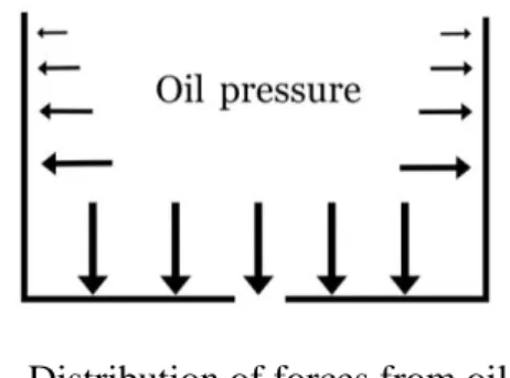
It is assumed that the oil leakage is caused by an increase of pressure inside the oil tank. This pressure forces the oil through the opening of the cylinder and past the piston, so a relieving of that pressure would prevent the leak to start. By expanding the area of the tube around the opening, the pressure of the oil is distributed over a larger surface and therefore decreased at the opening to the piston. This principle is illustrated in figure 6.
Figure 6 – Distribution of forces from oil pressure.
The rubber hose was carefully split in half using a scalpel. A cavity was cut out above the opening of the cylinder using the same tool. The hole expanded the tube from its original 2.5 mm in diameter to approximately 6 mm in diameter. The oil hose was then glued back together, and oil-pump system filled with oil and left to see if leakage occurs. Leakage occurred due to the glued oil-hose.
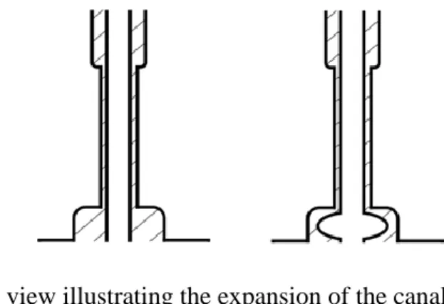
As this did not work, a second set of tests was made, this time using a Dremel tool to make a smoother cavity and reach further in the opening of the rubber hose. By using a Dremel tool, the canal was expanded without cutting open the hose. The results of this test were the same as the previous.
Results and implementation
Figure 7 – Section view illustrating the expansion of the canal inside the oil-hose.
From left to right.
The oil systems still leaked oil after the cavity was made, but most of the oil leaked out through the fitting between the rubber hose and the cylinder. The glue made it harder to close the system entirely due to its stiffness. When sealing off the cylinder with extra glue to prevent oil pushing through the fitting, an oil leakage occurred through the intended opening in the system. The oil still pushed through the system.
Because the tools used for making the rubber hose is costly, it is not possible at this time to make a wholly sealed prototype to test.
4.3.3.2
Breather valve
The only way for the system to release unintended pressure that builds up inside the oil tank is to push oil through the system and out through either the oil outlet or the fitting between the piston and the cylinder. Introducing into the system an alternative way for the pressure to equalize with the atmospheric pressure, the unintended flow of oil would be eliminated. A breather valve would effectively allow air to pass through the solid walls of the oil tank, assuring that the pressure inside is in constant equilibrium with the atmospheric pressure.
A functioning breather valve requires a specific design that allow air to pass through but constrain the oil from passing through the valve. In the initial stages of the testing phase, this was not possible to test on a prototype. But to represent a working breather valve a hole was drilled in the tank wall, allowing air to pass through. The test was then hung up to investigate if leakage would occur.
Results and implementation
With the hole in the wall, the pressure does not increase within the oil tank. With the constant contact with the atmospheric pressure, the only force working on the piston in the system is the gravitational pressure from the oil pushing on the system. This pressure by itself is not enough to force the oil through the system.
From the result of this test, the concept of a breather valve would translate in the same way. The breather valve would allow the air to pass through the tank wall continuously while at the same time preventing the oil from passing through the valve. The resources to investigate further was not at disposal, but this is recommended for further research in section 6.4 –
Further work and research.
4.3.3.3
Marking a fill-level on the tank
The oil leakage occurs as the pressure builds in the tank, forcing the oil to flow through the system. When filling the tank to the brim, a leakage occurs almost instantly when closing the tank cap. By not filling the tank all the way up, there is room left for air to fill the remainder of the tank. Air as gas is compressible, compared to a fluid like oil, and therefore takes up less space [3, p. 42] [4, pp. 46-47] [6, p. 11]. When the pressure increases, the air is compressible enough to avoid the oil pressing through the oil hose.
The oil in the tank was carefully measured and filled half way, leaving the rest of the tank filled with air. The tank was then fitted on the construction and tested for leakage. This was done with two separate test subjects.
Figure 9 – Example of suggested oil level.
When returning to the test two hours later, both subjects had leaked oil.
As both tests had resulted in an oil leakage, it is apparent that the amount of oil inside the tank does not affect the leakage. The only difference from a test with a tank filled to the brim is the time it takes to start leaking. A full tank starts to leak almost instantly, and the half-filled tank had a delay of approximately half an hour.
4.3.3.4
Obstruction in tank outlet
As the pressure builds up inside the tank, the oil is pushed through the system. By placing an obstruction where the oil exits the tank into the oil hose, the oil will not exit the tank unless the pump pulls it through the system. This obstruction will act as a valve, closing the system until a flow is created. The valve will be placed inside the oil plummet, and as this is solid brass it can be hollowed out and still fulfill its function.
Results and implementation
Figure 10 – Section view of oil plummet with and without obstruction.
The canal through the oil plummet was widened using a drill. With the new diameter a so-called 'duckbill valve' would fit inside. The oil plummet with the duckbill is then inserted into the system and left to evaluate leakage. There are two subjects used in this test. The first one is an entirely fresh system that has not been used before. In the second one, the system has been run and then turned off, so that oil is contained in the system.
Returning to the tests the next day a leakage had occurred in both subjects.
The leakage in this test was equivalent to tests without the obstruction inside the oil plummet. The obstruction increases the pressure needed to force the oil through the system, but not enough to prevent leakage.
4.3.3.5
Soft tank walls
A test was set up with soft tank walls to dispose of the excess pressure in the oil tank. One of the tank walls was cut out and exchanged for a thin membrane made of a plastic glove. As the pressure increases, the glove expands and prevent leakage through the system.
Figure 11 – Placement of soft tank wall.
A fresh system was put together with the re-constructed oil tank and full of oil. It was then left for more than an hour to see if the leakage would occur.
The results were the same as the system with hard tank walls. The pressure relief from the soft tank wall was not enough to compensate the pressure build up and therefore does not prevent a leak.
Results and implementation
4.3.3.6
Stop piston in right position
The leakage most often occurs when the piston is in a position that allows a flow through the system. If the piston were to stop in a position that does not allow that flow, no oil would leak through the outlet hose. There would still be leakage through the fitting between the cylinder and piston, but compared to the outlet leakage this would be considered a minor problem.
Figure 12 – Position of cavity in piston that doesn’t allow a flow.
To make the piston stop in the right position it is necessary to stop the motor in the right position, or somehow decouple the piston from the pump pinion. When talking to Husqvarna employees working with the products drive systems, it is made clear that it is not possible in the current situation to make the motor rotation stop at an exact point. When analyzing this further, it is also clear that it is not possible to leave the motor in the same exact position until next used. It is needed to move the chain when switching to a new, or when sharpening the chain edges. That only leaves decoupling the piston from the pump pinion. In the current system of components, this would mean a significant change in components and design. Since one of the objectives is to leave as much as possible the same, this would not be recommended. If there are no other suitable options, this one can be revisited.
4.3.3.7
Clamp the hose
Another way to stop the leakage is to clamp the hose shut. One possibility is to use the centrifugal force of the rotating motor, but this would be both expensive and space consuming. Another way is to use electricity, to a so-called "hose pinch valve".
The rubber hose is pinched shut at the section after the cylinder and before the outlet using a pair of pliers. The pliers were taped in the closed position to maintain the pinch throughout the length of the test. The test subject was then hung up to see if leakage occurred.
When returning to the test subject the next day no leakage had occurred through the oil outlet, but oil had leaked out through the fitting between cylinder and piston.
Figure 13 – Marking of the clamp position.
Clamping the hose does not solve the problem with the leakage as there are other ways for the oil to escape the system. If the hose to the outlet is sealed off, the system will find another way
Results and implementation
4.3.3.8
Venting the lid
The tank lid was assessed to investigate the reason for the pressure build-up in the tank. The rubber sealing on the lid closes off the air flow before the lid is screwed on tightly. Measuring the levels of the lid when tightening it shows that it is lowered another 5 mm from sealing to screw on tight. The air inside the tank is compressed because of this, and does not have anywhere to release. Because of this, there is a pressure higher than the atmosphere inside the tank already when the tank lid is closed.
By drilling a hole in the tank lid, a flow channel for the air is created. When tightening the lid, the air inside the tank and outside the tank is therefore in constant equilibrium. After the lid is screwed on tight the hole is sealed off with glue and made sure to be completely sealed off. The test subject was then hung up for an hour to see if leakage occurred.
The test did not result in any leakage.
The venting of the lid relieves the system of the immediate pressure that builds up, because of the lid being screwed into place. Avoiding this initial increase, the pressure in the tank remains at an atmospheric level if conditions around the system remains the same. Further testing is required to determine the effectiveness as temperatures and air pressure change around the product.
An alternative design on the same concept was developed. Instead of drilling a hole in the lid, a canal was carved in the tank where the lid is screwed in place. This canal works as a reliever, ensuring that the lid does not seal the air in the tank until the last turn when closing it. The results of this design are identical to the previous.
Results and implementation
4.3.4
Summary of concepts
This section is a summary of the testing phase. The outcome refers to the results of the tests performed on the concept. The effectiveness accounts for how effectively the concept prevents a leakage compared to the original design.
Concept
Section Outcome
Effectiveness
Equalization of oil pressure
4.3.3.1
Leakage through outlet
No difference
Breather valve
4.3.3.2
No leakage
Effective
Marking a fill-level on the
tank
4.3.3.3
Delayed leakage through
outlet
No difference
Obstruction in tank outlet
4.3.3.4
Leakage through outlet
No difference
Soft tank walls
4.3.3.5
Leakage through outlet
No difference
Stop piston in right position
4.3.3.6
Inconclusive
Inconclusive
Clamp the hose
4.3.3.7
Leakage through fitting
No difference
Venting the lid
4.3.3.8
No leakage
Effective
Table 3 – Summary of tested concepts.
Following are comments from one of the senior engineers at Husqvarna. The successful concepts were presented to the engineer to give a professional opinion on these.
4.3.4.1
Comments from Husqvarna regarding concepts
As shown in Table 3, the two effective concepts are Breather Valve and Venting the Lid.
Presenting these two options to a senior test engineer at Husqvarna resulted in several remarks. The breather valve might not perform as planned since it requires a certain amount of pressure to work. The valve might also be difficult to place correctly. Since the pole saw can be stored in multiple ways, the tank is not always positioned the same and therefore inhibit the valve. The vented lid might be worth implementing right away since there has been trouble with leakage in stores when selling the product. A similar solution has been discussed at Husqvarna.
Results and implementation
4.3.5
Summary of results of generating design concepts
The concept testing phase included eight concepts that were tested and evaluated. From these, there were one short-term concept and one long-term concept that potentially will answer the second question of the thesis.
Described insection 4.3.3.8 – Venting the lid, is a short-term solution that eliminates an initial
and immediate increase of pressure inside the tank, when the tank is filled with new oil. By allowing the air to flow past the lid up to the last turn of the screw, no excess air is pushed into the tank to increase the pressure. The inside, therefore, remains in atmospheric pressure. This solves the problem if the conditions of the surroundings stay the same. If there are changes in pressure or temperature around the system, leakage will still occur.
To avoid leakage during changes in the climate around the system, the concept of a special valve was investigated. With this concept the valve will allow air to exit the oil tank if the pressure increase inside. If the temperature increases, the air inside the tank will expand. When this happens, the air needs a relief valve to pass through to avoid pushing the oil through the system. With constant contact with the atmosphere, the leakage will be eliminated as the pressure will never build up enough to push the oil through the cylinder.
Analysis
5
Analysis
This chapter is an analysis of the process and method of the thesis with its results. The results of each aim of the thesis are analyzed individually and tied back to the theoretical framework. Likewise, the chosen method for the thesis is analyzed and motivated. The validity and reliability of the results are reasoned around and accounted for at the end of the chapter.
5.1 Analysis of results of aim 1
The limited size of the system, and foremost the oil tank, increases the likelihood of build-up in pressure. The design of the oil pump is developed so the pressure is balanced when a vacuum is created. If oil is pumped through the system, the volume of oil that disappears from the tank is replaced with air that enters through the duckbill inlet at the top of the tank. When the opposite occurs and the volume of the oil or the air in the tank increases, there is no relief valve to let out the excess air.
Changes in temperature bring about this problem as the volume inside the tank decrease as the temperature of the system goes down. When this happens, the duckbill vent effectively allows air to enter the tank. As the temperature increase again, the new air will expand, and the pressure inside the tank will increase with the extra volume. The only way to relieve the pressure is for the oil to be forced through the system and out through either the outlet or the fitting of the cylinder, as described in section 2.3 - Theory 2.
5.2 Analysis of results of aim 2
A pressure relief system is critical to the success of the solution. The ventilation system incorporated in the tank lid provides a temporary solution that solves the initial problem when closing the tank. Initial leakage is caused by the increased pressure that comes from the compression of the air when screwing in the lid. Until the volume decreases inside the tank, this is a viable solution. The senior engineer consulted in section 4.3.4.1 Comments from
Husqvarna regarding concepts agrees with this assessment.
However, the problem remains when the pressure increases or the temperature increases in the tank. By installing the valve described in section 4.3.3.2 – Breather valve, the system is continuously in equilibrium with the atmospheric pressure. With the internal pressure of the tank eliminated the only force working to push the oil through the system is the gravitational pull acting on the oil as described in section 2.2 - Theory 1. The oil pump is designed to
withstand this force without allowing an unintentional flow of oil to pass through the cylinder. When presenting the results to a senior engineer at Husqvarna, concerns were raised regarding the performance of the breather valve. The breather valve might not perform as planned since it requires a certain amount of pressure to work. This required pressure risk to coincide with the pressure at which the pump allow oil to push through the system. The valve might also be difficult to place correctly since the pole saw can be stored in multiple ways and therefore the tank is not always positioned the same.
When comparing the two concepts with the function analysis from section 4.2 – Definition
results, all functions required are accounted for. The necessary function Prevent pressure
build-up though, is only partially fulfilled for the redesigned tank lid. As for the breather valve, the function most at risk of being compromised is the cost for the component since the valve is small but highly technical.
Neither of the concepts affects the current systems components or purposes, as shown in the system analysis found insection 4.2.2 – System analysis, except for the design of the oil tank.
Analysis
5.3 Analysis of method choice
The initial investigation, found in section 4.1 – Test for detection of leakage, laid a foundation for the continued research of the cause of the leakage. The testing in the primary phase of the work gave a general idea of the cause, location and extent of the leakage. The following steps of the process, generating and testing ideas were done parallel to each other, with a trial and error approach [8, p. 261]. Each trial yields additional information and learning [15, p. 128]. The set based concurrent engineering method as described in section 3.4 – Concept study, provides a useful structure to gain more knowledge and understanding about the problem as testing was performed. This led to new ideas generated and with each new test a deeper understanding was gained.
Using a more traditional method of solving the problem [10, p. 53], such as various point-based approaches, would perhaps lead to a viable solution, although it would require a more extensive research and understanding before the generating and testing phase could be started. The limiting factor with these point-based methods is that most require narrowing down to only one solution before proceeding to the next step. With the limited knowledge and understanding of the problem it was decided to proceed with the concurrent engineering method, mainly to open for many concepts that continuously increase the understanding of the problem. [8, p. 261] The experimental approach to development has been expensive in the past, in terms of time involved and labor expended. Given modern technologies it is now economically viable to perform more experiments in the development process, and with that accelerate innovation. [15, p. 125]
5.4 Validity and reliability
The validity and reliability of the tests performed in this thesis can be disputed. The method and structure of the testing phase is of an experimental nature with many concepts and many ideas investigated and tested at the same time. If a narrower approach were to be used, more detailed testing would be recommended. The tests performed in the thesis were often tested with one or two test subjects on a limiting testing period. It can be argued that these results have not been sufficiently tested and confirmed. But for the progression of the process it was decided to test the concepts with an experimental approach and analyzing the results to determine if additional testing is necessary. In most cases this was not necessary as the result could be motivated and confirmed with the theoretical framework.
When conducting experiments, it is important to measure not only data but the uncertainties in the measurements [6, pp. 15-16]. These uncertainties can affect the certainty in the final result [6, pp. 15-16]. Often, the more accurate the measurements, with smaller uncertainties, the more expensive it gets [6, pp. 15-16]. The tests conducted in this thesis has a high uncertainty in measurements.
Also, since the thesis has been carried out by people, the design is limited by their cognitive capabilities [11, p. 50]. By the incomplete data received at the first steps of the process, it is not certain that the most important functions have been identified, or even any viable concepts [11, pp. 56-57]. Every developer understands the problem differently and therefore solves the problem differently [11, p. 57]. Developing a design can be considered an investigative process [16, p. 119]. The additional information found during the developing process open for new solutions, but these new solutions creates in turn new and different problems [16, p. 118]
Discussion and conclusions
6
Discussion and conclusions
This chapter concludes the thesis, with final remarks and recommendations. The content in each section is documented for the thesis to have relevance for further work and research.
6.1 Conclusions
If the problem is addressed in a way that only counteracts the leakage at the outletand fitting of the cylinder, the system will leak oil in other places. The problem is not in one specific location or component in the system, but caused by a collection of reasons acting at the same time. Therefore, the solution must be directed at the root of the problem; the over-pressure. The conclusion is therefore that an alternative function or component must be added to the system to address this.
6.1.1
Answer to question 1 of the thesis
One cause of the leakage is an unintended increase of pressure within the oil tank. The piston is designed to close off the flow of oil when static, however, the increased pressure forces the oil around the piston when it should be sealed.
6.1.2
Answer to question 2 of the thesis
By relieving the pressure within the oil tank there is no additional pressure created. Introducing an element into the system preventing this increase of pressure would resolve a majority of the unintended oil leakage. The suggested solutions in section 4.3.3.2 – Breather valve and section
4.3.3.8 – Venting the lid can be the sought element.
6.2 Reflections
The most limiting factor throughout the thesis was maintaining the timeframe, and several ideas were put on hold because of this. The complexity of the problem increased as the research progressed. This provided new complications and the investigative process generated new hurdles.
The progression of the thesis led up to a conclusion that projects a loop pointing to the beginning of the thesis. The cause of the problem is in the design of the system that both allow an increase of pressure and fail to prevent an unintended flow of oil. To reach a solution, the information around the cause of the leakage would have been necessary at the beginning of the thesis.
The choice of method used in the thesis is therefore not disputed, as the concurrent engineering method is a useful tool. This method increases knowledge of the problem while generating a solution. But with many other methods to use for the development process the choice is not obvious in hindsight, with the new knowledge gained.
Seen from a wider perspective, this issue can have greater consequences then seen initially, since the company takes full environmental responsibility. Although the leak has gone through the quality approval, and must therefore not be considered a big threat from the company’s side, it can still have consequences for the brand in the future.
6.3 Recommendations
Since this thesis did not reach one definitive, verifiable solution to the leakage, the company will need to continue this work. Although, the work done in this report might act as a guide towards solving the problem. Several of the tested concepts have been discarded as non-viable, giving a direction for further research.
The recommendation is to continue with the breather valve concept described in section 4.3.3.2
– Breather valve, to see if it works as intended and if the cost is feasible. If the company is
looking for a quick and cheap solution they can move forward with the venting of the lid, since this partially solves the problem. The vented lid might be implemented until a viable solution is finished.
Discussion and conclusions
The complication that comes with a viable solution that solves every aspect of the problem, is ultimately the cost of the solution concept. Because of the tests performed, a conclusion can be drawn that the solution will increase the production cost of the oil pump system. There are also several major changes to be made in the current design, if a working solution will be at all possible.
The final conclusion is that this issue must be solved, even if it is costly, as this can yield far-reaching negative effects for the company’s credibility in a broader perspective.
6.4 Further work and research
The thesis provides a detailed problem description and cause of the leakage. The location of the leakage does not need further investigation. The focus needs to be directed to why there is a problem with this particular design of the oil pump. Why does the design allow a flow of oil when the pressure is increased? Connected to this question is competing brands products, as not all have the same problem with oil leakage.
A continued research is necessary in finding solutions for relieving the pressure built up inside the tank. There are two solutions provided in the thesis that require further testing and development. Foremost the concept with the breather valve need to be tested to see if it provides an effective solution. The venting of the lid concept should also be investigated further to determine if it can be implemented as a fully working solution in production.
Further, it is recommended to continue generating concepts and ideas not mentioned or tested, using the results of the thesis as a foundation. In addition, it is recommended to do an impact assessment combined with an economic calculation to prevent significant increases in production cost.
In the economic calculation, it is important to consider the problem from a broader perspective. The company should appoint a multidisciplinary project team to weigh different consequences, such as the brand against the economic aspect.
References
7
References
[1] Husqvarna Group AB, ”husqvarna.com,” Husqvarna Group AB, [Online].
Available: www.husqvarna.com/se/produkter/motorsågar. [Used 30 04 2018].
[2] Husqvarna Group AB, ”husqvarnagroup.com,” Husqvarna Group AB , [Online].
Available: www.husqvarnagroup.com/sv/ansvarsfullt-foretagande/
milj%C3%B6ansvar. [Used 30 04 2018].
[3] A. J. Smits, A physical introduction to fluid mechanics, Princeton: A.J. Smits,
2018.
[4] Y. Nakayama, Introduction to fluid mechanics, Tokyo: Yokendo Co. LTD, 1999.
[5] F. M. White, Fluid Mechanics - Seventh Edition, New York: McGraw-Hill, 2011.
[6] J. P. Pritchard, Fox and McDonald's Introduction to fluid Mechanics, Hoboken:
Jon Wiley & Sons, Inc, 2011.
[7] B. Massey och J. Ward-Smith, Mechanics of Fluids, Seventh Edition, Volume 1,
Cheltenham: Stanley Thornes Ldt, 1996.
[8] H. Johannesson, Produktutveckling: effektiva metoder för konstruktion och
design, Stockholm: Liber AB, 2004.
[9] W. E. Eder, Introduction to design engineering: systematic creativity and
management, London: Taylor & Francis Group, 2010.
[10] G. Pahl, W. Beitz, J. Feldhusen och K.-H. Grote, Engineering Design: A
systematic approach Third Edition, London: Springer, 2007.
[11] G. D. Ullman, The Mechanical Design Process, Forth edition, New York:
McGraw-Hill, 2010.
[12] P. Rodgers och A. Milton, Product Design, London: Lawrence King Publishing
Ltd, 2011.
[13] K. Österlin, Design i fokus för produktutveckling: varför ser saker ut som de gör?,
Malmö: The author and Liber AB, 2010.
[14] N. Cross, Engineering design methods: strategies for product design, Chichester:
John Wiley & Sons Ltd, 2008.
[15] O. Gassmann, Management of the Fussy Front End of Innovation, Cham:
Springer International Publishing, 2014.
References
[16] B. Lawson, How designers think: the design process demystified, Burlington:
Bryan Lawson, 2006.
[17] Nationalencyklopedin,
”NE,”
[Online].
Available:
http://www.ne.se/uppslagsverk/encyklopedi/lång/hävert [Used 12 04 2018].
[18] R. Patel och B. Davidson, Forskningsmetodikens grunder - Att planera,
genomföra och rapportera en undersökning, Lund: The authors and
Studentlitteratur, 2011.
Appendices
8
Appendices
8.1 GANTT schedule
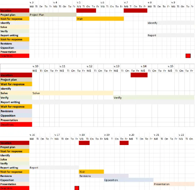
The GANTT schedule attached in this appendix is the basis of the time distribution throughout the thesis. Included is the various steps towards the final hand in and presentation of the thesis with individual deadlines.
Appendices
8.2 To do list
The list attached in this section is the to do list. The list provided a strucuture to the work and clear steps of progression. Every step was marked when started and finished for a overview of the progression in addition to the GANTT schedule in section 8.1 - GANTT schedule.