V¨
aster˚
as, Sweden
Thesis for the Degree of Master of Science in Computer Science
-Embedded Systems 15.0 credits
PERFORMANCE ANALYSIS OF THE
PREEMPTION MECHANISM IN TSN
Lejla Murselovi´c
lmc19002@student.mdh.se
Examiner: Saad Mubeen
M¨
alardalen University, V¨
aster˚
as, Sweden
Supervisors: Mohammad Ashjaei
M¨
alardalen University, V¨
aster˚
as, Sweden
Abstract
Ethernet-based real-time network communication technologies are nowadays a promising communi-cation technology for industrial applicommuni-cations. It offers high bandwidth, scalability and performance compared to the existing real-time networks. Time-Sensitive Networking is an enhancement for the existing Ethernet standards thus offers compatibility, cost efficiency and simplified infrastructure, like previous prioritization and bridging standards. Time-Sensitive Networking is suitable for networks with both time-critical and non-time-critical traffic. The timing requirements of time-critical traffic are undisturbed by the less-critical traffic due to TSN features like the Time-Aware Scheduler. It is a time-triggered scheduling mechanism that guarantees the fulfilment of temporal requirements of highly time-critical traffic. Features like the Credit-Based Shapers and preemption result in a more efficiently utilized network. This thesis focuses on the effects that the preemption mechanism has on network performance. Simulation-based performance analysis of a singe-node and singe-egress port model for different configuration patterns is conducted. The simulation tool used is a custom developed simulator called TSNS. The configuration patterns include having multiple express traffic classes. In a single-egress port model, the most significant performance contributor is the response time and this is one of the simulation measurements obtained from the TSNS network simulator. The comparison between the results of these different network configurations, using realistic traf-fic patterns, provides a quantitative evaluation of the network performance when the network is configured in various ways, including multiple preemption scenarios.
Table of Contents
1. Introduction 1 1.1. Motivation . . . 1 1.2. Problem Formulation . . . 2 1.3. Thesis outline . . . 2 2. Background 3 2.1. Computer Network . . . 3 2.2. Ethernet . . . 32.2.1. Shared (broadcast) Ethernet . . . 4
2.2.2. Switched Ethernet . . . 4
2.2.3. Industrial Ethernet . . . 5
2.3. Time-Sensitive Networks . . . 6
2.3.1. IEEE 802.1AS - Timing and Synchronization for Time-Sensitive Applications 6 2.3.2. IEEE 802.1Q - VLAN Priority Queuing . . . 7
2.3.3. IEEE 802.1Qav - Forwarding and Queuing Enhancements for Time-Sensitive Streams . . . 10
2.3.4. IEEE 802.1Qbv - Enhancements for Scheduled Traffic . . . 12
2.3.5. IEEE 802.3br and 802.1Qbu Interspersing Express Traffic (IET) and Frame Preemption . . . 14
3. Related Work 18 3.1. Performance evaluation of real-time Ethernet Standards . . . 18
3.2. Performance analysis of individual TSN standards . . . 18
3.3. Evaluation of TSN with Frame Preemption . . . 18
3.4. Existing network simulators . . . 19
3.5. Discussion . . . 20
4. Method 20 5. Ethical and Societal Considerations 22 6. Effects of the Preemption Mechanism 23 6.1. Schedulability . . . 23
6.2. Guard band size . . . 23
6.3. Preemptable configuration of scheduled traffic . . . 24
6.4. Multiple scheduled traffic classes . . . 25
6.5. Effects on the SR traffic class . . . 25
6.6. Preemption effects in a multi-SR traffic class configuration . . . 26
6.7. Multiple ST and SR traffic classes . . . 28
6.8. Lower priorities as express . . . 29
7. Time-Sensitive Network Simulator TSNS 31 7.1. Assumptions . . . 31
7.2. TSNS egress port model design . . . 31
7.2.1. Queuing . . . 33
7.2.2. Transmission Selection Algorithm . . . 34
7.2.3. Gate mechanism . . . 34
7.2.4. Transmission Selection . . . 35
7.2.5. Preemption mechanism . . . 35
8. Evaluation 39 8.1. Scenario 1: Single-simulation - Offline generated message set - Per-message results 40
8.1.1. Results . . . 41
8.1.2. Discussion . . . 42
8.1.3. Conclusion - Scenario 1 . . . 42
8.2. Scenario 2 - Express ST and multiple express SR traffic . . . 42
8.2.1. Results . . . 43
8.2.2. Conclusion - Scenario 2 . . . 44
8.3. Scenario 3 - No ST traffic class . . . 45
8.3.1. Results . . . 46
8.3.2. Discussion . . . 47
8.3.3. Conclusion - Scenario 3 . . . 47
8.4. Scenario 4 Express ST and various single express SR express ST and express LP -High number of traffic classes . . . 48
8.4.1. Results . . . 48 8.4.2. Discussion . . . 49 8.4.3. Conclusion - Scenario 4 . . . 50 9. Conclusions 51 9.1. Future work . . . 51 10.Acknowledgments 52 References 55
List of Figures
1 The evolution of Ethernet in the 20th century . . . 3
2 Master-slave architecture for time synchronisation in IEEE Std 802.1AS [1] . . . . 7
3 Insertion of IEEE 802.1Q Tag in the Ethernet frame . . . 7
4 Software Architecture of the Bridge with Strict Priority Selection . . . 9
5 Credit-Based Shaper Algorithm operations in different conditions . . . 11
6 Software Architecture of the Bridge with the Credit-Based Shaper Algorithm . . . 11
7 Time-triggered scheduled traffic transmission . . . 12
8 Operation examples of the CBS with TAS . . . 13
9 Software Architecture of the Bridge with Time-Aware Scheduler . . . 14
10 Preemptable MAC (pMAC) and express MAC (eMAC) scheme [2] . . . 15
11 Preemption Mechanism Trace Example . . . 16
12 Hold and Release mechanism enabled vs. disabled . . . 17
13 Research framework [3] . . . 20
14 Preemption configuration causing ST traffic latency . . . 24
15 Credit behaviour of express Class A . . . 26
16 Example trace with no express frames . . . 27
17 Example trace with only Class A - express . . . 27
18 Example trace with only Class B - express . . . 28
19 Example trace with both Class A and B - express . . . 28
20 Response time of LP traffic in express vs. preemptable configuration . . . 30
21 TSNS Switch model . . . 32
22 Defined TSNS structures . . . 33
23 Overall software architecture design of the simulator . . . 33
24 Credit flow diagram . . . 34
25 TS flow diagram . . . 36
26 Preemption flow diagram . . . 37
27 TSNS model design . . . 37
28 Scenario 3- Bar-graph representation of response time per-class . . . 47
29 Scenario 4 - Plot of results - Average response time per traffic class . . . 49
1.
Introduction
In traditional communication networks there in no common time-base concept and as a result, these networks can not provide synchronization nor precision timing. Reliable delivery of data is more important than the time window in which these are delivered so there is no need for timing constraints. Soft requirements can not be used in real-time embedded systems that are specified by strong constraints concerning timing. A set of standards is developed defining mechanisms that consider time constraints, for data transmission over deterministic Ethernet networks, called Time-Sensitive Networking (TSN) [4].
TSN is an extension of conventional switched Ethernet network protocols with several additional fea-tures, such as hard real-time guarantee on time-critical traffic and preemption support. The primary standard is IEEE 802.1Q-20181and there are several amendments on enhancing various mechanisms,
such as IEEE 802.1Qav2, IEEE 802.1Qbu3 and IEEE 802.1Qbv4. The key components of a TSN
network that enable real-time capability in Ethernet-based machine-to-machine communication are time synchronization, scheduling and traffic shaping and selection of communication paths, path reservations, and fault-tolerance [4]. One of the interesting features in the standards is preemption support for Ethernet frames where an time-critical frame can preempt a low priority Ethernet frame.
A deterministic Ethernet network is a time predictable network. Timing predictability of a system is the term describing that all specified timing requirements are being satisfied once the system starts executing [5]. It is necessary to be able to show or prove this guarantee, using some mathematical analysis, for the system to be called time predictable.
Because of its high bandwidth, compatibility and scalability, Ethernet-based communication is rapidly advancing as it is being widely considered in different markets. For some markets, like the industrial market, the biggest drawback of these networks is their lack of timing predictability in data delivery. The continuously increasing amount of data that is being transmitted in distributed embedded systems, makes satisfying the timing requirements harder. This is the main reason for introducing TSN.
TSN offers time predictability together with high-bandwidth that goes up to 10 Gbps in or-der to implement the throughput necessary for future applications associated with automation, digitalization and Industry 4.0 where high-bandwidth is extremely important considering the large amount of data that is being transmitted and considering the temporal importance of data delivery in networks that transmit safety-critical and control data. The other benefit of TSN is the fact that IEEE is standardizing TSN in such a way that a variety of applications can use it.
1.1.
Motivation
To evaluate the feasibility of an Ethernet-based communication network for future industry applica-tions, it is important to identify specific and comparable network metrics. Moreover, a detailed quantitative analysis allows for optimizations, and can be used to propose and rate improvements of the network protocols.
As a relatively new standard added to the TSN family of standards, the preemption mecha-nism is not well researched in the context of TSN. The existing research focuses on the default preemption configuration with one express traffic class. This thesis aims to broaden the domain for the preemption mechanism and provide insight into the effect multiple express traffic classes have on the network performance. The effects of having express traffic classes in unconventional configurations is unknown and understanding it can lead to a faster uprising of TSN and better optimisation of Ethernet-based networks. This thesis engages with these corner questions and
1IEEE 802.1Q: Available from [Online]: https://ieeexplore-ieee-org.ep.bib.mdh.se/document/8403927 2IEEE 802.1Qav:Available from [Online]: https://ieeexplore-ieee-org.ep.bib.mdh.se/document/8684664 3IEEE 802.1Qbu:Available from [Online]: https://ieeexplore-ieee-org.ep.bib.mdh.se/document/7553415 4IEEE 802.1Qbv: Available from [Online]: https://ieeexplore-ieee-org.ep.bib.mdh.se/document/8613095
establishes new hypotheses that contribute to the body of knowledge on the preemption mechanism in TSN.
A simulation-based analysis is suitable and provides the necessary performance estimates. Automo-tive applications have very strict requirements, usually the temporal precision must be within a few microseconds, so it is necessary to simulate the temporal behaviour with high accuracy.
1.2.
Problem Formulation
The IEEE 802.1Qbu standard defines two modes for a traffic class, which are express and preempt-able. Express frames can interrupt transmission of preemptable frames. Each port of a TSN switch can support up to 8 queues, i.e., support up to 8 traffic classes. We focus on the following three traffic class types that are defined in the IEEE 802.1Q standard: Scheduled Traffic (ST), which high priority traffic class that is transmitted according to a time schedule that is created offline, to ensure no interference from other traffic classes. The traffic is strictly periodic and represents the network control signals. The second type is Stream Reserved (SR) traffic classes with reserved bandwidth, based on the Stream Reservation Protocol (SRP). This traffic undergoes traffic shaping based on credit. In practice the highest-priority SR traffic class is referred to as Class A, then comes lower-priority Class B, then Class C and so on. Lastly, we define Best-Effort (BE) traffic class, which is low-priority traffic, that is handled without temporal and delivery guarantees. BE traffic can be sporadic, aperiodic or periodic and it does not undergo traffic shaping.
For each traffic class, one can configure it to be real-time traffic undergoing a credit-based shaper (SR), scheduled traffic (ST) which is not going through the credit-based shaper, and best-effort traffic class. The TSN standards allow defining a gate mechanism for all traffic classes to control the traffic transmission by preventing any traffic class in favour of ST class. On top of these mechanisms, each queue can be defined as express (that can preempt preemptable lower-priority classes) or as preemptable (that cannot preempt any other classes but can be preempted itself).
As observed, the configuration can be very complex, given many configuration parameters. The objective of this thesis is to investigate what are the effects of configuring multiple traffic classes as express on the performance of all traffic classes, more in-depth understanding of TSN standard and awareness of edge cases and corner cases. This thesis aims at providing an answer to the following research question:
RQ: How is the performance of the time-sensitive network affected by various configurations of traffic classes as express or preemptable?
To answer this question, we investigate various cases with different traffic class configuration patterns, with an emphasis on the preemption configuration where multiple classes are set as express. The cases are evaluated using a simulation tool.
1.3.
Thesis outline
In Section 2., we give background on the main concepts and terms this thesis is built on. The main outlines are the background on computer networks, Ethernet and lastly TSN, where some highlighted mechanisms are described. In Section 3., we discuss related work on this topic. We then discuss how we deal with the formulated problem, tools and method used to answer the research question, in Section 4. In Section 6. we propose assumptions and possible answers based on the body of knowledge. To verify the accuracy of this approach and evaluate the assumptions, we develop a network simulator described in Section 7. Finally, in Section 8., we present and discuss the results of use-cases and scenarios that address the research questions, and have been run in the simulator. Section 9. summarizes and concludes this thesis.
2.
Background
2.1.
Computer Network
A computer network is a digital telecommunication network that enables digital information sharing between terminal nodes that in the case of computer networks are computing devices. These devices can execute arithmetical or logical operations from a given instruction or a set of instructions. Computer devices, like routers and switches, are connected either with a physical cable, for example, fiber-optic cables, to enable data transmission or using some wireless method where transmission is supported by electromagnetic waves, for example, Wi-Fi. Computer networks may be classified by many criteria, for example, the transmission medium used to carry their signals, bandwidth, the network’s size, topology, communications protocols to organize network traffic and traffic control mechanism.
A communication protocol is a set of rules that allow two or more entities of a communications system to transmit data. The protocol defines the rules, syntax, semantics and synchronization of communication and possible error recovery methods. Internet communication protocols are published by the Internet Engineering Task Force (IETF). The IEEE handles wired and wireless networking, and the International Organization for Standardization (ISO) handles other types. The ITU-T handles telecommunication protocols, and formats for the public switched telephone network (PSTN). For the sake of understanding the terminology, the difference between the terms standard and protocol is stated. A protocol define a set of rules used by two or more parties to interact between themselves. A standard is a formalized protocol accepted by most of the parties that implement it. Not all protocols are standards; some are proprietary. Not all standards are protocols; some govern other layers than communication. An example of a standard outside networking is the standardization of paper sizes. Paper sizes were given abstract names, for example, ”A4”, is a protocol and this protocol was standardized by ISO organization. In networking, IEEE standardized the wired communication protocol Ethernet (IEEE 802.3) and wireless communication protocol Wi-Fi (IEEE 802.11). Annex A gives more details on the categorization and enhancement of standards.
2.2.
Ethernet
When the IEEE Std 802.3 Ethernet standard was first published in 1985 it described half-duplex communication system using the carrier sense multiple access with collision detection (CSMA/CD) method for collision handling. This specified how the hardware interacts with the transmission medium that is controlled by the medium access control (MAC) layer. Besides describing the MAC layer, the standard also described the medium attachment unit (MAU) that is responsible for the Ethernet physical medium. The original IEEE Std 802.3 Ethernet standard described the operations on a coaxial cable medium, supporting a bus topology [6].
Figure 1: The evolution of Ethernet in the 20th century
IEEE 802.3 is a working group and a collection of Institute of Electrical and Electronics Engineers (IEEE) standards that define the physical layer and media access control (MAC) of wired Ethernet.
CSMA/CD stands for Carrier Sense Multiple Access with Collision Detection. It refers to a set of rules determining how network devices respond when two devices attempt to use a data channel simultaneously, called a collision. Ethernet was introduces using the CSMA/CD protocol, but today it is considered obsolete, as the bus topology today is replaced with the star topology over twisted-pair medium and as hubs are replaced with switches.
2.2.1. Shared (broadcast) Ethernet
The Shared Ethernet is a network over a star topology using an infrastructure node or a central device called the hub. The hub is a simple broadcasting device that has a shared bus to which all the devices are connected. It could be seen as a ”bus in a box”. All the devices, except the sender device, would receive the sent data, and all members of the hub would have to wait until the bus is idle before sending data. The star topology made connecting and disconnecting devices in the network easy, as opposed to the true bus topology, where disconnecting one device meant taking down the entire network. Also, in 1984, the star topology of local area networks showed the potential of simple unshielded twisted pair cables. Twisted pair supports full-duplex communication, oppose its predecessor, the coaxial cable used for bus network topology. To understand this advantage, first, the terms full-duplex and half-duplex are explained. A duplex communication system is a point-to-point system composed of two or more connected parties or devices that can communicate with one another in both directions, oppose to a simplex. The two types of duplex communication systems are full-duplex (FDX) and half-duplex (HDX).
• In a full-duplex system, both parties can communicate with each other simultaneously. An example of a full-duplex device is a telephone; the parties at both ends of a call can speak and be heard by the other party simultaneously.
• In a half-duplex system, both parties can communicate with each other, but not simultaneously; the communication is one direction at a time. An example of a half-duplex device is a walkie-talkie.
The hub as a multiport repeater works by repeating transmissions received from one of its ports to all other ports. It can also detect a non-idle and idle line, as well as sensing a collision. A hub cannot further analyze or manage any of the traffic that comes through it [7]. A hub has no memory to store data and can handle only one transmission at a time. Therefore, hubs can only run in half-duplex mode. Due to a larger collision domain, there was a need for using more sophisticated devices as infrastructure nodes.
2.2.2. Switched Ethernet
The first Ethernet switch was introduced by Kalpana in 1990 [8]. The switch is a more sophisticated device in comparison with a hub. It is also an infrastructure node in a star network topology, but the switch can analyze and store the transmissions, hence it can support full-duplex communication. The switch does not broadcast the transmission to all the ports. Instead, it forwards the transmission only to the destination device. It has dedicated data ports for each end device. In the modern Ethernet, the devices of the network usually do not share the same bus or a simple repeater hub, but instead, use a switch. In this topology, collisions are only possible if station and switch attempt to communicate with each other at the same time and collisions are limited to this link. This means that the possibility of collisions is reduced to two devices, the switch, and the end device. Furthermore, the 10BASE-T standard introduced a full-duplex mode of operation which became common with Fast Ethernet and the standard with Gigabit Ethernet. The links in this standard are the twisted pair who support separated, dedicated, one-way channels cables for transmitting and receiving signals, so they don’t share the collision domain. Therefore modern Ethernets are completely collision-free. Modern Ethernet does not need CSMA/CD. CSMA/CD is still supported for backward compatibility and half-duplex connections. The IEEE 802.3 standard, which defines all Ethernet variants, for historical reasons still bore the title ”Carrier sense multiple access with collision detection (CSMA/CD) access method and physical layer specifications” until 802.3-2008, which uses the new name ”IEEE Standard for Ethernet”.
Link
Node
Hub Switch
Coaxial shared collision domain link collision domain Twisted shared collision domain individual collision domain
Table 1: The collision domain for different types of nodes and links
Today, the term Ethernet refers to a whole family of closely related protocols characterized by their raw data rates (10 Mbps, 100 Mbps, 1 Gbps or 10 Gbps) and the physical medium on which they operate. Ethernet now runs on a wide variety of physical media. Among the most common are: coaxial cable (thick or thin), many types of copper cable called twisted pair, and several types of fiber-optic cables using a variety of signaling methods and light wavelengths. It has outlasted Token Ring, ATM, FDDI, and other competing LAN technologies. It has extended from the LAN into the wide-area and wireless realms. Through technologies like switching and QoS controls, Ethernet has become the foundation technology for most networking communications today.
2.2.3. Industrial Ethernet
Opposed to the office networks systems for which the standard Ethernet is sufficient, the industrial or real-time networks demand more requirements to them, including determinism in reply time, critical requirements of real-time, equipment’s trustworthiness and resistance in hostile environments [9]. Time behavior in Industrial Ethernet is an essential aspect as it is responsible for communication in real-time procedures where priority and determinism are imperative characteristics. In the last three decades, different communication networks for the industrial environment have been developed so that the real-time factor is satisfied. These networks are called fieldbuses and some examples of these networks are: Profibus5, WorldFIP6, Foundation Fieldbus7, Controller Area Network (CAN)8
and DeviceNet9.
At the beginning of the 21st century, the Ethernet, despite being an interesting technology for industrial automation due to its high performance, low cost, and its expressive intolerability, did not support the requirements for industrial application [10]. Around 2005 research was done on Ethernet as an alternative communication system in the real-time industrial automation field. The Ethernet was just studied as an alternative as it had a critical downside compared to other industrial communication networks, which was its non-determinism. This problem was directly related to the non-deterministic control mechanism of the Carrier Sense Multiple Access Collision Detect (CSMA-CD) protocol [11].
Today Ethernet is a leading communication technology for industrial applications. As today’s Eth-ernet is collision-free, there is no need for using non-deterministic control mechanisms. Compared with other existing industrial networks, if offers high bandwidth and a significant reduction of cabling cost. The base standard of Time-Sensitive Networking IEEE 802.1Q introduced real-time support for Ethernet. It offers other benefits as well, such as bounded latency and zero jitter of time-constrained traffic classes and capability to handle multiple traffic classes on the same channel allowing its dominance as a communication system in the automation industry [12].
5Profibus: Available from [Online]: https://profibus.com.ar/ 6WorldFIP: Available from [Online]:
http://people.cs.pitt.edu/~mhanna/Master/ch2.pdf
7Fieldbus: Available from [Online]: http://www.fieldbus.org/
8CAN: Available from [Online]: https://ieeexplore.ieee.org/stamp/stamp.jsp?arnumber=788104 9DeviceNet: Available from [Online]: https://en.wikipedia.org/wiki/DeviceNet
2.3.
Time-Sensitive Networks
In need of time-synchronized low-latency transmission of time-critical data for real-time systems, the IEEE 802.1 Working Task Group started research on standards that were first meant for Audio-Video Bridging (AVB)10. Later on, this working group evolved into the Time-Sensitive Working Group. Simply said, time-sensitive networking (TSN) is the IEEE 802.1 defined standard technology that provides deterministic communication on the standard Ethernet. Deterministic communication is important to many industries, for example, aerospace, automotive, manufacturing, transportation, and utilities. TSN resides at layer 2 of the OSI 8 layer model, the ”Data Link Layer” of the standard Ethernet, defined by IEEE Std 802.3. Time-Sensitive Networking (TSN) means deterministic Ethernet is becoming standardized. Today it counts 11 IEEE Standards grouped under the IEEE 802.1 Working Group. TSN defines a large variety of scheduler and shaper solutions. Time Synchronization provides a mechanism for all network elements to have a common time base. Queuing and Shaping provides a mechanism for network elements to schedule and prioritize traffic. Highlighted technologies of TSN:
• 802.1AS Timing and Synchronization – Distributed clock
– Precision Time Protocol (gPTP) • 802.1Q VLAN priority queuing
– 8 queues based on VLAN priority tag
– Improves reliability but latency and buffering variations still occur on multi-hop networks • 802.1Qav Credit-Based Shaper
– Removes bursts in traffic to generate a constant bit rate – Avoids frame loss
• 802.1Qbv Time-Aware Scheduler
– Improves upon VLAN priority queuing by applying time slots
– With proper configuration can bound jitter and latency in the network • 802.1Qbu and 802.3br Frame Preemption and Interspersing Express Traffic
– Preemptable traffic and express traffic
2.3.1. IEEE 802.1AS - Timing and Synchronization for Time-Sensitive Applications Synchronising time in TSN is done by distributing time from a centralised time source through-out the network using the master-slave model. The synchronisation is based on the IEEE 1588 Precision Time Protocol, which utilizes Ethernet frames to distribute all information required for time synchronization. IEEE 802.1AS is a subset of the IEEE 1588 that narrows its protocols and mechanisms down to the necessary ones that apply to home networks or industrial automation and automotive industry networks. It also extends the IEEE 1588 to support time synchronisation over WiFi (IEEE 802.11) besides Ethernet (IEEE 802.3) and enables microsecond precision for environments that have tight timing requirements, as industrial applications have.
Figure 2 illustrates a general Precision Time Protocol (gPTP) that is responsible for the timing information distribution from the Grand master to all the end points. Every local clock has to be synchronised with the Grand Master Clock. The synchronisation branches from the Grand Master and its clock master port to the downstream clock slave ports in the bridges. Each bridge corrects the delay and propagates the timing information on all downstream ports, eventually reaching the
Figure 2: Master-slave architecture for time synchronisation in IEEE Std 802.1AS [1]
802.1AS end points. In the process of synchronisation, every bridge does its synchronization by calculating the link latency and frame residence time.
The frame residence time is the time required for queuing, processing and transmission from master to slave ports within each bridge. The link latency is the propagation delay between two adjacent bridges. The time synchronization accuracy depends mainly on the accuracy of the residence time and link delay measurements. 802.1AS uses a ratio between the local clock and Grand Master Clock oscillator frequencies to calculate synchronized time, and a ratio between local and Clock Master oscillator frequencies to calculate propagation delay.
2.3.2. IEEE 802.1Q - VLAN Priority Queuing
According to IEEE 802.1Q, standard bridging uses a strict priority transmission selection algorithm between eight distinct traffic classes, each with different priority level. Arbitration between frames of the same traffic class is usually done in FIFO order. These priority levels are defined by the value of the Priority Code Point (PCP) field in the 802.1Q Tag of a standard Ethernet frame, that was inserted to the original Ethernet frame, as shown in Figure 3.
Figure 3: Insertion of IEEE 802.1Q Tag in the Ethernet frame
The IEEE 802.1Q standard introduced the 802.1Q Tag or 802.1Q Header, which is a 4-byte field inserted between the Source MAC address and Ethernet type/length field of the original Ethernet frame. The 802.1Q Header consists of four fields:
1. TPID (Tag Protocol Identifier)
value of 0x8100.
2. PCP (Priority code point)
This 3-bit field describes the frame priority level. Value can range from 0 to 7, hence 8 different priority levels can be defined.
3. CFI (Canonical Format Indicator)
If this 1-bit field has the value of 1, the MAC address is in non-canonical format. If the value is 0, the MAC address is in canonical format.
4. VID (VLAN Identifier)
This 12-bit field identifies the VLAN to which the frame belongs. Value can range from 0 to 4095.
The eight priority levels provided by the 3 PCP bits allows groupings of different traffic types. The following eight traffic types recommended by IEEE [13] that can benefit from simple segregation from each other are shown in Table 21:
Traffic type Acronym Description
Background BK activities that should not impact the use of the network Best Effort BE for default use by unprioritized applications Excellent Effort EE important best-effort type
Critical Applications CA has a guaranteed minimum bandwidth Video VI less than 100 ms delay
Voice VO less than 10 ms delay
Internetwork Control IC in large networks comprising separate administrative domains Network Control NC guaranteed delivery requirement
Table 2: Traffic types
Table 3 shows the correspondence between traffic types and priority values, as well as the PCP value. The default PCP value used for transmission by end stations is 0. At the same time, the default traffic type is Best Effort. Therefor the Best Effort traffic type has a lower PCP value although it has a higher priority than the Background traffic type [13].
Traffic type Acronym PCP Priority Background BK 1 (lowest) 0
Best effort BE 0 (default) 1 Excellent effort EE 2 2 Critical applications CA 3 3
Video VI 4 4
Voice VO 5 5
Internetwork control IC 6 6 Network control NC 7 (highest) 7
Table 3: Recommended traffic type to priority mappings [13]
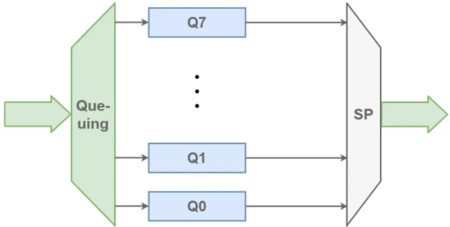
As mentioned before, the number of queues for one bridge port that have different type of priorities ranges between one and eight. If there is one queue all ready messages are queued in the same queue and arbitrated in the FIFO order. Eight queues can be configured on one bridge port allowing a different queue for each of the eight different priority levels of messages, that is determined by the PCP value. The number of queues corresponds to the number of distinct traffic classes. Each traffic class will have an arbitrary transmission selection algorithm and scheduled timing window. Messages that fall in one of the eight traffic types can be grouped to match the number of traffic classes. This mapping from traffic type to traffic class is the process of queuing frames, shown in Figure 4. IEEE recommends a default priority to traffic class mapping given in Table 4. The
reasoning behind such frame classification is given in Annex I of the IEEE 802.1Q Bridges and Bridged Network Amendment [13].
Number of available traffic classes
1 2 3 4 5 6 7 8 P 0 0 0 0 0 0 1 1 1 r 1 0 0 0 0 0 0 0 0 i 2 0 0 0 1 1 2 2 2 o 3 0 0 0 1 1 2 3 3 r 4 0 1 1 2 2 3 4 4 i 5 0 1 1 2 2 3 4 5 t 6 0 1 2 3 3 4 5 6 y 7 0 1 2 3 4 5 6 7
Table 4: Recommended priority to traffic class mapping [13]. The elements in the table represent the queue ID to which each priority is mapped, depending on the number of available queues.
The selection for frame transmission between traffic classes in purely based on queue priority hence the transmission selection algorithm is called the Strict Priority algorithm. Although prioritisation makes a distinguishment between more and less time-critical traffic, it does not give time predictability guarantees even for the highest-priority traffic. Prioritisation alone is not enough to eliminate lower-priority blocking caused by the less time-critical traffic frame transmission. If a switch starts to transmit a frame on its port, this transmission cannot be interrupted, not even by highly time-critical traffic. The high-priority traffic frame has to wait in the switch buffer for the ongoing transmission to finish. This phenomenon is called the buffering effect in the switch. The effect is inevitable with standard Ethernet-based networks and causes non-determinism. Such non-deterministic behaviour is not an issue for certain applications used in environments like office infrastructures where networks are used for file and email transfer. These applications don’t depend on timely delivery of Ethernet frames. However, in automation and automotive car industries, Ethernet-based networks are used for safety applications and closed-loop control, so timely delivery is of utmost importance. AVB/TSN extends the standard Ethernet-based network with real-time capability by introducing mechanisms, like time-triggered scheduling, that ensure timely delivery with soft and hard real-time requirements.
2.3.3. IEEE 802.1Qav - Forwarding and Queuing Enhancements for Time-Sensitive Streams
IEEE 802.1Qav Forwarding and Queuing Enhancements for Time-Sensitive Streams defines traffic shaping based on credit-based fair queuing. The selection for frame transmission is based on the queue priority as well as the credit value the queue has. Assigning a Credit-Based Shaper algorithm to a queue separates it into either traffic class A (tight delay bound) or traffic class B (loose delay bound). The Credit-Based Shaper transmission selection algorithm is supported in addition to the strict priority algorithm. Credit, measured in bits, is accumulated to queues as they wait for there frames to be transmitted and is spent by queues while their frames are being transmitted. The rate of credit accumulation and release can be adjusted on a queue-by-queue basis to produce a weighted queuing behavior. The accumulation rate is called idleSlope and is considered while the queue is waiting to be served, and the release rate is called sendSlope and is considered as the queue is being served, meaning its frames are being transmitted. Both idleSlope and sendSlope represent the rate of change of credit, in bits per second. The credit value sets an additional condition for transmission selection on queues that support the Credit-Based Shaper algorithm, as only queues with positive credit are eligible for transmission. It removes bursts in traffic and provides fair scheduling for lower priority queues, by limiting the allocated bandwidth fraction of CBS queues. This bandwidth fraction is given as:
bandwidthF raction = idleSlope
portT ransmitRate (1) where portTransmitRate is the maximum transmission data rate provided by the MAC Server to the port supporting the egress queue. The value of idleSlope for the queue associated with traffic class N is equal to the operIdleSlope(N) parameter11and can never exceed portTransmitRate. The operIdleSlope(N) is the actual bandwidth, in bits per second, that is currently reserved for use by the corresponding queue and is calculated based on the Stream Reservation Protocol depending on the usage of allocated bandwidth of all the queues supporting one port. The idleSlope parameter, in conjunction with the size of the frames that are being transmitted using the queue, and the maximum time delay that a queue can experience before it is able to transmit a queued frame places an upper bound on the burst size that can be transmitted from queues that use the algorithm [13].
On the other hand, the sendSlope is negative and determined by the idleSlope as given with the Equation 2:
sendSlope = idleSlope − portT ransmitRate (2) Figure 5 illustrates how the credit-based shaper operates in various conditions. The first timing frame (noted with yellow background) illustrates the frame transmission without frame latency while the other parts illustrate different reasons for frame latency, in the middle part (noted with green background) it is due to conflicting frames, and in the last part (red background) it is due to burst regulation. In the first time frame of the graph a message that is class A is queued as ready for transmission, and it is transmitted right away as the bridge port was idle at the moment of the message’s arrival. As the message is transmitted, the credit is decreasing at the sendSlope rate. When the message has been transmitted, as there are no new messages of traffic class A and its credit is less than zero, no messages are being transmitted. The credit increases by the idleSlope rate and when it reaches the value of zero, it stays on that value as there are no messages ready for transmission. Then a conflicting frame starts being transmitted on the bridge port. As the conflicting frame is being transmitted another message of traffic class A is ready for transmission and the credit is not negative. But this time there will be latency and the conflicting frame can not be preempted. In this period of latency the credit increases at the idleSlope rate. After the conflicting frame has finished its transmission, the class A message can be transmitted resulting in a decrease of credit at the sendSlope rate. This time a positive value of credit is left even after the message transmission has ended, and as there were no other messages ready the value of credit was reset to zero. In the following time frame we again have a conflicting frame, but this time there is a burst of ready messages that can start transmission when the conflicting frame is finished. The
11NOTE - The idleSlope value is equal to the operIdleSlope(N) if the queues are not time-aware scheduled. If the
Figure 5: Credit-Based Shaper Algorithm operations in different conditions
messages will be transmitted in a FIFO order starting with M1, reducing the credit. As long as the credit is zero or positive, the messages can be eligible for transmission. In the figure the credit is positive when M2 has started transmission and becomes negative by the time it is transmitted. As the credit has a negative value, no other messages from the queue can be selected for transmission. The credit will start increasing as there are more ready messages that are not being transmitted, but as long as it is negative the port is free to be utilized by lower-priority queues. If a continuous stream of frames is made available to the shaper algorithm, i.e., there is always one frame queued awaiting transmission when the credit value reaches zero, the shaper will limit the burs transmission giving a fair chance for lower-priority traffic classes. Figure 6 illustrates the Transmission Selection Algorithm logical location in the switch from a software architectural perspective.
Figure 6: Software Architecture of the Bridge with the Credit-Based Shaper Algorithm
Although the Credit-Based Shaper provides fair scheduling for low-priority packets, eliminates frame loss and smooths out traffic by removing traffic bursts, unfortunately average delay increases. The recommended mapping of priorities onto traffic classes, and the choice of traffic classes that support particular transmission selection algorithms, is defined in the IEEE Amendments. It follows the principle that all traffic classes that support the credit-based shaper algorithm have higher priority than the rest of the traffic classes, for the algorithm to operate as intended. This is possible by regeneration of priorities.
2.3.4. IEEE 802.1Qbv - Enhancements for Scheduled Traffic
The key to providing on-time delivery of TSN frames is 802.1Qbv. This standard defines a means to transmit certain TSN Ethernet frames on a schedule while allowing non-time-critical TSN Ethernet frames to be transmitted on a best effort basis around the time-critical TSN frames. Time-critical traffic is mostly frames carrying control data in industrial and automotive control applications [14]. As the bandwidth occupied by time-critical traffic is often low, and the cost of providing a dedicated control network can be high, it can be desirable to transmit time-critical traffic with other classes of traffic in the same network, as long as the timing requirements of the time-critical traffic is met. Because of timing synchronization of all the network elements, end devices and bridges implementing IEEE 802.1Qbv can deliver critical communication very quickly and with no discernible jitter in delivery.
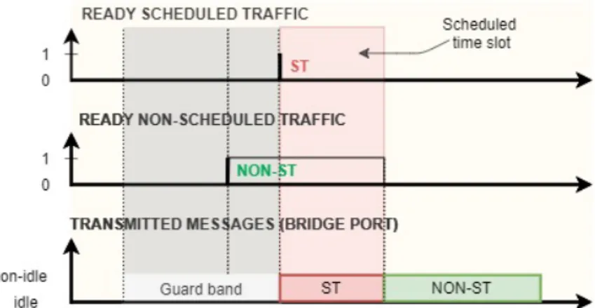
TAS utilizes a gate driver mechanism that opens/closes according to a known and agreed upon schedule, for each port in a bridge. In particular, the Gate Control List (GCL) represents this schedule with binary values, 1 or 0 for open or close for each queue, respectively. If the gate is open, that means that frames can be selected for transmission as long as they satisfy the conditions of the transmission selection algorithm associated with the queue. If the gate is closed, the queued frames in the associated queue can not be selected for transmission. In an implementation that does not support enhancements for scheduled traffic, all gates are in a permanently open state. The GCL is executed periodically, and this period is called the gating cycle. The gate mechanism ensures that, at specific times, only one traffic class or a set of traffic classes has access to the egress port. However, to ensure that the remaining traffic classes cannot affect the transmission of the scheduled traffic class, it is necessary to stop its transmission sufficiently in advance. The transmission of non-scheduled traffic has to finish its transmission before the time slot that is reserved for scheduled traffic. This time slot is called protected time slot or protected window. It is important that the last unprotected transmission has completed before protected transmission starts as preemption is not possible. In the worst case, this would mean that the last unprotected transmission would start a maximum-sized frame transmission time before the start of the protected window. This is implemented by adding a guard band just before the protected time-slot. Frame transmission is not permitted during the guard band, and the egress port is in idle state.
Figure 7: Time-triggered scheduled traffic transmission
Figure 7 illustrates an example where a non-scheduled frame arrives during guard-band. Without the guard band if the frame started transmission, it would not finish before the start of the pro-tected time-slot, resulting in the scheduled frame not starting transmission as scheduled and having possibly unacceptable latency. However, with the guard-band the frame does not start transmission until the scheduled traffic has finished transmission. In general, the length of the guard-band is the size of the largest non-scheduled traffic frame in the switch [14]. From the microseconds perspective, this is the time needed for transmitting a Ethernet frame of size 1542 bytes, and it depends on the network transmission rate. However, the start of the guard band does not need to be fixed if the implementation can determine, from the size of the next queued non-time-critical frames, that
there is sufficient time for a frame to be transmitted in its entirety before the start of the protected traffic window. This means being able to calculate frame transmission times in run-time. A more detailed description can be found in Annex Q if the IEEE Amendment [14].
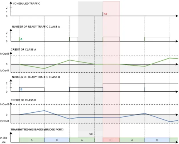
The operations of the credit-based shaper algorithm differ if the switch supports the enhancements for scheduled traffic. Figure 8 illustrates the change of credit if combined with time-aware schedul-ing12.
Figure 8: Operation examples of the CBS with TAS
The credit-based shaper algorithm switches that do not support the enhancements for scheduled traffic, are implemented so that if the queue is not being served, the credit when negative always increases. Now with the support of enhancements for scheduled traffic the algorithm operations are different when it is in the guard band time frame or in the protected window. Here the value of credit stays constant. If a frame is short enough to enter the guard band, the credit will decrease until the frame is being transmitted even if it is happening in the guard band. However, when the transmission is finished, the credit does not follow the usual behaviour (no ready frames - credit reset to zero, credit negative - increase, new ready frames - continue transmission - credit decrease). Instead, the credit value is constant until the end of the protected window.
The idleSlope value has a different definition if the switch is enhanced with time-aware scheduling. It is defined with Equation 3:
idleSlope = operIdleSlope(N ) · OperCycleT ime
GateOpenT ime (3) where OperCycleTime is the operational value of the gating cycle, and GateOpenTime is equal to the total amount of time that the gate of the queue N is opened during the gating cycle [14]. In switches that do not support time-aware scheduling, as mentioned before, the gate is always open, so the total amount of time of the gate being opened in the gating cycle is precisely the gating cycle implying that the idleSlope = operIdleSlope(N) as defined in chapter 2.3.3..
Implementing the Time-Aware Scheduler from a software architecture perspective is illustrated in Figure 9, as the Gating Mechanism.
Figure 9: Software Architecture of the Bridge with Time-Aware Scheduler
2.3.5. IEEE 802.3br and 802.1Qbu Interspersing Express Traffic (IET) and Frame Preemption
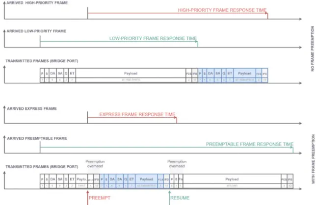
One of the key challenges in future Ethernet-based automotive and industrial networks is high port utilization and low-latency transport of time-critical traffic. Sending Ethernet frames non-preemptively introduces a major source of delay, as in the worst-case, a time-critical high-priority frame might be blocked by a non-time-critical frame, which started transmission just before the time-critical frame. Hence, a time-critical high-priority frame can be delayed by a frame of lower-priority. The IEEE Std 802.3br and IEEE Std 802.3bu introduce Ethernet frame preemption to address this problem. Frame preemption is the suspension of the transmission of a preemptable frame allowing one or more express frames to be transmitted before resuming transmission of the preemptable frame [15].
The IEEE working groups 802.1 and 802.3 collaborated to specify the frame preemption technology since the technology required both changes in the Ethernet Media Access Control (MAC) layer that is under the IEEE 802.3 Working group, as well as changes in the bridge management protocols that are under the IEEE 802.1 Working group. Hence, frame preemption is described in two different standards documents: IEEE 802.1Qbu13for the bridge management component and IEEE
802.3br14for the Ethernet MAC component.
13IEEE 802.1Qbu:Available from [Online]: https://ieeexplore-ieee-org.ep.bib.mdh.se/document/7553415 14IEEE 802.3br: Available from [Online]: https://ieeexplore-ieee-org.ep.bib.mdh.se/document/7592835
The frame preemption mechanism, on the physical level, is specified in the Interspersing Ex-press Traffic (802.3br) standard, while the management and configuration mechanisms for frame preemption are specified in the Frame Preemption (802.1Qbu) standard. To facilitate one-level frame preemption IEEE 802.3br working group separates a given bridge egress port into two MAC service interfaces, namely preemptable MAC (pMAC) service interface and express MAC (eMAC) service interface, as shown in Figure 10. The MAC Merge Sublayer supports interspersing express traffic with preemptable traffic. This is achieved by using a MAC Merge Sublayer to attach an express Media Access Control (MAC) and a preemptable MAC to a single Reconciliation Sublayer (RS) service.
Figure 10: Preemptable MAC (pMAC) and express MAC (eMAC) scheme [2]
Each Ethernet traffic class is mapped to either the express or the preemptable MAC interface. Frames of express classes cannot be preempted and preemptable frames cannot preempt regardless of their priority. Particularly, preemptable frames cannot be preempted by other preemptable frames, and express frames cannot preempt other express frames. Express frames may preempt only preemptable frames. Preemption can occur only between an express and a preemptable frame, where the express frame has higher priority than the preemptable frame. When preemption occurs the transmission of the preempted frame is resumed first than when the express frames have been completely transmitted. A preemptable frame can be preempted multiple times. When frames are preempted they are split into fragments and are reassembled in the MAC layer so that when sent to the Ethernet’s physical layer, they are complete frames. These complete frames transmit the split payload and have slightly different formats so that the first, middle and last fragment of the preempted format can differ. Ports supporting frame preemption, transmit frames where start frame delimiter SFD byte, is replaced by either:
• SMD-E for express frames,
• SMD-Sx for the start fragment of the preemptable frame or • SMD-Cx for the continuation fragment of the preemptable frame
Continuation fragments also have one byte less for the preamble that is used for the FCnt byte that is the fragment counter. For preemptable frames, the CRC sum 4-byte field that is at the end of the frame followed by a IFG, for the exception of the last fragment is MCRC instead of FCS. The last fragment is terminated by FCS, as is the express frame. Another difference in frame format between preemptable frame fragments is that, except the start fragment, there is no need to transmit the source and destination MAC address, or the Q-Tag and Ethernet type as this one-level preemption and only one frame can be preempted at a time.
This implies that the payload of the continuation frames has to be at least 60 bytes, compared to the 42 bytes of the start fragment, to meet the minimum Ethernet frame size of 84 bytes. The minimum frame size requirement imposes a constraint on the preemption mechanism; a preemption cannot happen if the frame or its continuation fragment would be split into two fragments that do
not fulfill the minimum frame requirement. This constraint causes a possible express frame latency. The smallest frame that can be preempted has the payload of 102 bytes, as these can be split into 42 bytes and 60 bytes to form a start and continuation fragment that fulfill the minimum Ethernet frame size. A frame with 101 byte payload is the worst-case frame that cannot be preempted, and will cause the maximum express frame latency. The whole frame size, together with the preamble (7), SMD-Sx(1), DA(6), SA(6), Q-Tag (4), ET(2), FCS(4) and IFG(12) is 143 bytes [16].
In a switch that does not support the preemption mechanism, in the worst-case, a high-priority frames can be delayed by about 123,36 µs per 100 Mbps switch by lower-priority frames. The worst-case is where the high-priority frame is blocked by the maximum size low-priority frame of 1542 bytes, because under non-preemptive frame transmission, a frame, which is in transmission, is guaranteed to finish without interruption. This might be too much for time-critical control applications [16]. With frame preemption the maximum high-priority frame latency due to lower-priority blocking is reduced to about 10,16 µs per 100 Mbps switch. Frame preemption, however, also causes an additional delay for preempted frames caused by the preemption, the preemption overhead, which can potentially have a negative impact on the performance, depending on the circumstances. The preemption overhead is caused by an additional 24 bytes per preemption, that are being sent. This causes a latency of around 1.92 µs per 100 Mbps switch. In a 10 Gbps switch the delay is lowered from around 1 µs to 0.01 µs. The 123,36 µs in a 100 Mbps switch and the 1,23 µs for a 10 Gbps switch are the upper bounds on the additional delay before a MAC Client can send an Express frame when preemption capability is not used. At higher operating speeds the additional delay gets smaller in proportion to the speed. The preemption capability is most useful at lower operating speeds. At higher operating speeds this additional delay gets smaller in proportion to the speed, reducing the advantage of the preemption mechanism.
Figure 11: Preemption Mechanism Trace Example
Meeting time-critical transmission requirements has been introduced with the gating mechanism, but the time-scheduling of traffic also introduced guard-bands. They cause high latency for non-scheduled traffic and ineffective utilization of the network as there is a significant length of time during which no frames can be transmitted. The purpose of this amendment is also to reduce this latency caused by guard-bands. The guard-band is used so that the scheduled traffic will be
Figure 12: Hold and Release mechanism enabled vs. disabled
transmitted without interference. If the preemption capability is used preemptable frames cannot interfere and block express traffic. As we noted above the worst-case lower-priority blocking that an express frame can suffer is the transmission duration of the maximal length of a non-preemptable fragment. To ensure that the scheduled traffic cannot experience this blocking it is enough to introduce a reduced guard-band. This reduced guard-band is an explicit 127-byte guard-band implemented with the Hold and Release mechanism. This mechanism will generate a Hold signal 127-byte time before the protected window to preempt the lower-priority frame. In the case where at the moment the Hold signal is sent, the frame length that is not transmitted is 127 bytes or less preemption will not be possible as this end fragment is non-preemptable. Still, thanks to the Hold signal the preemptable frame fragment will finish transmission before the arrival time of scheduled data. If the untransmitted preemptable fragment was bigger, it would be preempted and there would be a small port utilization loss. But this loss is smaller than it would be without the preemption mechanism, where the standard guard-band is used instead of the reduced one. The Release signal is generated to signal the end of the protected window so that the preempted frame can continue transmission.
The result of using scheduling, HOLD/RELEASE and preemption in combination is that the express traffic’s protected window can be completely protected from interference from preemptable traffic, while at the same time reducing the impact of the protected window on the amount of bandwidth that is available to preemptable traffic.
3.
Related Work
In this section, besides examining the state-of-art of the Frame Preemtion Standard in Section 3.3., we also examine the other key components of TSN individually in Section 3.2., and as a whole in Section 3.1. The first section also takes the alternatives to TSN into account, in terms of hard real-time networks. In related work we describe research and extensions relevant to Ethernet TSN and the preemption mechanism, also we provide a brief overview of existing performance analysis approaches for TSN networks and some experiment results relevant to TSN. Most works we reference are simulation-based experiments similar to our work.
3.1.
Performance evaluation of real-time Ethernet Standards
In the work by Paula Doyel [17] several existing real-time solutions are evaluated. The existing real-time solutions, whose advantages and disadvantages are addressed, include EtherNet/IP, PROFInet, EtherCAT and ETHERNET Powerlink. This work is of the first research papers that deal with real-time Ethernet and it served as a base for many following research papers. It also introduced then new IEEE 1588 standard that ensures time synchronization. Performance analysis of the IEEE Std. 802.1 Ethernet Audio/Video Bridging standard has been explored in multiple works, one of them being by Lim et al. (2012) [18] who analyze the AVB standard based on a simulation approach. Ashjaei et al. (2017) [19] discusses modeling and analysis of AVB communication network within a model- and component-based software development framework. Similar performance analysis and system modelling of vehicle Ethernet communication has been done by Jiaheng Qiu [20]. Mubeen et al. (2019) [21] presented the first holistic modeling approach for TSN in model- and component-based software development network. They explicitly modeled the timing requirements imposed by TSN-based communication. Based on these models they present a end-to-end timing model for TSN-based networks of distributed embedded systems. The work by Bello et al. [22] gives an up-to-date overview of the modern technologies concerning distributed embedded systems. In the work TSN is discussed among others. The existing and future automotive software development solutions are the focus of the work. The work concludes that the TSN is the key for future automotive feature development, like autonomous driving. This gives the motivation for further investigation and ultimately for this thesis. The work by Nasrallah et al. [2] is an excessive survey on Ultra-Low Latency Networks including The IEEE TSN and IETF DetNet Standards. They have identified the pitfalls and limitations of the existing standards for networks that need low-latency and research studies on those. This survey can thus serve as a basis for the development of standards enhancements and future Ultra-Low Latency research studies.
3.2.
Performance analysis of individual TSN standards
Patti and Bello [12] have done a performance analysis in 2019, of the IEEE 802.1Q standard that is one of the base standards of Time-Sensitive Networking. They have done a quantitative evaluation of the network performance in terms of maximum end-to-end delays and absolute jitter, compering different network configurations and traffic patterns. The analysis results are obtained using the OMNeT++ framework. The work in [23] focuses on the simulation approach performance analysis of TSN IEEE 802.1Qbv and IEEE 802.1Qbu standards. Performance is analyzed and measured in terms of end-to-end transmission latency and link utilization, through five scenarios. Other work focuses on the effects of combining TAS with credit-based shaping [24] and [25]. Schedule synthesis is required, e.g., to implement a TDMA scheme with TAS. In the context of TAS, this schedule is referred to as Gate Control List (GCL). The calculation of GCLs for stream-based scheduling is challenging because it is, in general, an NP-hard problem, and is often solved by constraint-based programming or heuristics [26].
3.3.
Evaluation of TSN with Frame Preemption
Jia et al. (2013) [27] work presented a simulation-based evaluation of the IEEE 802.3br standard. The paper compares the IEEE 802.3z Gigabit Ethernet networks with applied IEEE 802.1Qbu frame preemption mechanism with the existing non-preemptive-based priority scheduling schemes. The results confirm that using frame preemption mechanism reduces the end-to-end latency and
absolute jitter of time-critical traffic. The same year in Germany an experiment-based evaluation of the frame preemption mechanism was published. The work by Kim et al. [28] proposes a custom preemption mechanism and implement a controller based on that preemption mechanism. The implementation results show that latency and jitters time-critical traffic are reduced when compared to a non-preemptive Ethernet controller. Thiele and Ernst [16] have done an analysis on Ethernet under preemption in 2016. They present a formal worst-case performance analysis of Time-Sensitive Networks with frame preemption. Using a realistic automotive Ethernet setup they derived worst-case latency bounds under preemption. They also compared the worst-worst-case performance of standard Ethernet and Ethernet TSN under preemption with the worst-case performance analysis results of non-preemptive implementations of these standards. To the best of our knowledge, this is the only work that analyses specifically the TSN preemtion standard to derive worst-case performance bounds, hence it is very important work for this thesis as we are analysing the performance of a networks with multiple frame preemtions. A recent study [29] (2020) discusses different ways of using TAS and the preemption mechanism. They present the drawbacks and advantages between stream-based TAS, class-based TAS, and frame preemption. A simulator-based comparison of these mechanisms was conducted using the TSN network simulation tool NeSTiNg, for different scenarios. Moreover, they introduce calculation formulas for class-based scheduling.
3.4.
Existing network simulators
There are existing TSN simulators like NeSTiNg15 or CoRE4INET16, that have already been
developed. Both of these are simulation models in a bigger simulation environment. They were developed in the open-source INET Framework17, which is a model library that supports a wide
variety of networks and is especially suitable for researcher and students working with communication networks. It offers different models, link layer protocols, routing protocols, sensor protocols and many more components. Besides evaluation, it can be used for designing and validating new protocols. INET Framework generates simulation models for the OMNeT++ Simulation IDE18.
The OMNeT++ Environment provides the simulation kernel and other libraries for network description, simulation configuration and simulation results recording.
CoRE4INET is one of the INET Framework extensions that support the TSN components. It is an event-based network simulator of real-time Ethernet. It was first introduced in 2011, as TTE4INET [30], as it supported TTEthernet. When more real-time Ethernet protocols were added the project was renamed from TTE4INET to CoRE4INET, published in [30], to show that it does not only contain time-triggered protocols. The simulator supports:
• Best Efford Crosstraffic
• IEEE 802.1Q / IEEE P802.1p VLANs and Priorities • Time-Sensitive Networking (TSN)
• IEEE 802.1 Audio/Video Bridging (AVB) • TTEthernet (AS6802)
• IP over Realtime-Ethernet
Another simulation model extending INET Framework to support the TSN components is NeST-iNg. It supports frame tagging, different shaper components and the preemption mechanism. The model was initially developed by a group of students during a curricular project and is continuously extended at the Distributed Systems group of IPVS, University of Stuttgart. David Hellmanns, one of the simulation authors, introduced NeSTiNg at the September 2018 IEEE 802.1 Working Group interim meeting in a presentation [31]. The paper [32] published in 2019 describes the NeSTiNg simulator.
Although the performance analysis could have been done using the OMNeT++ environment and
15NeSTiNg Open Source Code: Available from [Online]: https://gitlab.com/ipvs/nesting
16CoRE4INET Open Source Code: Available from [Online]: https://github.com/CoRE-RG/CoRE4INET 17INET Framework: Available from [Online]: https://inet.omnetpp.org
one of the developed TSN -supporting simulation models, we decided to build one from scratch. This gives us the complete freedom to manipulate every aspect of the network and the possibility of writing a simple code targeting the specific features we want to evaluate. Nevertheless, the TSN-specific simulation models should be mentioned as an inspiration for the development of some model parts in TSNS.
3.5.
Discussion
From investigating the related work, we can conclude that the major part that is missing in the body of knowledge of the preemption mechanism, is the analysis for different preemption configurations. Most works that do a simulation-based analysis are limited to simulators that do not support multiple express traffic classes as the network behaviour in such an environment is not known or as it not the focus of the work and as it would have to be investigated as a separate work. That analysis will be done in this thesis, as well as the introduction of the custom simulator tool that focuses on various preemption configuration patterns in a TSN network.
4.
Method
The most suitable research method is an experimental method since the purpose of the thesis is to design and implement a simulation tool for TSN and do a performance analysis based on it. Computer science as a relatively modern science discipline investigates in new and better solutions broadly using an experimental method as it is suited for evaluation. As explained by Amaral [33], the experiment is often divided into two phases: exploratory phase and the evaluation phase. The exploratory phase refers to the body of knowledge and helps identify what the questions are that should be asked about the system under evaluation, whereas in the evaluation phase those questions will attempt to be answered. In the exploratory phase the important step of the literature review is done as it will establish the knowledge of the research topic, identify the state-of-the-art in the field, and put the research in the context of the larger body of work by critically assessing the existing articles, conference proceedings, books, and other publications. The published work is not just summarised but also evaluated to understand the open research questions in the field and show the relevance of the thesis research. In Figure 13, based on the framework of research from Nunamaker, Chen and Purdin [3], the two phases are shown graphically.
Figure 13: Research framework [3]
Nunamaker, Chen and Purdin [3]. Many experiment that are conducted in the computer science discipline and research studies based on these experiments are lacking validity and relevance because of the careless fashion in which the experiments were conducted and reported, as noted by Amaral [33].
A good experimental research study follows these conventions, as advised by Jose Nelson Amaral [33]:
• Record keeping: Labeling and filing the results in ways that will make it possible to retrieve and check them later, as an experiment has to be ”replicable”. Annotating, filing, and documenting are essential for the future relevance of an experimental study.
• Experimental setup design: Documenting the findings after the exploratory phase, as well as redefining the research question and experiment setup as greater knowledge is obtained. • Reporting experimental results: The report should be thorough and transparent. The
numerical results presented should also be accompanied by a carefully written discussion of the results. This discussion should provide insight into those results and contribute to the body of knowledge.
The independent and dependent variables will be specified after the exploratory phase. According to Farkas [34], several performance metrics can be tracked, to test the performance of the network, such as data transport latency, delay variation and data loss. The performance analysis will be done first by an investigation, followed by the simulation on multiple scenarios. The more experiments completed, the stronger the principle is for the hypothesis. It is also a good practice to have several replicate samples for one case for variability estimation.
The steps towards finishing this thesis are:
(1) Investigation of the TSN related standards and research on the TSN mechanisms
(2) Investigation of the related work on preemption support for Etherenet and in particular for TSN
(3) Analysis of the available simulation frameworks for TSN
(4) Investigate the effects of defining multiple express traffic classes on the overall network performance
(5) Using a network simulator to experiment with multiple cases to showcase the effects of having more express traffic classes
(6) Results analysis and report writing
To understand the state-of-art excessive study on the relevant TSN standards will be conducted as well as the review of related works. The results of the literature review will be summarised in the background section, and the existing work on the subject will be mentioned and explained in the related works section. This is the primary step towards developing a TSN-supporting network egress port simulator, along with analysing the existing simulators. For the development of the network simulator, an already developed basic simulator will be used. The basic simulator supports one fixed network configuration where one ST traffic is express, accompanied by three preemptable traffic classes. The basic simulator supports the synchronised time and the FIFO logic of queues, as well as the credit-based shaper for the two middle-priority queues. To upgrade the simulator so it can support any traffic configuration pattern, we will implement the possibility of having different queue numbers that can be assigned any transmission selection algorithm (the option to support the credit-based shaper or not), the automated calculation of the idleSlope, the gating mechanism of the Time-Aware Scheduler, so that any traffic class can be scheduled, and enable any class the possibility to be express, taking into account the different behaviour in terms of guard-bands. The basic simulator is written in C, as well as the upgraded simulator will.
To calculate the performance of an egress port model in a sinlge-node network we will calcu-late the wait time of each traffic frame. As preemption affects the time needed for a traffic frame to transmit, as it can interfere with a transmitting frame, the response time of a frame in the egress port will also be computed. Both terms are defined in the beginning of Sec. 6. These will be the output values of the simulator. To get relevant results, we will suggest possible scenarios that could show the effects of the preemption mechanism. Some scenarios will have a fixed traffic configuration and fixed traffic stream set to evaluate an specific expected outcome, other scenarios will have a fixed traffic configuration pattern and randomly generated traffic stream sets in order to evaluate the effects of these traffic configurations regardless of the message set, but rather on the configuration itself. To eliminate the influence of the traffic stream set, a sufficient number of simulations will be run for one configuration. As networks in industrial environment mostly transmit a large number of traffic data, taking in consideration the large number of simulations, the results will not be shown for each traffic stream individually but rather in a compact form. The delay computation will be done for each traffic class with the best-case, worst-case and average value over all the simulation.
5.
Ethical and Societal Considerations
This work does not contain any ethical research issues. At the very least, the issues can not be found at this moment of the research. The research is done in hopes to bring new insight into the frame preemtion standard of time-sensitive networks that make networks real-time capable in a standardized way. It is purely a scientific experiment done in a simulated environment without yet known future impact on the economy, political, social and ecologically sustainable development.
![Figure 2: Master-slave architecture for time synchronisation in IEEE Std 802.1AS [1]](https://thumb-eu.123doks.com/thumbv2/5dokorg/4831413.130407/12.892.215.675.127.391/figure-master-slave-architecture-time-synchronisation-ieee-std.webp)


![Figure 13: Research framework [3]](https://thumb-eu.123doks.com/thumbv2/5dokorg/4831413.130407/25.892.259.632.771.1077/figure-research-framework.webp)
