Department of
Biology and Chemical Engineering
Halfsphere Derivatisation of Magnetic Micro particles
Nadea Dilanson
Degree Project, ECTS 30,0 At Mälardalens University Department of Biology and Chemical Engineering Eskilstuna, Sweden, 2006
Supervisor at Mälardalen’s University
Prof. Sven Oscarsson
Examiner at Mälardalen’s University
2
Abstract
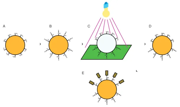
This exam project is an effort to derivatize one side of magnetic beads with one kind of molecule , and another one on the opposite side. First the surface of the sphere is loaded with a suitable linker with, e.g. amino or hydroxyl groups. In the second step, these groups are derivatized with a photosensitive protecting group such as Nitroveratryloxycarbonyl. In the third step, the particles are placed on a surface and then irradiated with UltraViolet light (320 nm) from above, which will cleave off the Nitroveratryloxycarbonyl on the upper half, while leaving in place the ones at the lower half. The linker groups of the upper half can now be derivatized by other reagents of choice. The remaining Nitroveratryloxycarbonyl groups can be removed by suspending the particles in a solvent and then exposing them to UltraViolet light. Finally the linker groups on this half of the particles can be derivatized by a second reagent.
Magnetic particles were marked with FITC, two different kinds of magnetic particles were selected, sikastar-NH2 function and sikastar-COOH function. Five different solvents were used to wash the magnetic particles and remove the bounded FITC, solvents are Acetone, 1-butanol, DMSO, 4-propanol, and Urea. Magnetic particles sikastar-NH2 and sikastar-COOH were
washed with Tween 20 and SDS to remove non-specific binding of FITC. Sikastar particles were treated with IgG*FITC in constant presence of the following solvents: PBS*10, Pluronic-F127, Tween 20. Pegylation of sikastar particles got done to reduce non-specific binding. Derivatisation of Nitroveratryloxycarbonyl got done and specific bindning of IgG*FITC to micromer particles got done by protein thiolation.
When a different concentration of FITC was tested to control specific and non-specific binding to sikastar functions, we observed that we had a specific binding to sikastar-NH2 in the lowest
concentration. In choice of magnetic particles we had specific binding with sikastar-NH2. Using
a different solvents Acetone, 1-butanol, 4-propanol, and Urea
to remove bounded FITC, sikastar-NH2 showed stronger fluoresence than sikastar-COOH after washing because of
specific binding and it was difficult to remove FITC with Acetone, 1-butanol, 4-propanol,and Urea, on the other hand DMSO could remove bounded FITC from sikastar particles. When we washed magnetic particles sikastar-NH2 and sikastar-COOH with Tween 20 and SDS to remove non-specific binding of FITC, we could see that magnetic particles showed fluoresence in both functions due to non-specific binding. When sikastar particles got treated with IgG*FITC in constant presence of solvents PBS*10, Pluronic-F127, and Tween 20, we had a specific binding between sikastar particles and IgG*FITC in a presence of pluronic-F127. Pegylation of sikastar particles with a different kind of a PEG was possibl to reduce non-specific bindning. The derivatisation of Nitroveratryloxycarbonyl could be done in a N2
environment, and Nitroveratryloxycarbonyl-sikastar-NH2 could be radiated with UltraViolet
light to remove Nitroveratryloxycarbonyl. Also thiolation method could be used to perform specific binding of IgG*FITC to micromer particles.
3
Table of contents
1.Introduction………...4
2. Materials and methods………...10
2.1 Chemicals………...10
2.2 Aparatus………...11
2.3 Methods………...12
2.3.1 Optimization:step1: ( Magnet particle marked with FITC)...12
2.3.2 Optimization:step2: (Choice of magnet particle)...12
2.3.3 Optimization:step3: (Washing magnet particles with different solvents to remove bounded FITC)...13
2.3.4 Optimization:step4: ( Washing magnet particles with detergent to remove non-specific bindning of FITC)...13
2.3.5 Optimization:step5: (Treatment of magnet particles with IgG*FITC in constant presence of different solvents)...13
2.3.6 Pegylation of sikastar particles to reduce non-specific binding...14
2.3.7 Chemical derivatization:(NVOC of sikastar-NH2 in the Atmos Bag)...15
2.3.8 Specific bindning of IgG*FITC to micromer particles...16
3.Results and Discussion………...17
3.1 Optimization:step1: ( Magnet particle marked with FITC)...17
3.2 Optimization:step2: (Choice of magnet particle)...18
3.3 Optimization:step3: (Washing magnet particles with different solvents to remove bounded FITC)...18
3.4 Optimization:step4: ( washing magnet particles with detergent to remove non-specific bindning of FITC)...19
3.5 Optimization:step5: (Treatment of magnet particles with IgG*FITC in constant presence of different solvents)...19
3.6 Pegylation of sikastar particles to reduce non-specific binding...20
3.7 Chemical derivatization: (NVOC of sikastar-NH2in the Atmos Bag)...21
3.8 Specific bindning of IgG*FITC to micromer particles...22
4. Acknowledgements………......23
5. Abbreviations………...24
6. Reference list………...26 7. Appendix………...
7.1 Instruments used in library 7.2 Microscope pictures
7.3 Derivatization of one half of a sphere
7.4 Treatment av magnet particles with IgG*FITC in constant presence of different solvents
7.5 Specific bindning of IgG*FITC to micromer particles 7.6 FITC conjugation with antibody
4
1.
Introduction
This exam project is an effort to derivatize one side of magnetic beads with one kind of molecule , and another one on the opposite side. The possibility exists to create a surface by which e.g. the property of the surface can be changed by rotating the magnetic particles on the surface by rotating the applied magnetic field. Applying this principle, different gradients of hydrophobicity can be created on a surface since the magnetic state of each element can be controlled individually. Since the beads can be derivatised with different molecules of different hydrophobicity, the gradient of hydrophobicity can be established by controlled positioning of the beads. Altrnatively, one side of the surface can be an ion exchanger the other hydrophobic or provided with lectins. These kinds of surfaces are commonly used for molecular separation, which makes it possible to achieve two different separation principles using one and the same surface or changing the characteristics of the separation principle by time. The proposed derivatization of one half of a sphere would be possible as follows. First the surface of the sphere is loaded with a suitable linker with , e.g. , amino or hydroxyl groups. In the second step, these groups are derivatized with a photosensitive protecting group such as Nitroveratryloxycarbonyl (NVOC). In the third step, the particles are placed on a surface and are then irradiated with UltraViolet (UV) light(320 nm) from above, which will cleave off the NVOC on the upper half, while leaving in place the ones at the lower half (in the shade). The linker groups of the upper half can now be derivatized by other reagents of choice. The remaining NVOC groups can be removed by suspending the particles in a solvent and then exposing them to UV light. Finally the linker groups on this half of the particles can be derivatized by a second reagent as showen in fig.1.1. One of the main obstacles of the method is that unspecific interactions will take place when the surface is modified with chemical substances. One way to visualize the hemispheric reaction is by reacting amino groups with Fluorescein-5-IsoThioCyanate (FITC) but the unspecific reaction with the particle surface itself makes it impossible to differentiate between the specific reaction with the amino groups and the unspecific interaction with the surface. One way to solve this problem is by introducing PEG on the surface with terminal amino groups. The pegylated surface lower unspecific interaction with FITC or with biomolecules marked with FITC.
NH2 NH 2 NH 2 NH 2 NH 2 NH 2 NH 2 NH 2 NH 2 NH2 NH NH NH NH NH NH NH NH NH NH X X X X X X X X X X NH2 NH 2 NH 2 NH NH NH NH NH NH 2 NH2 X X X X X NH2 NH 2 NH 2 NH NH NH NH NH NH 2 NH2 X X X X X NH NH NH NH NH NH NH NH NH NH X X X X X A B C D E
5
Magnetic silica particles are produced by hydrolysis of orthosilicates in the presence of
magnetite. They have a hydrophilic surface with terminal Si-OH-bonds, and can easily be separated with conventional permanent magnets. They are extremely stable in organic solvents and at high temperatures, are designed with the surface functionalities OH(plain), NH2, COOH
and epoxy for the covalent binding of proteins, antibodies or other molecules, magnetic silica particles illustrated in (fig.7.2.1) & (fig. 7.2.2).15
Micromer-M are monodisperse particles which consist of magnetite in an organic matrix from a styrene-maleic acid- copolymer. They are finally coated with a polymer layer for the encapsulation of magnetite and the introduction of chemical functionalities, can easily be separated with convertional permanent magnets. They are designed with the surface functionalities NH2 and COOH for the covalent binding of proteins, antibodies or other
molecules as showen in fig.(7.2.2) & fig.(7.2.3).15
Protecting groups is a painful necessity in organic synthesis, despite all the drawbacks
associated with their use. Photolabile protecting groups bring an interesting feature: They don’t require any reagent for their cleavage, just light. This category of protecting groups opens for the possibility of dealing with extremely sensitive molecules, otherwise incompatible with acids or bases. The most popular photolabile protecting group is undisputedly the 6-nitroveratroyloxycarbonyl group(NVOC). It is based on the photochemically-induced photoisomerisation of 0-nitrobenzyl alcohol derivatives into 0-nitrosobenzaldehyde. Photolytic cleavage of a chemical bond is, by essence, the consequence of the absorption of a photon by the substrate, and can occure through a limited number of pathways.16
Intermolecular cross-linking can be used to bind proteins of the same or different kinds to each other (protein-protein conjugation) and to modify cell membranes or other macromolecular assemblies. With this reagent intermolecular cross-linkages can easily be introduced between proteins without the concomitant formation of intramolecular cross-linkages. It should therefore have great potential as a protein-protein conjugation reagent. Unlike most other conventionally used protein-conjugation techniques, reactions involving N-succinimidyl 3-(2-pyridyldithio)propionate (SPDP)can be controlled to give conjugates of different proteins (heteroconjugates), without unwanted cross-reaction products such as the homoconjugates of each of the two proteins. The size of the conjugates can also be reasonably well controlled, e.g. bimolecular, termolecular or polymeric conjugates can be prepared. SPDP also presents a new reagent for the introduction of aliphatic thiols into amino group containing molecules such as proteins.2
Cross linkers are chemical reagents used to conjugate molecules together by a covalent bond. Several atoms separate the 2 molecules, forming the “spacer arm”. The conjugate associates the characteristics and biological activities of each components.
Cross-linkers have become important tools for the preparation of conjugates used in a lot of immunotechnologies, and for protein studies (structure, interactions, activity, degradation..).17
The cross-linkers are used extensively to form enzyme conjugates for use in immunoassays or in labelled DNA probe techniques. N-Succinimidyl-3-(2-Pyridyl Dithio)-Propionate(SPDP) is the most popular heterobifunctional cross-linking agent available. The activated NHS ester end of SPDP reacts with amine groups in proteins and other molecules to form an amide linkage. The 2-Pyridyldithiol group at the other end reacts with sulfhydryl residues to form a disulfide linkage with sulfhydril-containing molecules.14
EDAC(or EDC;1-ethyl-3-(3-dimethylaminopropyl)carbodiimide hydrochloride) is the most commonly used carbodiimide for use in conjugating biological substances. Its water solubility allows for direct addition to a reaction without prior organic solvent dissolution. There are
6 some side reactions that may occure when using EDAC with proteins. In addition to reacting with carboxylates, EDAC itself can form a stable complex with exposed sulfhydryl groups. EDAC may promote unwanted polymerization due to the usual abundance of both amines and carboxylates on protein molecules14, EDAC-HCL structure illustrated in fig.2.1.
Figure 2.1.
1-(3- DIMETHYLAMINOPROPYL)-3-ETHYLCARBODIIMIDE HYDROCHLORIDE
(EDAC-HCl)18
In biology, the isothiocyanate derivative of fluorescein is often used to label and track cells in fluorescence microscopy applications. The fluorescence of this molecule is very high, and exitation occurs at 494nm and emission at 525 nm. The isothiocyanate group(-N=C=S) replaces a hydrogen atom on the bottom ring of the structure, and is reactive with amine groups on proteins inside cells.
Fluorescein isothiocyanate is often abbreviated as FITC (figure 2.2). Additional biologically active molecules (such as antibodies) may also be attached to fluorescein, allowing biologists to target the fluorophore to specific proteins or structures within cells.
Fluorescein is a fluorophore commonly used in microscopy, in a type of dyelaser as the gain medium, and in forensics and serology to detect latent blood stains. 6
Figure 2.2. Fluorescein isothiocyanate (FITC) 6
FITC is a small organic molecule, and is typically conjugated to proteins via primary amines(i.e., lysines). Usually, between 3 and 6 FITC molecules are conjugated to each antibody; higher conjugations can result in solubility problems as well as internal quenching(and reduced brightness). Thus an antibody will usually be conjugated in several
7 parallel reactions to different amounts of FITC, and the resulting reagents will be compared for brightness(and background stickiness) to choose the optimal conjugation ratio. Fluorescien is typically exited by the 488nm line of an argon laser, and emission is collected at 530nm.7
Detergent is a cleansing substance that acts similary to soap but is made from chemical compounds rather than fats and lye.8 Detergents are most commonly classified on the basis of the charge or nature of the hydrophilic portion(head group) and the flexibility or chemical nature of the hydrophobic portion. Head groups can be anionic, zwitterionic, non-ionic or cationic. Anionic head groups are negatively charged moieties such as carboxylate, sulphate or sulfonate. Anionic detergents usually are commercially available as the alkali metal(Na+ or K+)salt form. Zwitterionic head groups contain both a negatively charged moiety and a positively charged moiety; examples are betaines and sulfobetaines. The hydrophobic portions of detergents used in biochemical research are generally straight- or branched-chain hydrocarbons or steroidal moieties.
The straight-chain hydrocarbons are considered the most flexible. The steroidal moieties are relatively rigid.
Several factors can affect detergent performance: - Temperature
- pH
- Ionic strength
- Detergent concentration - Presence of multivalent ions - Purity
- Presence of organic additives
Control of pH is most important when working with ionic detergents.
Anionic detergents are soluble only at a pH greater than the pKa of their ionisable group,
whereas cationic detergents (e.g., primary, secondary, and tertiary amines) are soluble only at a pH less than the pKa . Cationic detergents of the quaternary ammonium type remain soluble at
all pHs.
The largest variety of detergents is used in the isolation and study of integral membrane proteins. Isolation of integral membrane proteins is thought to occur in four steps:
1. Detergent binds to the membrane. 2. Membrane lysis occurs.
3. The membrane is solubilized in the form of detergent-lipid-protein complexes.
4. The detergent-lipid-protein complexes are further solubilized to give detergent-protien complexes and detergent-lipid complexes.9
Sodium Dodecyl Sulfate(SDS) is a detergent (soap) that can dissolve hydrophobic molecules
but also has a negative charge(sulphate) attached to it. Therefore, if a cell is incubated with SDS, the membranes will be dissolved and the proteins will be soluablized by the detergent, plus all the proteins will be covered with many negative charges.1
Sodium dodecyl sulphate (SDS) is an anionic detergent which denatures proteins by "wrapping around" the polypeptide backbone - and SDS binds to proteins fairly specifically in a mass ratio of 1.4:1. In so doing, SDS confers a negative charge to the polypeptide in proportion to its length - ie: the denatured polypeptides become “rods” of negative charge cloud with equal charge or charge densities per unit length.10
Hydrophobic means “water-hating”. Chemical groups that tend to make substances hydrophobic include –CH2 –chains and rings(hydrocarbons).These substances lack the ability to
8 hydrophobic surfaces;rather, the droplets stay beaded up with high values of contact angel. The opposite of hydrophobic is hydrophilic(water-loving)
AtmosBag is a flexible, inflatable polyethylene chamber with built-in gloves that lets you work in a totally isolated and controlled environment. It is an inexpensive, portable alternative to the glove box and is well suited to a variety of tasks and materials. AtmosBag slips over the top of cans and drums to blanket with inert gas and isolate vapors and dusts during sampling operations. Minimizes worker exposure and preserves the integrity of the sampled bulk material.
Specifications:
- Constructed of sturdy 0.003in.gauge polyethylene that is polished for good clarity - Seams are heat-sealed for strength and inflation tested to be leak-free
- Inlet ports are provided on each side for laboratory gas, vacume, and electrical lines - Available non-sterile and sterile, in two-hand and four-hand configurations, with
Tape-seal or Zipper-lock closures
- AtmosBag is not fire-retardant or intended for prolonged contact with solvents, vapors, or chemicals
- Small size has 2 gas ports. All other sizes have 4 gas ports.3
MOPS is the common name for the compound 3-(N-morpholino)propanesulfonic acid, MOPS structure is shown in figure 2.3. It is frequently used as a buffering material in biology and biochemistry. With a pKa of 7.20, Mops is an excellent buffer for many biological systems at
near-neutral pH.11
Figure 2.3. 3-(N-Morpholino)propanesulfonic acid (MOPS)5
Dimethyl Sulfoxide (DMSO, molecular formula C2H6OS), is a sulfur -containing
organic-compound. It is a clear, colorless hygroscopic liquid. When it is pure it has little odor, but impure samples smell strongly of dimethyl sulfide. DMSO belongs to the class of "dipolar aprotic solvents" which includes also dimethylformamide, dimethylacetamide and N-methyl-2-pyrrolidone . It is readily soluble into a wide range of organic solventes such as alcohols, esters, ketones, chlorinated solvents and aromatic hydrocarbons. It is also miscible in all proportions with water. Dimethyl sulfoxide is a by-product of wood pulping and is frequently used as solvent in a number of chemical reactions. The methyl hydrogens of DMSO are somewhat acidic in character (pKa=35) due to the stabilization of the resultant anions by the sulfoxide group. It is important to use caution in handling dimethyl sulfoxide, due to its strong solvent power and the ease with which it penetrates the skin. It is especially important to avoid contact
9 with the mucous membranes. In certain conditions, dimethly sulfoxide can produce an explosive reaction when exposed to acid chlorides. Other than its use as a solvent, both in organic synthesis and industrial applications (polymer chemistry, pharmaceuticals and agrochemicals), DMSO also makes a very good paint stripper: it is able to remove many paints from both wood and metal in a small amount of time. In organic synthesis , DMSO can also be used in a number of oxidation reactions, the Pfitzner-Moffatt oxidation and the Swern oxidation. DMSO is also employed as a rinsing agent in the electronics industry and, in its deuterated form (DMSO-d6), is a useful solvent in NMR due to its ability to dissolve a wide range of chemical compounds and its minimal interference with the sample signals. In cryobiology, DMSO has been used as a cryoprotectant and is still an important constituent of cryoprotectant vitrification mixtures used to preserve organs and tissues. It is particularly important in the freezing and long-term storage of embryonic stem cells. which are often frozen in a mixture of 10% DMSO and 90% fetal calf serum. While DMSO has a low toxicity , and is less harmful than DMF or HMPA, prolonged exposure can cause dermatitis and possibly damage the liver or kidneys. The biggest toxicological concern surrounding DMSO is its ability to transfer other substances into the human body through skin contact. For instance, a solution of sodium cyanide in DMSO has a far greater ability to cause cyanide poisoning through skin contact than either solid sodium cyanide or an aqueous solution. 13
10
2.
Materials and Methods
2.1
Chemicals
Phosphate buffered saline(PBS) Phosphate buffered saline*1(PBS*1) Phosphate buffered saline*5(PBS*5) Phosphate buffered saline*10(PBS*10) Piperidin C5H11N (Hexahydropyridine)
Hydroxyl amino kloride
Pluronic ( 2-methyloxirane) C5H10O2
Pluronic F-127
Polyethylene Bis(amine)(PEG 3350)
0,0-Bis(2-aminoethyl)Polyethylene Glycol(PEG 2000)
N-(3-Dimethyl aminopropyl)-N-Ethyl carbodimide.HCL(EDAC) C8H17N3.HCl
Fluorescien-5- iso thiocyanate(FITC) Polysorbate 20(Tween 20)
6-nitroveratryloxycarbonyl(NVOC) Sikastar-NH2
Sikastar-COOH
Sodium carbonate Na2CO3
Sodium bicarbonate NaHCO3
Sodium dodecyl Sulfate(SDS)(HC3(CH2)11OSO3-Na+)
Dimethyl sulfoxide(DMSO) C2H6OS Urea, Diaminomethanal (NH2)2CO 2-Propanol C3H8O Toluene C7H8 Dichloro methane CH2Cl2 Diethyl ether C2H5OC2H5 Acetone CH3COCH3
Tertiary butanol(CH3)3COH
DMF C3H7NO
Sodium phosphate Na2PO4
Sodium hydrogen phosphate dihydrate(Na2HPO4.2H2O)
Sodium dihydrogen phosphate mono hydrate(NaH2PO4.H2O)
Sodium Chloride (NaCl) Mops C7H15NO4S
Athylacetate (CH3COOCH2CH3)
Sulpheric acid (H2SO4)
Hydrogen Peroxid (H2O2)
Sodium hydroxid (NaOH) Chloroacetate (CH3COOCl) Cryotube Pipette Microscopy slide Pasteur pipet Centrifuge tubes(TPP) 14ml Centrifuge tubes(TPP)50ml Aluminium foil Parafilm
11 Erlinmire flasks
Syringe 1ml Syringe 10ml
2.2 Aparatus
Vortex: (Janke&Kunkel, IKA-Labortechnik) VF2 Fluorescence: Microscope (Nikon, ECLIPSE, E 600) Freeze-dryer : (Heto FD3)
Ultrasonicbath : ( BANDELIN( SONOREX) , SUPER RK 102 H) pH-meter
GloveBags: (AtmosBag)
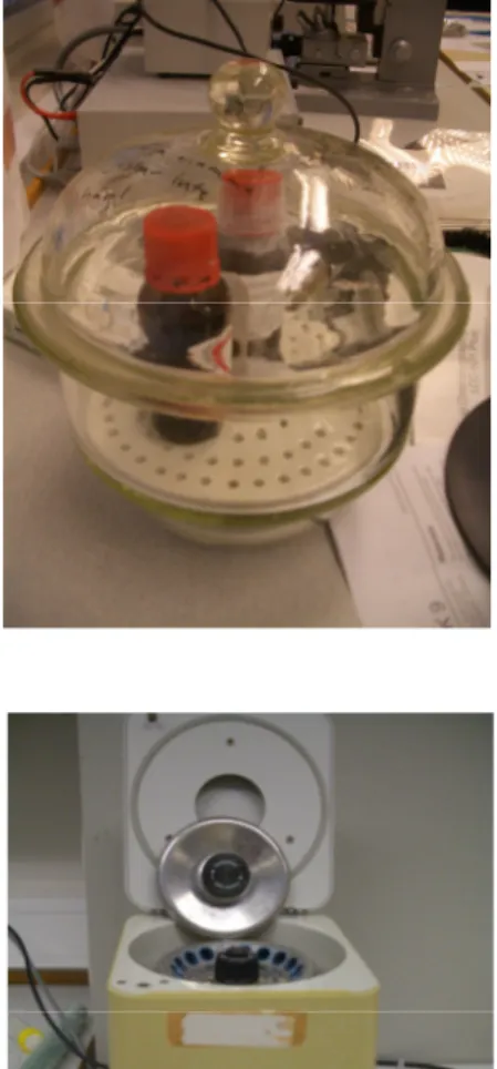
Balance : ( PJ Precisa Junior 60A) Eppendorf Centrifuge :(5415C) Decicator
UltraViolet apparatus
12
2.3 Methods
2.3.1 Optimization:step1: ( Magnet particle marked with FITC)
Different concentrations of FITC were used to mark magnet particles. FITC was diluted 10, 100, 1000, 10000 times using 25mM CO3 buffer, and the resulting surface was microscoped by
using a UV-Filter.
All studied concentrations in combination with NH2 function were fluorescence, and the lowest concentration in combination with COOH function was not fluorescence (see table 3.1, 3.2)
2.3.2 Optimization:step2: (Choice of magnet particle)
Two kinds of magnet particles were selected, sikastar-NH2 function, and sikastar-COOH function (see fig.2.4). Under microscope sikastar-NH2 got marked with FITC fluorescence more officiently than sikastar-COOH. (see table 3.3).
13
2.3.3 Optimization:step3: (Washing magnet particles with different
solvents to remove bounded FITC)
Five different solvents were used to wash the magnet particles and remove the bounded FITC, solvents ( Acetone, 1-butanol, DMSO, 4-propanol, Urea
).
Sikastar-NH2 showed stronger fluoresence than sikastar-COOH after the washing procedure (see table 3.4).2.3.4 Optimization:step4: ( washing magnet particles with detergent to
remove non-specific bindning of FITC)
Magnet particles (sikastar-NH2, sikastar-COOH) were washed with Tween 20 and SDS to remove non-specific binding of FITC. The resulting surface was microscoped with a UV-filter and it showed fluoresence in both functions due to non-specific binding (see table 3.5).
2.3.5 Optimization:step5: (Treatment of magnet particles with
IgG*FITC in constant presence of different solvents)
Sikastar particles were treated with IgG*FITC in constant presence of the following solvents: PBS*10, Pluronic-F127, Tween 20. The resulting surface was microscoped with a UV-filter, Pluronic-F127 showed lower fluoresence than PBS*10 and Tween 20 (see table 3.6).
14
2.3.6 Pegylation of sikastar particles to reduce non-specific binding
PEG-2000 and PEG-3350 are two different kinds of Poly Ethylene Glycol in M.Wt. They are separately linked with sikastar particles to make a long chain around the sikastar particles using EDAC as conjugation substance (see fig. 2.5). The resulting surfaces were treated with IgG*FITC and microscoped with a UV-filter. All showed fluoresence due to non-specific binding of IgG*FITC (see table 3.7).
15
2.3.7 Chemical derivatization: (NVOC of sikastar-NH
2in the Atmos
Bag)
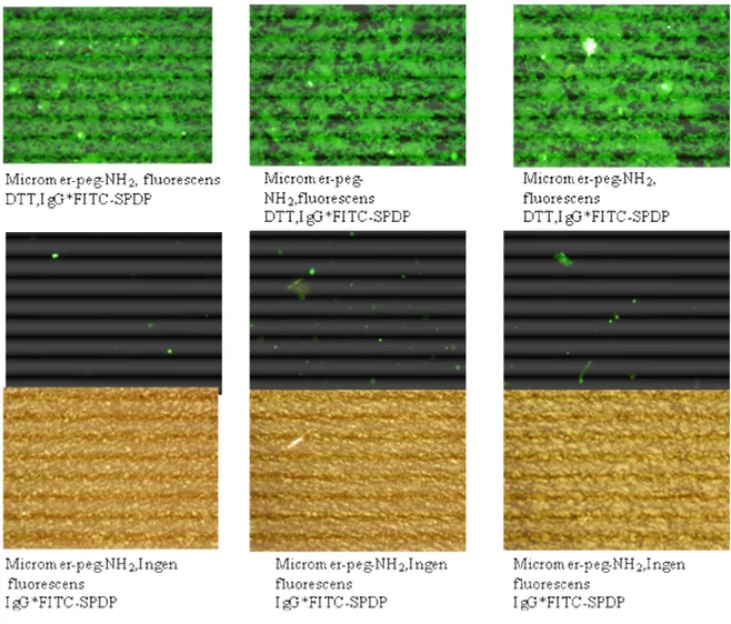
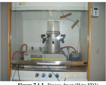
Sikastar-NH2 particles were freeze-dried in a freeze-dryer apparatus (figure 2.6) and used in the N2 environment in the Atmos Bag (figure 2.7). Derivatisation of NVOC was done by using dry DMF and 20% w/v piperidine. NVOC-sikastar-NH2 radiated with UV to remove NVOC, sikastar-NH2 were treated with IgG*FITC using EDAC.
Figure2.6. Freeze-dryer (Heto FD3)
Figure 2.7. Glove Bag (Atmos Bag)
16
2.3.8 Specific bindning of IgG*FITC to micromer particles
Protein thiolation got done by using DTT with SPDP and micromer-PEG-NH2. IgG*FITC was
bound with micromer-PEG-NH2 and it was specific. The result microscoped with UV-filter and
showed fluoresence.
The specific binding can be illustrated by this general reaction:
17
3. Results and discussion
3.1 Optimization:step1: ( Magnet particle marked with FITC)
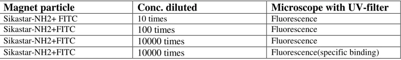
When a different concentrations of FITC was tested to control specific and non-specific binding to sikastar functions, all of the conc. of FITC got binded with sikastar-NH2 and showed fluoresence under microscope with a UV filter (table 3.1). All conc. of FITC got binded with sikastar-COOH and showed fluoresence under microscope except the conc. that got diluted 10000 times (the lowest conc., see table 3.2), here we could see that we had a specific binding to sikastar-NH2 in the lowest concentration.
Table 3.1. list of all the different concentration of sikastar-NH2 marked with FITC.
Magnet particle Conc. diluted Microscope with UV-filter
Sikastar-NH2+ FITC 10 times Fluorescence
Sikastar-NH2+FITC 100 times Fluorescence
Sikastar-NH2+FITC 10000 times Fluorescence
Sikastar-NH2+FITC 10000 times Fluorescence(specific binding)
Table 3.2. list of all the different concentration of sikastar-COOH marked with FITC.
Magnet particle Conc. diluted Microscope with UV-filter
Sikastar-COOH+FITC 10 times Fluorescence
Sikastar-COOH+FITC 100 times Fluorescence
Sikastar-COOH+FITC 10000 times Fluorescence
18
3.2 Optimization:step2: (Choice of magnet particle)
The difference between sikastar-COOH and sikastar-NH2 herewas that sikastar-NH2 showed
more fluoresence than sikastar-COOH under microscope with a UV-filter (table 3.3), and it means that we had a specific binding with sikastar-NH2.
Table 3.3. Magnet particles tested under microscope with UV-filter.
Magnet particle Microscope with UV-filter
Sikastar-NH2 High Fluoresence (specific binding)
Sikastar-COOH Low Fluoresence
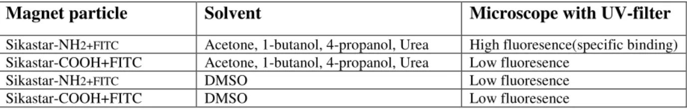
3.3 Optimization:step3: (Washing magnet particles with different
solvents to remove bounded FITC)
Solvents (Acetone, 1-butanol, DMSO, 4-propanol, Urea) was used to wash sikastar particles and remove bounded FITC. For solvents (Acetone, 1-butanol, 4-propanol, Urea
)
sikastar-NH2showed stronger fluoresence than sikastar-COOH after the washing procedure, which means that there was a specific binding between sikastar-NH2 and FITC and it was more difficult to
remove bounded FITC from sikastar-NH2. For DMSO, sikastar-NH2 and sikastar-COOH
showed lower fluoresence, which means that we could remove bounded FITC from sikastar particles by using DMSO(see table 3.4).
Table 3.4. Washed magnet particles with different solvents to show which solvents that can be
used to remove bounded FITC.
Magnet particle Solvent Microscope with UV-filter
Sikastar-NH2+FITC Acetone, 1-butanol, 4-propanol, Urea High fluoresence(specific binding) Sikastar-COOH+FITC Acetone, 1-butanol, 4-propanol, Urea Low fluoresence
Sikastar-NH2+FITC DMSO Low fluoresence
19
3.4 Optimization:step4: ( washing magnet particles with detergent to
remove non-specific binding of FITC)
When magnet particles (sikastar-NH2, sikastar-COOH) were washed with Tween 20 and SDS to remove non-specific binding of FITC, and the result was microscoped with UV-filter, it showed fluoresence in both functions due to non-specific binding (table 3.5).
Table 3.5. Washing magnet particles bounded with FITC by detergent
.
Magnet particles Solvent Microscope with UV-filter
Sikastar-NH2+FITC Tween 20, SDS Fluoresence(non-specific binding)
Sikastar-COOH+FITC Tween 20, SDS Fluoresence(non-specific binding)
3.5 Optimization:step5: (Treatment of magnet particles with
IgG*FITC in constant presence of different solvents)
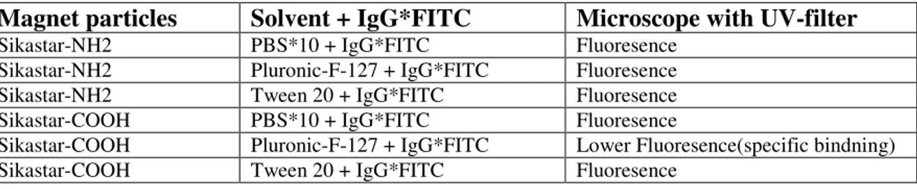
Sikastar particles were treated with IgG*FITC in constant presence of solvents PBS*10, F127 and Tween 20. When the result was microscoped with a UV-filter, Pluronic-F127 showed lower flouresence than PBS*10 and Tween 20, which means that there was a specific binding between sikastar particles and IgG*FITC in a presence of pluronic-F127 (see table 3.6)
Table 3.6. Treatment of magnet particles with IgG*FITC in constant presence of different
solvents.
Magnet particles Solvent + IgG*FITC Microscope with UV-filter
Sikastar-NH2 PBS*10 + IgG*FITC Fluoresence
Sikastar-NH2 Pluronic-F-127 + IgG*FITC Fluoresence
Sikastar-NH2 Tween 20 + IgG*FITC Fluoresence
Sikastar-COOH PBS*10 + IgG*FITC Fluoresence
Sikastar-COOH Pluronic-F-127 + IgG*FITC Lower Fluoresence(specific bindning)
20
3.6
Pegylation
of sikastar particles to reduce non-specific binding
PEG-2000 and PEG-3350 were used here to link with sikastar particles to make a long chain around the sikastar particles using EDAC as a conjugation substance. They then got treated by IgG*FITC, and the result was microscoped with a UV-filter. All showed fluoresence due to non-specific binding of IgG*FITC (see table 3.7).
Table 3.7. Pegylation of sikastar particles with different kind of PEG, and treatment with
IgG*FITC
Magnet particles PEG IgG*FITC Microscope with UV-filter
Sikastar-NH2 PEG-2000 + IgG*FITC Fluoresence (non-specific bindning)
Sikastar-NH2 PEG3350 + IgG*FITC Fluoresence (non-specific bindning)
Sikastar-COOH PEG-2000 + IgG*FITC Fluoresence (non-specific bindning)
21
3.7 Chemical derivatization: (NVOC of sikastar-NH
2in the Atmos
Bag)
NVOC is a very sensitive protein towards light and water. Therefore it is used in the Atmos Bag that is protected from water, air and any unnecessary light sources (see figure 2.6). The derivatisation of NVOC got done in an N2 environment, NVOC-sikastar-NH2 got radiated with
UV to remove NVOC, and sikastar-NH2 was treated with IgG*FITC using EDAC as a
conjugating substance.
NVOC and sikastar-NH2reaction:
Sikastar-NH2 → sikastar-NH-NVOC ---- UV →
Sikastar-NH2--- IgG*FITC + EDAC →
Sikastar-NH-IgG*FITC
Sikastar-NH-NVOC…….Ingen UV ………..→
22
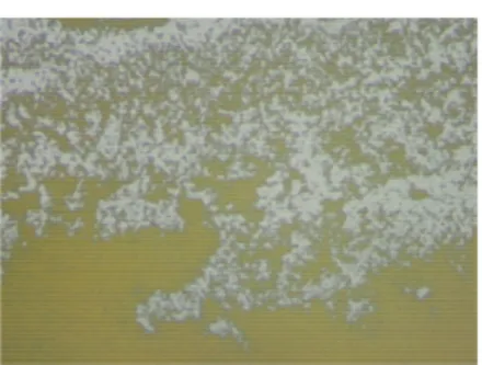
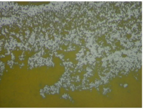
3.8 Specific bindning of IgG*FITC to micromer particles
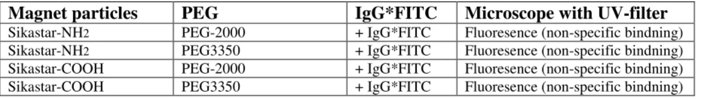
The thiolation method was used in this experiment. Protein thiolation was made by DTT using SPDP and micromer-PEG-NH2. IgG*FITC was bonded with micromer-PEG-NH2
specific. The resulting surface was microscoped with UV-filter and showed fluoresence. The test was controlled and showed no fluoresence without DTT (figure 3.1).
Figure 3.1. Microscope pictures for specific bindning of IgG*FITC to micromer particles using
23
4. Acknowledgements
I would like to acknowledge the following people for their invaluable help with the work in this project.
First of all I would like to thank my supervisors Sven Oscarsson for helping me with this project. I would also like to thank PhD-student Greger Ledung for guiding me in this project and for a great scientific exchange. Thanks are also due to PhD-student Lars-Erik Johansson for helpfully discussing with me during my job in the lab. Further on I would like to thank assistant Markus Pitkinnen for his availability at any time when I was in need of guidance in the lab, and for making the working atmosphere at the lab a very pleasant one. I also want to thank Jamal Saywan for fixing any technical problems that appeared.
I will never forget Dalila Caratas for her support throughout my presence in Biochemistry Institution and quickly fixing any administrational problems that appeared .
I want to thank all colleagues for supporting me during my work at IBK.
I thank my husband and my two sons for constantly supporting me during my study at the university. I will only say Thank You All.
24
5. Abbreviations
FITC Fluorescein-5- Iso ThioCyanate NVOC 6-NitroVeratrylOxyCarbonyl SDS Sodium Dodecyl Sulfate DMF N,N-Dimethylformamide DMSO Dimethyl Sulfoxide UREA Diaminomethanal
MOPS 3-(N-Morpholino)PropaneSulfonic acid
Tween 20 PolyOxyEthylene Sorbitan Monolaurate(Polysorbate 20)
EDAC N-(3-Dimethylaminopropyl)-(N-ethyl-carbodiimide hydrochloride) IgG Immuglobulin Antibody
IgG-FITC Immuglobulin Antibody bounded with Flouresence-5-Iso Thio Cyanate SPDP N-Succinimidyl 3-(2-Pyridyldithio)Propionate
Pluronic F-127 Polyethylene Polypropylene Glycol
M Molar Concentration,ie.6.022*1023¨molecules per litre of solvent MW Molar Weight (1 g/6.022*1023 molecules=1Da)
PBS Phosphate Buffered Saline PEG Poly (Ethylene)Glycol PEGylation Areacoverage with PEG
UV UltraViolet light wavelength range HMPA Hexa Methyl Phosphore Amide DNA DeoxyriboNucleic Acid
Sikastar-groups Sikastar-NH2 +Sikastar-COOH
Sikastar-M Magnetic silica particles Micromer-M Magnetic latex particles
Sikastar-NH2 Magnetic silica particles bounded with amide function
Sikastar-COOH Magnetic silica particles bounded with carboxyl function
Micromer-peg-NH2 Pegylated magnetic latex particles bounded with amide function
µl Microliter mM Millimolar gr Gram V Volume W Weight Con. Concentration m Mass ml Milliliter n Mole number mg Milligram
EDTA Ethylenediaminetetraacetic acid DTT Dithiothreitol
NMR Nuclear Magnetic Resonance N2 Nitrogen gas NH2 Amide COOH Carboxyl HCL Hydrogen cloride CO3 Carbonate min. Minute
25 temp. Temperature
fig. Figure
PEG 2000 0,0-Bis(2-aminoethyl)Polyethylene Glycol PEG 3350 Polyethylene Bis(amine)
Tween 20 Polysorbate -N=C=S Isothiocyanate Na+ Sodium ion K+ Calcium ion Na-acetate Sodium acetate nm Nanometer
TPP Techno Plastic Products pKa Acid Dissociation Constant pH Power of hydrogen
26
6. Reference list
1.http://www.davidson.edu/academic/biology/courses/Molbio/SDSPAGE/SDSPAGE.ht...200 60215
2.Carlsson, J., Drevin, H.and axen, R.(1978). ”Protein thiolation and reversible protein-protein conjugation.N-succinimidyl-3-(2-pyridyl dithio)Propionate, anew heterobifunctional reagent”. Biochem.J.173, 723-737. 3. http://www.sigmaaldrich.com...product nr.Z118370 4. http://www.biotium.com/prodindex...pluronic F-127...2006-03-01 5. http://www.sigmaaldrich.com/catalog/search/productDetail....MOPS...2006-03-03 6.http://www.sigmaaldrich.com/catalog/search/productDetail... FITC...2006-05-18 7. http://www.drmr.com/abcon/FITC.html...2006-02-22 8. http://www.answers.com/topic/detergent...2006-02-15
9. CALBIOCHEM, ”A Guide to the properties and Uses of Detergents in Biology and Biochemistry”. By Judith Neugebauer…Doc.No.CB0068-0892
10. http://www.mcb.uct.ac.za/sdspage.html...2006-05-19
11. http://en.wikipedia.org/wiki/MOPS...2006-05-11
12. http://www.sigmaaldrich.com...mops...2006-05-19
13. http://en.wikipedia.org/wiki/Dimethyl_sulfoxide..2006-05-22
14. Greg T. Hermanson ”Bioconjugate Techniques”. ISBN 0-12-342336-8….2006-05-24
15. www.micromod.de Product Descriptions Vertion 0.6 generated 2006-05-24 13.25 for 193.11.81.16 …sikastar-M, micromer-M
16. J. Chem. Soc., perkin Trans. 1, 2002, 125-142
17. Uptima FT-UP79042 , SPDP,Ic-SPDP, Sulfo-Ic-SPDP, Heterobifunctional cross-linkers
27
7. Appendex
7.1 Instruments used in library
Figure 7.1.1. Fluoresence microscope (Nikon,ECLIPSE,E600)
28
Figure 7.1.3. Freeze-dryer (Heto FD3)
29
Figure 7.1.5. Decicator
Figure 7.1.6. Eppendorf Centrifuge(5415C)
30
31
7.2
Microscope pictures
Sikastar-COOH(10*/0,25) Sikastar-COOH (40*/0,75) IgG-FITC(10*/0,25)(with UV)32 Sikastar-NH2 (10*/0,25) Sikastar-NH2 (40*/0,75) Micromer-NH2 (10*/0,25) Micromer-NH2 (40*/0,75)
33
Micromer peg-NH2 (10*/0,025)
Micromer peg-NH2(40*/0,075)
IgG-FITC(without UV)
Figure 7.2.3. Microscope pictures for micromer peg-NH2 & IgG-FITC
34
7.3 Derivatization of one half of a sphere
NH2 NH 2 NH 2 NH 2 NH 2 NH 2 NH 2 NH 2 NH 2 NH2 NH NH NH NH NH NH NH NH NH NH X X X X X X X X X X NH2 NH 2 NH 2 NH NH NH NH NH NH 2 NH2 X X X X X NH2 NH 2 NH 2 NH NH NH NH NH NH 2 NH2 X X X X X NH NH NH NH NH NH NH NH NH NH X X X X X
A
B
C
D
E
35
7.4 Treatment of magnet particles with IgG*FITC in constant presence
of different solvents
Sikastar-COOH(50µl) → Washed with PBS*10(3*250µl) + (IgG*FITC) → Sikastar-COOH(Fluoresence).
Sikastar-NH2(50µl) → Washed with PBS*10(3*250µl) + (IgG*FITC) → Sikastar-NH2(Fluoresence).
Sikastar-COOH(50µl) → Washed with Pluronic-F127 ( PBS used as a solution) (3*250µl) + (IgG*FITC) → Sikastar-COOH (Lower Fluoresence).
Sikastar-NH2(50µl) → Washed with Pluronic-F127 ( PBS used as a solution) (3*250µl) + (IgG*FITC) → Sikastar-NH2(Fluoresence).
Sikastar-COOH(50µl) → Washed with Tween 20 (PBS used as a solution) (3*250µl) + (IgG*FITC) → Sikastar-COOH(Fluoresence).
Sikastar-NH2(50µl) → Washed with Tween 20 (PBS used as a solution) (3*250µl) + (IgG*FITC) → Sikastar NH2(Fluoresence).
36
7.5 Specific binding of IgG*FITC to micromer particles
N O O O S O S N N N Micromer-peg-NH2 PEG N S S PEG NH2 SPDP PEG N H SH HS OH OH SH O DTT FITC FITC NH S S O CH2 CL NO2 CH3O OCH3 6-Nitroveratrylcloride OCH3 NO2 CH2 S O N H PEG PEG N O SH H 340-400 nm PEG N H O S S N H FITC Specific bindning av IgG*FITC till Micromer-peg-NH2
O H O IgG*FITC UV OCH3 * * *
37
7.6 FITC conjugation with antibody
O
O
O O
FITC conjugation with antibody
N C S O OH HO
+
N H C N S H R O OH HOFluorescin iso thiocyanate (FITC) Antibody (IgG)