http://www.diva-portal.org
Postprint
This is the accepted version of a paper published in Wear. This paper has been peer-reviewed but does not include the final publisher proof-corrections or journal pagination.
Citation for the original published paper (version of record): Ghasemi, R., Elmquist, L. (2014)
A study on graphite extrusion phenomenon under the sliding wear response of cast iron using microindentation and microscratch techniques.
Wear, 320(1-2): 120-126
http://dx.doi.org/10.1016/j.wear.2014.09.002
Access to the published version may require subscription. N.B. When citing this work, cite the original published paper.
Permanent link to this version:
Author's Accepted Manuscript
A study on graphite extrusion phenomenon under the sliding wear response of cast iron using microindentation and microscratch techniques
Rohollah Ghasemi, Lennart Elmquist
PII: S0043-1648(14)00279-8
DOI: http://dx.doi.org/10.1016/j.wear.2014.09.002 Reference: WEA101103
To appear in: Wear
Received date: 4 May 2014
Revised date: 2 September 2014 Accepted date: 3 September 2014
Cite this article as: Rohollah Ghasemi, Lennart Elmquist, A study on graphite extrusion phenomenon under the sliding wear response of cast iron using microindentation and microscratch techniques,Wear,http://dx.doi.org/10.1016/j. wear.2014.09.002
This is a PDF file of an unedited manuscript that has been accepted for publication. As a service to our customers we are providing this early version of the manuscript. The manuscript will undergo copyediting, typesetting, and review of the resulting galley proof before it is published in its final citable form. Please note that during the production process errors may be discovered which could affect the content, and all legal disclaimers that apply to the journal pertain.
A study on graphite extrusion phenomenon under the sliding wear
response of cast iron using microindentation and microscratch
techniques
Rohollah Ghasemi
a,Ö, Lennart Elmquist
a, ba Department of Mechanical Engineering, Materials and Manufacturing - Casting,
School of Engineering, Jönköping University, PO Box 1026, SE-551 11 Jönköping, Sweden
b SinterCast AB, Technical Centre, Kungsgatan 2, SE-641 30 Katrineholm, Sweden
ÖCorresponding author: Tel: +46 36101179; fax: +46 36166560
E-mail address: rohollah.ghasemi@jth.hj.se
Abstract
This study focuses on the graphite flakes extrusion mechanism during microindenting and microscratching of cast iron. Observations on the graphite response under abrasive conditions revealed that the matrix deformation which is occurred during a sliding wear condition could have a significant influence on its lubricating performance. Simple microindentation and microscratch tests were conducted to explore the lamellar graphite contribution to tribofilm formation under abrasive wear conditions. The results obtained showed that induced plastic deformation which developed adjacent to the graphite compressed the lamellas and in turn resulting in extrusion of the graphite from its natural position. Further investigations on both indentation and scratch tests indicated that, surprisingly, the graphite began to be fractured and extruded from the centre of graphite lamellas, irrespective of the lamella size. Additionally, a mechanism was proposed to explain the self-lubricating and the extrusion behaviour of the lamellar graphite as a result of indentation.
Keywords: Lamellar graphite iron; Graphite extrusion; Sliding wear; Abrasive wear; Microindentation testing; Microscratch testing
1 Introduction
Generally speaking, cast iron can be considered to be a self-lubricating metal-base composite material [1]. Hence, traditionally lamellar graphite iron has been used in variant tribological applications, especially, in situations where encountering the sliding motion such as disc brakes and clutch systems [2, 3]. The other application where excellent tribological performance is of great importance is piston ring-cylinder liner system. Improvements in the tribological behaviour of cast iron are primarily attributed to factors such as microstructure and graphite morphology. Prasad [4]
investigated the effect of microstructures in terms of the amount of ferrite, pearlite, and graphite on wear characteristics. He also performed more studies of the influence of graphite characteristic on wear properties in terms of morphology (lamellar and spheroidal), size, content, and distribution on sliding wear surfaces. Furthermore, he indicated that lamellar cast iron (predominately that with a pearlitic matrix) offers significantly better wear resistance in both dry and oil-lubricated conditions than spheroidal graphite iron. Based on the investigations into the wear properties of cast iron performed by Sudarshan [5] and Taylor [6], a pearlitic A type lamellar graphite iron, with a limited quantity of ferrite, is a viable candidate for piston ring applications. Additionally, regarding the influence of hard phases on wear improvement, Eyre [3] and Nadel [7] performed valuable
investigations, the conclusions of which were validated by other researchers [5, 8]. They stated that hard phases stand out from the matrix on a fully run-in surface, and thereby improve the wear resistance by minimizing the direct metal to metal contact during sliding.
Regarding the effective lubricating nature of the graphite in lamellar iron, Sugishita et al., in two separate works [1, 9], examined the effect of tribofilm formation under the reciprocating sliding and rolling-sliding conditions, respectively. In both studies, the friction and wear performance of lamellar cast iron were influenced by the surface graphite conditions. So that for conditions in which the graphite can easily lubricate the sliding surfaces a significant decrease, by several orders of magnitude, was observed both in coefficient of friction and wear rate. The good tribological properties of graphite is basically associated with its anisotropic structure and its weak interlayer van der Waals forces [10], as well as the fact that it provides a large lubricating surface area in the lubricant mixture during sliding. The interactions between these weak interlayers cause smearing processes and the formation of a very thin lubricating film between the sliding surfaces [10]. However, and despite this important function, the self-lubricating mechanism of lamellar iron remains ambiguous and has not been demonstrated and fully explained in scholarly literature. During sliding, the ease with which a graphite particle can be extruded from its embedded position is directly proportional to the improvement in tribological performance [11]. In previous work [12], Ghasemi et al. found that under sliding conditions, not all graphite lamellas serve the same graphite supplying function. Some lamellas are partially or entirely covered after a given period of operational time, while others remain uncovered and lubricate the sliding surfaces. Thus, this covering tendency is of critical importance, as the consequence of a less effective smearing propensity is an increased risk of incidences of scuffing or other issues associated with poor tribological properties. In the same study, the relationship between lamellar graphite orientation and covering tendency during sliding was investigated; this demonstrated that graphite lamellas
that are parallel or close to the sliding direction are more easily covered than those oriented away from the sliding direction. However, the metal matrix deformation and consequent effect on the graphite as a result of sliding remain ambiguous.
The abrasive wear behaviour of lamellar irons has been studied, using scratch testing techniques, by Mendas et al. [13]. They investigated the effect of microstructure, applied various loads and attack angles of conical indenter on coefficient of friction and wear characteristics. According to the results obtained, graphite plays an important role in affecting the wear performance of the
specimens. Additionally, Nakamura et al. [14], in examining lamellar iron abrasion patterns, demonstrated that sliding surfaces which are in contact only interact within a micro localized area. They further demonstrated that the graphite film that is formed on the micro scale is identical to that on the macro-scale. Consequently, it derives the attentions for those who attempt to conduct further research into the nature of graphite film formation and its corresponding mechanisms to do so on the micro, rather than macro scale. A single micro contact, when subjected to a typical abrasive particle, can cause the macroscopic contact, and so the interaction of a single hard particle can be used to study and explain the macroscopic wear characteristics of a used lamellar iron component.
Any circumstance which results in or exacerbates a scratch on the matrix, particularly in the vicinity of the lamellar graphite, can cause major elastic and plastic deformation in the matrix during
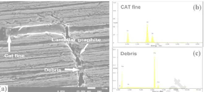
sliding. This can be seen in Fig. 1(a) which corresponds to a real worn surface achieved after 16,000 h operates as marine diesel engine piston ring. As known, the hard abrasive particles present in the piston ring-cylinder liner sliding system are originated either from the fuel catalyst (CAT) fines [15] or produced as the consequence of adhesive or corrosive wear (i.e. oxides/debris) [16] which were analysed by EDS technique and shown in Fig. 1(b) and (c), respectively. CAT fines are considered to be impurities which are present in heavy fuel oil, and result from catalytic
cracking during the oil refining process. Hard aluminium silicate particles in various forms, sizes, and hardness ranges are used during the catalytic cracking process [15]. This interaction between the hard particles, matrix, and graphite should be thoroughly taken into consideration in a situation where a continuous supplying of graphite is required. According to Jones et al. [17], a moderate to high concentration of these hard particles may significantly impact on the wear behaviour of the sliding surfaces, in turn resulting in excessive wear to fuel pumps, cylinder liners, and piston rings. From this viewpoint, a single asperity or piece of debris may either indent a mating elastic surface, or become flattened during sliding [18].
Fig. 1. SE graphite, The pres lamellas. explore th lubricate
2 Exp
2.1
M
Two pear diesel en composit Table 1. C C S 3.30 12.2
M
To exam metallogr down to a were stud specimen to study t EM image in along with c ent study inv Microindent he matrix an sliding surfaperimental
Materials
rlitic lamellar gine running tion of the te Chemical co Si Mn .55 0.85Microstruct
ine the micro raphically us a 3 μm finish died using o n. The scann the deformat ndicating the correspondin vestigates th tation and m nd lamellar g aces when it
l procedu
r graphite iro g with heavy ested materia omposition o Ni Mo 0.35 0.60tural analys
ostructure, t sing diamond h. A 2% Nita ptical micros ning electron tion pattern e presence o ng EDS spe he interactio microscratch graphite resp t is subjectedre
on piston rin y fuel oil, we als. of the lamella Cu Ti 0.85 0.07sis
he specimen d paste, follo al solution wa scopy. Fig. 2 n microscopy of the micro of a CAT fine ctra. ns between testing were ponse, as we d to abrasive g segments re used in th ar iron tested Cr V 7 0.15 0. ns were grou owing a stan as used for e 2 shows the y (SEM) in s ostructure aft e and wear d the hard ab e carried out ell as the wa e particles. , which were he study. Ta d samples (w S P 15 0.08 0und and the ndard sample etching. The microstructu secondary e ter microinde debris entrap brasive partic t in order to ays in which e sectioned f ble 1 presen wt.%). P Fe 0.10 Bal. n polished e preparatio e etched mic ure of the et lectron (SE) entation, and pped in the la
cles and gra understand graphite ma from a marin nts the chem on procedure crostructures tched cast iro ) mode was d microscrat amellar phite and ay act to ne mical e s on used tch
tests. In a chemical Fig. 2. Op the matrix
2.3
M
The micro deformat The inde with apex pearlitic m 15 s. In a locations indentatio g on a dia2.4
M
To simula the abras test was only simu during sli employed the result actual pa addition, ene composition ptical photom x is pearliteMicroindent
oindentation ion in the ca nter used wa x semi-angle matrix and th addition to th on the cast ons made cl amond polisMicroscratc
ate elementa sive particles conducted. T ulates the cirding. The sa d for the mic ts achieved article loadin ergy dispers n of the cons micrograph i (2% Nital so
tation test
n test was pe ast iron matras based on es of 136⁰. In he hard phas he hardness iron matrix, ose to the g shed surface
ch testing
ary abrasive s to the self-The test was rcumstances ame indente croscratch te under apply g on real sys sive X-ray sp stituents wh illustrating h olution).ing
erformed on ix. The defo n a Vickers m n addition, th ses was me measureme and deform raphite lame e for a dwell e wear of the -lubricating b s performed s in which a er as was use est. Various ying a load o stem. In bot pectroscopy ich caused t ard phases 10 mm thick rmation was microhardne he microhard asured by a ent, several mation charac ellas. The ap time of 15 s e lamellar ca behaviour of under a con single hard ed for the m range of loa f 200 g is pr h microinde (EDS) was e the abrasion in a lamellar k specimens s induced clo ss test, with dness value pplying a loa indentations cteristics we pplied test lo . st iron and e f the graphite nstant load. particle mov microhardnes ads could be resented so ntation and employed to n. r cast iron;th s in order to ose to the gr a typical dia correspond ad of 200 g s were made ere compare oad for indenexamine the e lamellas a
The presen ves over the ss measurem selected, ho that this is re microscratch o study the he remainde make plasti raphite lame amond pyram ding to the
and dwell tim e at different d with ntations was contribution microscratc t investigatio cast iron m ment was owever here epresentativ h tests, the er of c ellas. mid me of s 500 n of ch on atrix e only ve of
distance between the indentations/scratches was carefully controlled, being maintained at three times the length of the indentation diagonal, so that the stress field effect in the vicinity of the indentations/scratches was eliminated. All indentations and scratches were made under ambient laboratory conditions.
3 Results and discussion
3.1
Microstructure of the polished lamellar cast iron surface
As shown in Fig. 2, the lamellar cast iron microstructure has three distinct constituents. The matrix is mostly pearlite (a fine mixture of ferrite and cementite), with a very limited quantity of free ferrite. Randomly oriented and distributed graphite lamellas, varying in thickness and length, are also observed in the microstructure. Moreover, there exist some hard phases, which are revealed as white areas and dispersed throughout the matrix. As stated above, the improvement in wear resistance of the piston rings and cylinder liners is somehow related to the amount of these hard particles, which minimize the direct metal to metal contact [3, 5, 7, 8].
Table 2 presents the average microhardness of the pearlite and white hard phase. In order to ascertain the repeatability of the measurements, the average of six indentations was calculated. The average microhardness of the hard phase present in the structure was 753 HV which, in comparison with the microhardness of pearlite (292 HV), increases the overall hardness of the cast iron. The effect of the hard phase on wear resistance will be further explored in section 3.3. However, one should consider that the data presented for pearlite microhardness does not take into account the pearlite lamellar orientation and coarseness of the pearlite, which may have caused a differing hardness value for a given coarseness and lamellar pearlite orientation. Table 2. Vickers microindentation hardness results for the constituents of the lamellar cast iron samples investigated.
Constituent Length of diagonal [mm]±SD Vickers microhardness HV0.2 [kg/mm2]±SD
Pearlite 0.0357±0.0017 292.25±26.72
Hard phase 0.0225±0.0025 752.58±166.56
3.2 Microindentation
testing
Given the above observations, it was considered to be of value to study in detail the mechanism behind the self-lubricating process of the graphite, and its contribution to the formation of the tribofilm. Consequently, the microindentation test, together with a microscopic analysis, was performed. Indentation leaves a permanent impression on the material surface, and induces both compression stresses and shear stresses on the four-sided slant impression surfaces. This
is believe mechanis serve to s sliding pa 3.2.1 La Fig. 3(a) prior to in the lamel indentatio Fig. 3. (a showing as a resu When co imaging o compress compress The net f plastic de plastically region. T compress displacem on alumin ed to facilitat sms, particu simulate the arts, albeit to amellar gra presents a c ndentation. T llar graphite on at 500 g i ) Optical mic the same ar ult of indenta mparing the of the surfac sed and extr sive stress w force applied eformation o y deformed he present i sed (due to ment of the g nium alloy-g te a better u larly those w e deformation o an extreme aphite’s resp cross-sectio This being do through def is shown in crograph of rea at a high ation. e graphite fea ce response ruded from i which is gen d to the grap of the matrix. area, visible nvestigation elastic/plast graphite. Fur raphite parti nderstanding which occur n caused by ely exaggera ponse when n of a typica one near to formation of Fig. 3(b) at a the lamellar her magnifica ature prior to of the cast i ts original po erated as a phite during i . However, fo e as an impre n revealed th ic strain) in t rthermore, a icle compos g and interp close to the y an abrasive ated degree. n subjected al graphite in the graphite the metallic a higher mag graphite be ation, in orde o indentation iron indicatin ocket during result of ind indentation w ollowing the ession on th hat the graph
the planes d according to ite, and Sarm
pretation of th graphite lam e particle tra . d to microin n a lamellar c e caused stre matrix. The gnification. efore indenta er to further n, the SEM m ng that the la g loading due entation. was a direct relief of the e surface, re hite lamellas during indent the studies madi et al. [1 he related de mella. Moreo avelling along ndentation t cast iron pol ess to be tra e close-up vie ation; (b) SEM illustrate ext micrograph a amellar grap e to the indu result of bo e applied forc emained on s were suffic tation to pre performed b 19] on coppe eformation over, it could g the actual testing ished surfac ansferred tow ew of the M image truded graph allows clear phite was uced th the elastic ce, only the
the affected iently cipitate the i by Liu et al. [ er–graphite d ce, wards hite c and d initial [11]
composit film forma In anothe indicated appeared marked a into two h Fig. 4. On perfectly and in tur planes. T tendency extrusion Fig. 4. Th In additio matrix-gr and the n suggestiv deformat line), as s Therefore graphite w tes, subsurfa ation on tribo er example s an extrusio d in the cent area by the b halves, indic ne explanati straight, and rn stress dis This latter ob y towards a s n pattern whi he extrusion on, two distin raphite interf near-untouch ve of the fac ion of the m seen in Fig. e, this simple when subjec ace deforma osurfaces. shown in Fig n relationsh re of the lam black circle n cated by two ion for this p d instead tak stribution, aro bservation im specific relat ich is repres mechanism nct regions m face, and a s hed region o ct that, during atrix in the a 3(b) and Fig e experimen cted to shea ation during s g. 4, which is ip between t mellar graphi near the edg white arrow phenomenon kes a shape ound the lam mmediately r tionship betw sented here. m of the lame may be ident sharp, clean of the graphit g indentation area around g. 4, rather th nt enables di ar stress. sliding plays s similar to th the lamellar ite, which ca ge of the gra ws, with diffe n could be re rather like a mellar graph raises the qu
ween the lam
ellar graphite tified after in , and shiny e te as shown n, the extrus the lamellar han at the m iscussion re s an importan he earlier illu graphite an an be confirm phite shown ring orientat elated to the a twisted pla ite caused to uestion as to mellar graph e caused by ndentation; th edge betwee n in Fig. 4. Th sion is largely r graphite (p metal matrix-garding the nt role in gra ustration, ob d indentatio med by an ex n in Fig. 4. T tions is also fact that the ate, meaning o extrude it i o whether the ite structure microindent he unaffecte en the displa his individua y governed redominatel lamellar gra natural beha aphite lubrica servations n. The crack xamination o he bifurcatio clearly seen e lamella is n g that indenta in two differe ere exists an e and the tation. ed area near aced graphit al characteris by the y near to the phite bound aviour of lam ating ks of the on n in not ation, ent ny r the te stic is e end ary. mellar
One poss bonding w compared this regio and othe literature heteroge sulphides interfaces incoheren ultimately Fig. 5. Th whilst the On the ot graphite cast iron and extru the prese test was surprising The fract similar in sible explana which exists d to the una on can presu r phases suc , and with re neously on c s (MnS) [25, s between th nt bonds bec y lead to lam he response ey vary in siz ther hand, n interface, wh matrix and g uded from th ent observat conducted f gly, this was ure correspo dentation co
ation for suc s within the g ffected grap umably, how ch as defect egard to the complex silic 26], this allo he substrate comes more mination of th of two grap ze, both disp
o evidence f hich could b graphite con he centre, rat ion and asce for plenty of s apparently ondence of t onditions is s ch an observ graphite laye phite-matrix i ever, be rela ts and imper point that th cates, oxide ows the form e and the gra e likely [27]. he graphite l
phite lamellas play the sam
for graphite e the proof o nstituent so t
ther than tha ertain wheth lamellas of a the most co two lamellas shown in Fig ved interactio ers, particula nterface. Th ated to the w rfections in g he lamellar g s [20-22], in mation of coh aphite [20]; i Such condit amellas. s to the simi me extrusion delaminatio of the existe that is much at of graphite her this tende approximate ommonly obs s, which vari g. 5. As Fig.
on may be re arly at, or clo he appearan weaker bond general. As h raphite nucl termetallic c herent/semi-.e. the prese tions provoke lar microind mechanism n was detec ence of far st easier for th e-matrix inte ency was do ely the same
served patte ed in length 5(a) demons
elated to the ose to, the ce nce of the sh ds between g
has been dis eation begin compounds [ -coherent low ence of som e the shear entation, ma . cted in the m tronger bond he graphite t erface. In ord ominant, the e size; howev erns in all cas but were su strated in lam e nature of th entre, when eared graph graphite lam scussed in ns [23, 24] and w energy e weak stress, and ade nearby; metal matrix-ds between t to be fractur der to genera microindent ver, and rath ses. ubjected to th mellas with he hite in mellas may the red alize tation her he
larger siz lamella, t Fig. 6. SE In both ca tendency identical the tested interactio surface d between pockets, Fig. 6. 3.2.2 C Various i indentatio indentatio markedly 7(a) show by the tw graphite. away from was extru Nomarsk ze, the 500 g the same loa
EM image of ases, the sim y from the ce to situation i d environme on with abras damage, in th the scratche and coverin haracteriza ndentation s on response on shape for y different ind ws two perfe wo microinde These inde m the lamell uded as a re ki microscopy g applied loa ad was suffic f the worn su milar behavio entre. Compa in real piston ent, however sive particles he form of s es [12] and g g the lamella ation of mic shapes were e of the pear r different gr dentation res ectly square ntations whi ntation shap as. Howeve esult of the d y technique ad affected o cient to sign urface of a m our was obs ared to reali n ring during r it could give s [28]. Fig. 6 cratches fro graphite flak as due to ma roindentatio e examined a rlitic lamellar raphite lame sponses. Th and clear in ich were ma pes are very
r, Fig. 7(b) i damage (frac was used to only some pa ificantly imp marine diese served, with ty, this extre g sliding in te e valuable in 6 shows a re m hard part kes including atrix deform on shapes and classifie r iron under d
llas, and Fig he applied lo dentations s ade, despite similar to th llustrates a d cture and/or o further incr arts of a lam act the whol
el engine, op the graphite eme situation erms of appl
nformation o eal worn pisto
icles, is clea g the extracti ation, are po ed by Young discussion r g. 7 shows tw oad was 500 so that the g them being hose made in different situ deformation rease contra mella while, fo le graphite ( perated for 1 e displaying a n might not b ied load, pa on the way o on ring surfa arly visible. T ion of the gr ointed out by and Millman evealed a cl wo graphite g in both in raphite was made very c n matrix, but uation, in wh n) caused by ast and show
or a smaller see Fig. 5(b 6,000 h. an extrusion be exactly rticle size an of the graphit ace, wherein The interactio raphite from y white arrow n [29]. The lear differen lamellas wit stances. Fig not influenc close to the t are further ich the grap y indenting. T w the area b)). n nd te n the on their ws in ce in th g. ced hite The
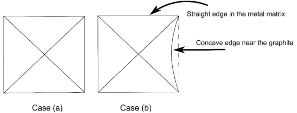
deformed graphite where no present r of the ma most like Mendas [ phases, s Fig. 7. (a to the gra 3.2.3 T The most depicted Fig. 8(a). the graph d as a result became con o interaction response cou atrix; therefo ly associate [13], the cha such as carb ) SEM photo aphite lamell he propose t uniquely sh in Fig. 8. In They typica hite lamellas of indentatio ncave. They was detecte uld closely c re, it is reas d with the la ange in inden bides, close omicrograph las as (a) un ed mechanis haped inden most cases ally were ass s, or close to on. It may be were affecte ed with the g correspond t onable to co amellar grap ntation shap to the inden h and optical naffected; (b sm for grap ntations obse , a near-perf sociated with o the graphite e observed ed to a much graphite, whi to a small pla onclude that hite extrusio pe could also ntation area. l image, sho ) extruded, r phite extrus erved during fectly square h indentation e but withou
that the inde h greater de ile the latter astic deform this alteratio on behaviour
o be related
owing the mic respectively ion tendenc g the present e indentation ns made eith t extrusion r entation edg egree than th are almost s mation occurr on in indenta r. However, to the prese croindentatio . cy t study are s n was obtain her in the ma response (se es near to th he two edges straight. The ring in this re ation shape as discusse ence of hard on shape clo schematically ned as show atrix away fr ee Fig. 7(a)) he s e egion is ed by ose y wn in rom .
Fig. 8. M However shape of observed has been causes a process, Fig. 9. As metallic m At the firs applied b towards t plastic st graphite graphite shown in During th particles, indenting squeezed of graphit some par (ferrite), a icroindentati r, as indicate the edges c d when comp n mentioned a change in i one which m s discussed matrix, graph st stage of th by the indent the graphite rains. The p becoming th lamellas to s Fig. 3(b) an he real opera in the form g and scratch d and cause te is smeare rt of the rem as illustrated ion shape ch ed in Fig. 5(a close to the g pared to the above, the e ndentation s may explain earlier, the S hite which is he extrusion ter due to its . This compr resence of s hinner and, s slip over eac nd Fig. 4. ational condi of either CA hing on the s es to extrude ed between t moved metall d in Fig. 1(c) haracteristic a) and (b), w graphite was other three emergence shape. Amon the extrusio SEM image s unaffected, process, th s low strengt ression stem such compre simultaneous ch other. Thu itions, this is AT fines or re sliding surfa e the graphite the sliding c ic matrix for ) [7, 31]. cs; (a) straigh where the gra s obtained a edges, and of the graph ng those me on mechanis also display and graphit e graphite is th [30]; mean ms from the c essive forces sly, the shea us, the grap
ssue may be elatively coa ces [7, 16]. e onto the s ontacts, res ms metal de ht edges, (b) aphite were c fter unloadin is schematic hite in the vic echanisms w m of the lam ys three disti te which has s unable to w nwhile, the m combination s on graphite ar force beco hite is displa e exacerbate arse metallic Due to this i liding surfac ulting in tribo ebris, which )concave ed come out, th ng. Dissimila cally depicte cinity of the i which may in mellar graphi inctive, clear s been extru withstand the metal matrix n of both the e lamellas re omes sufficie aced from its
ed due to suf wear debris nteraction, t ces. Then, th ofilm formati consists prim dges. he concave ar behaviour ed in Fig. 8(b indentation m fluence the te is exhibite r-cut regions ded. e high strain is compress elastic and esults in the ent to cause s pocket, as fficiently larg s, which cau the subsurfa he formed de ion. Meanwh marily of α-F r was b). As mark wear ed in s; a n sed e the ge se ace is ebris hile, Fe
Fig. 9. SEM image showing three distinct areas as a result of an indentation made close to the graphite lamella.
3.3 Microscratch
testing
As shown in Fig. 6, abrasive particles can cause severe damage (failure/deformation) to tribological surfaces, primarily affecting the topmost matrix surface layers and graphite lubricating capability. Fig. 10(a) and (b)demonstrate the SEM morphologies of two scratch grooves and their interactions with hard phases and graphite lamellas, respectively; in both cases, a ploughing mode was observed. No metal chips, and cracks were observed at the bottom of the grooves. Moreover, the contribution of the hard phases in improving the wear resistance during scratching is well-discussed in literature [13]. This mechanism is
illustrated by the SEM micrograph in Fig. 10(a). As seen, gliding occurs on hard phases where the indenter crosses the hard phase, and a narrower scratch is formed with no displacement of the metal matrix.
Fig. 10(b) highlights the commonly observed graphite morphologies and their influence on tribological properties when subjected to a scratch. A similar extrusion behaviour was detected when compared to earlier observations made as a result of the microindentation testing. As regards a lamellar graphite which lies in the direction of scratching, the passage of the indenter causes compression of the lamellar graphite and extrudes it from its pocket; the graphite then follows the indenter by sticking to its tip, causing less scratching. Other investigation [14] led to the realization that the decrease in the friction coefficient occurs due to the presence of a
smeared graphite layer over the scratch groove. However, when the indenter penetrates deeper, through application of higher loads, it acts on a consistent volume of the material and thus the corresponding damage is more significant. The study performed by Mendas et al. [13] indicated
that the p out onto t Fig. 10. S matrix wi 200 g). Besides t from its n related to orientatio
4 Con
The micro demonstr sliding su graphite graphite w from its n notably b extruded weak bon due to the interface portion of the the sliding s SEM illustrat th: (a) hardthat, the gra natural positi o the lamella on with respe
nclusions
oindentation rated a simil urfaces. Furt lamellas tha within the la natural positi by combining from the ce nd in place b e fact that th area. e graphite w urface. Furt tion represen phases (load phite paralle ion. Howeve ar graphite d ect to the sc n and micros lar mechanis thermore, it h at the deform mellas, mea ion. This par g the scratch ntre of the g between the here was no hich is in fro her matrix dnting the mic d 50 g), (b) g el to the scra er, it should b epends upo ratching dire scratch tests sm is involve has been de med matrix ca
aning that the rticular beha h testing. In a graphite pock graphite lay evidence fo
ont of the slid eformation c
croscratch in graphite lam
atch also beg be emphasiz
n its size (as ection (as de s that were p ed in the con emonstrated aused the cr e graphite is aviour was d all cases, it w ket. These o yers when co or extrusion r ding is fractu causes the g nteraction de mellas with d gan to be co zed here tha s previously emonstrated performed on ntribution of by the inde racks to be f s being comp emonstrated was observe observations ompared to t response fro ured, extrude graphite to b eveloping on ifferent orien ompressed a at the extrusi discussed i in Fig. 10(b n lamellar gr the graphite ntations ma formed in the pressed and d in other wa ed that the g s could confi the graphite om the graph ed and smea be covered. n a cast iron ntations (loa and extruded ion tendency n 3.2.1) and b)). raphite iron e to lubricate de close to t e centre of t d then extrud ays as well, graphite was rm that there e-matrix inter hite-matrix ared d d y d e the the the ded s e is a rface,
Acknowledgement
The research leading to these results has received funding from the European Union Seventh Framework Programme (FP7/2007-2011) under grant agreement no. 265861 (Helios).
References
[1] J. Sugishita, S. Fujiyoshi, The effect of cast iron graphites on friction and wear performance I: Graphite film formation on grey cast iron surfaces, Wear, 66 (1981) 209-221.
[2] T.S. Eyre, Friction and Wear of Cast Irons, Metals Handbook: Friction and Wear of Cast Irons, Friction, Lubrication, and Wear Technology, ASM, Materials Park, Ohio, USA, vol. 18, 10th ed. (1992) 695–701.
[3] T.S. Eyre, Wear characteristics of metals, Tribology International, 9 (1976) 203-212.
[4] B.K. Prasad, Sliding wear response of cast iron as influenced by microstructural features and test condition, Materials Science and Engineering A, 456 (2007) 373-385.
[5] T.S. Sudarshan, S.B. Bhaduri, Wear in cylinder liners, Wear, 91 (1983) 269-279. [6] B.J. Taylor, T.S. Eyre, A review of piston ring and cylinder liner materials, Tribology international, 12 (1979) 79-89.
[7] J. Nadel, T.S. Eyre, Cylinder liner wear in low speed diesel engines, Tribology International, 11 (1978).
[8] W.J. Tomlinson, G. Dennison, Effect of phosphide and matrix microstructures on the dry sliding wear of grey cast iron, Tribology International, 22 (1989) 259-264.
[9] J. Sugishita, S. Fujiyoshi, The effect of cast iron graphite on friction and wear performance III: The lubricating effect of graphite under rolling-sliding contacts, Wear, 77 (1982) 181-193.
[10] J.A. Williams, J.H. Morris, A. Ball, The effect of transfer layers on the surface contact and wear of carbon-graphite materials, Tribology International, 30 (1997) 663-676.
[11] Y.B. Liu, S.C. Lim, S. Ray, P.K. Rohatgi, Friction and wear of aluminium-graphite composites: the smearing process of graphite during sliding, Wear, 159 (1992) 201-205. [12] R. Ghasemi, L. Elmquist, The relationship between flake graphite orientation, smearing effect, and closing tendency under abrasive wear conditions, Wear, 317 (2014) 153-162. [13] M. Mendas, S. Benayoun, Investigating the effects of microstructure on the wear
mechanisms in lamellar cast irons via microscratch tests, Tribology International, 67 (2013) 124-131.
[14] R. Nakamura, A. Iwabuchi, Role of graphite in cast iron on tribological behaviour in nanoscratch test, Journal of Advanced Mechanical Design, Systems, and Manufacturing, 6 (2012) 1046-1056.
[15] L. Jackson, T.D. Morton, Reed's general engineering knowledge for marine engineers, T. Reed (1978).
[16] A.R. Riahi, A.T. Alpas, Wear map for grey cast iron, Wear, 255 (2003) 401-409. [17] C.H. Jones, Marine fuels: a symposium, ASTM International (1985).
[18] R.L. Jackson, L. Kogut, A comparison of flattening and indentation approaches for contact mechanics modelling of single asperity contacts, Journal of Tribology, 128 (2006) 209-212. [19] H. Sarmadi, A.H. Kokabi, S.M. Seyed Reihani, Friction and wear performance of copper– graphite surface composites fabricated by friction stir processing (FSP), Wear, 304 (2013) 1-12. [20] J. Campbell, A hypothesis for cast iron microstructures, Metallurgical and Materials
Transactions B, 40 (2009) 786-801.
[21] T. Skaland, Ø. Grong, T. Grong, A model for the graphite formation in ductile, Metallurgical and Materials Transactions B, 24 (1993) 2347-2353.
[22] H. Zeedjick, Identification of the nuclei in graphite spheroids, Journal of the Iron and Steel Institute, 203 (1965) 737-738.
[23] B. Lux, H.D. Merchant, Recent research on cast iron, (1968).
[24] J. Dawson, S. Maitra, Recent research on the inoculation of cast iron, British Foundryman, 60 (1967) 117-127.
[25] R. Warrick, Spheroidal graphite nuclei in rare earth and magnesium inoculated irons, International Journal of Cast Metals Research, 2 (1966) 97-108.
[26] A. Hatton, M. Engstler, P. Leibenguth, F. Mücklich, Characterization of graphite crystal structure and growth mechanisms using FIB and 3D image analysis, Advanced Engineering Materials, 13 (2011) 136-144.
[27] T. Elbel, J. Senberger, A. Zadera, J. Hampl, Behaviour of oxygen in cast irons, Archives of Materials Science and Engineering, 33 (2008) 111-116.
[28] E. Takeuchi, The mechanisms of wear of cast iron in dry sliding, Wear, 11 (1968) 201-212. [29] B.B. Young, A.P. Millman, Microhardness and deformation characteristics of ore minerals, Transactions of the Institution of Mining and Metallurgy, 73 (1964) 437-466.
[30] P.J. Blau, H.M. Meyer Iii, Characteristics of wear particles produced during friction tests of conventional and unconventional disc brake materials, Wear, 255 (2003) 1261-1269.
[31] M.B. Tkaya, S. Mezlini, M.E. Mansori, H. Zahouani, On some tribological effects of graphite nodules in wear mechanism of SG cast iron: Finite element and experimental analysis, Wear, 267 (2009) 535-539.
Figure caption
Fig. 1. SEM image indicating the presence of a CAT fine and wear debris entrapped in the lamellar graphite, along with corresponding EDS spectra.
Fig. 2. Optical photomicrograph illustrating hard phases in a lamellar cast iron; the remainder of the matrix is pearlite (2% Nital solution).
Fig. 3. (a) Optical micrograph of the lamellar graphite before indentation; (b) SEM image showing the same area at a higher magnification, in order to further illustrate extruded graphite as a result of indentation.
Fig. 4. The extrusion mechanism of the lamellar graphite caused by microindentation. Fig. 5. The response of two graphite lamellas to the similar microindentation, made nearby; whilst they vary in size, both display the same extrusion mechanism.
Fig. 6. SEM image of the worn surface of a marine diesel engine, operated for 16,000 h. Fig. 7. (a) SEM photomicrograph and optical image, showing the microindentation shape close to the graphite lamellas as (a) unaffected; (b) extruded, respectively.
Fig. 8. Microindentation shape characteristics; (a) straight edges, (b) concave edges.
Fig. 9. SEM image showing three distinct areas as a result of an indentation made close to the graphite lamella.
Fig. 10. SEM illustration representing the microscratch interaction developing on a cast iron matrix with: (a) hard phases (load 50 g), (b) graphite lamellas with different orientations (load 200 g).
Table caption
Table 1. Chemical composition of the lamellar iron tested samples (wt.%).
Table 2. Vickers microindentation hardness results for the constituents of the lamellar cast iron samples investigated.
Highlights
• The interaction between graphite lamellas and abrasive particles is discussed. • Matrix deformation showed a major effect on lubricating performance of graphite. • A mechanism on self-lubricating behavior of graphite lamellas is proposed.