Exploring procedural generation of
buildings
David Täljsten
Computer Science
Bachelor’s Thesis
15 ECTS
Spring 2020
Supervisor: Alberto Enrique Alvarez Uribe
Examiner: Steve Dahlskog
Exploring procedural generation of
buildings
Bachelor’s Thesis in Game Development Studies
David T¨
aljsten
Department of Computer Science and Media Technology
Faculty of Technology and Society
Malm¨
o University
Sweden
June 2020
Abstract
This thesis explores the procedural generation of 3D buildings from the floor plan all the way to the fa¸cade and building’s details such as doors, windows, and roof. Through this, the study explores several techniques and approaches to create different layers of the building generation pipeline. The focus is on implementing a set of algorithms that, when running sequentially, are able to create complete 3D buildings in a short time (so they can be used in online generation), could be used in any open-world game, and with a limited count of triangles per building. Furthermore, the tool provides a clear and easy-to-use interface for designers in Unity, where they can interact with the multiple pa-rameters of each building layer, giving designers a high degree of controllability. The tool is evaluated using the resulting buildings based on different metrics and how individual changes to different parameter starting from a template affect the output of the generator in terms of the metrics and the resulting building. The result from the analysis show that the polygon mathematics is well suited for generating 3D buildings for games.
Contents
Abstract 1
1 Introduction 3
2 Related research 4 2.1 Related research on how to generate Fa¸cades with procedural
techniques . . . 5
2.2 Related research on how to generate floor plans with procedural techniques . . . 8
2.3 Related research focused on efficient texturing methods for 3D models . . . 10
3 Research methodology 11 3.1 How the methodology is used . . . 12
3.2 Methodology discussion . . . 14
4 Implementation 14 4.1 Engine . . . 14
4.2 Consistent buildings . . . 14
4.3 Goals and visuals . . . 15
4.4 Design choices & General approach . . . 19
4.5 Building Generation Procedure . . . 19
4.6 Visual results . . . 33
5 Experimental setup 36 5.1 Experimental setup: Evaluating the consistency of buildings . . . 36
5.2 Building Outputs: Generated in consistency . . . 39
6 Results 41 7 Discussion 45 7.1 Analysing the generator based on the consistent value . . . 45
7.2 Analysing the generation speed . . . 50
7.3 Analysing the trim-sheet texture placement . . . 50
7.4 Analysing triangle count per building . . . 50
7.5 Analysing the visual goal . . . 51
8 Conclusion 51 8.1 Future research . . . 52
1
Introduction
With the continuous development in computer graphics hardware and software, real-time applications1 are becoming more rich on detailed environments and
content [40]. Consequently, the player expectations increases towards novelty and increased interactivity, especially in large game worlds the amount of assets needed for a plausible environment can be many thousands [40]. Designing these assets manually can be a resource heavy task for any software company. Furthermore, when designing assets with intended use on real-time high quality graphics[55], performance should be a key consideration, meaning frame rates (fps) at acceptable rates and display resolution as high as possible [26].
One method to solve the manual content creation process is to automate the generation process using Procedural Content Generation, the algorithmic creation of game content with limited or indirect user input. (PCG) [48] and especially interesting is building-generation as they are a common feature in many games.
In addition, the use of PCG for building generation is common, with some different methods being applied. An early approach is grammars2 used
gener-ating 3D shapes, constructing the fa¸cade and roof [20, 22, 35, 41, 44], using simple shapes to generate ground footprints for fa¸cade extrusion. With some variations to the teqnique, one of the most commonly used is Computer Gener-ated Architecture (CGA) and is utilised in the software ArcGis©[19], to create complex buildings for use in architecture designs. Some other generators use a layer structure in building a tree of components for generating fa¸cades and interior [28, 37, 44], often combined with CGA for diversity purposes. Silveira et al. [40] and Tutenel et al. [32] instead uses semantics3parsed into a
transla-tor (interpreter), that combines the semantic and with geometric constrains to produce both internals and externals of buildings. Moreover, internals, or room-layouts, is often generated using different dungeon generation methods [3, 29, 34, 38, 39, 50], grammars [8, 21], machine-learning and rule-based algorithms for real environment data [17, 31, 47] and vector based, where vector edges and points sets the footprint of a building plan [15].
In addition to the above, to address the problem with poor rendering perfor-mance in games, if hardware improvement is not an option, the software should be improved and optimised, for either GPU or CPU performance [16]. One way to increase GPU performance is to reduce the number of textures sent to the GPU and in that way reduce the amount of overhead instructions for each rendered mesh. This is explored by Bernstein [53] in using trim-sheet texturing as a part of his modelling process, to prove the efficient use when designing modular 3D environments.
Moreover, if the intended use is real-time applications, several of the dis-cussed methods for generating buildings have some major disadvantages. Some of the generators are to slow, in some cases a generation process that can reach 10 seconds, and other generators (mainly CGA) produce large amounts of mesh data, towards 100,000 triangles per building, which, together with other game objects, would become too heavy for a game to render. This motivates further
1Real-time applications can be digital games, augmented reality or similar
2A grammar is rules for parsing of symbols to commands that can be read by a computer. 3Semantics is words describing the appearance of an object. In this case the building
research in generating buildings for games, with the main focus on developing an algorithm that will keep the amount of mesh data produced for each build-ing as low as possible and consequently the generation time as low as possible and the secondary focus on reducing the number of textures and materials for a common scene, e.g. a village.
RQ1: How can polygon and polyline mathematics be used to create 3D buildings in games with online performance4, consistent buildings
and efficient GPU handling?
RQ2: How can trim-sheet textures be automated for placement on a generated 3D building model?
The developed artifact implements a fa¸cade, floor layouts and details (doors and windows) using PCG and utilises a novel algorithm implementing polygon mathematics [45](PM) using an operation stack for the instructions. Visuals are accomplished by using an automated texturing process [53] with polygon based model wrapping that increases GPU performance [55].
Finally, the Design-science methodology [23, 30] is used in this thesis to sup-port the development of the PCG algorithm and the evaluation of the developed consistent value of generated buildings. In addition, the software is evaluated through a expressive range analysis[48, 56] changing several input parameters to generate a number of building outputs. The expressive analysis gives the pos-sibilihty to investigate correlations between inputs and outputs in a structured fashion, at the experiment setup tries to cover as much inputs as possible using them in three different building configurations, with different building charac-teristics. The building configurations is used to further investigate the novel development of the operation stack, that is used for polygon creations.
2
Related research
This section explores former approaches in generating 3D buildings using PCG, starting by explaining, some commons methods to generate content for games in general [48] and how they are used for building generation in particular.
In the search-based approach as described by Shaker et al. 2016 [48], an evolutionary algorithm is used to search for content with the desired quality within a predefined search space, building game-objects with a good-enough solution to the design problem. This method has been used in former research [7] generating, as an example, architecture for Computer Aided Design (CAD). Furthermore, different dungeon generators has been widely used [48], e.g. Rogue©(1980), Diablo©series, Final Fantasy©series, in creating room layouts of different styles. Commonly seen is layout results as in figure 1, but should be easily adjusted to fit a floor-plan PCG when generating buildings for games.
Figure 1: A common seen layout from a dungeon-generator (www.reddit.com 2020). The main features are rooms, doors, and corridors
Moreover, used in generation of plant structures [5], Grammars and L-system has rules and axioms5 applied on the generation process, where they are
con-verted into encoded artifacts for the generator, and as for building generation to 3D shapes. Grammars and L-systems are frequently used in former research [12–14, 20, 22, 35, 41, 44] generating buildings, for games and other applications, as we will explore further in the sections below.
Finally, when creating buildings for 3D environments the methods generally differ when generating internal structures or fa¸cades, even though some ap-proaches can be used for both. The sections below (2.1, 2.2) will explore some of the former research done on the subject. The last section (2.3) is looking at topics related to efficient texturing of 3D-models.
2.1
Related research on how to generate Fa¸
cades with
pro-cedural techniques
RauChaplin et. al 1996 [10] studies industrial architectural design in order to automate a computer generated library of architectural elements that can be combined into drawings an 3D visuals. The study led to a large database of shapes of buildings. However the system is highly specialised and is not suitable for a more general generation approach.
Parish et. al 2001 [13] generates simple buildings using a vertical L-system [5] most known for growth processes of plants. It can quickly create a large amount of buildings, but is not capable of producing details. The detail illusion has to be done by texture rendering on the fa¸cade surfaces.
Wonka et al. 2003 [14] creates buildings from split grammars, a type of parametric set grammar based on the concept of shape. The system has two sets of grammars. The first kind is a parametric grammar and sets the shape of the building footprint. The second one is a control grammar that controls the propagation of the of the split grammar attributes. This produces realistic re-sults but is extremely complex. The main drawback is that the system produces to many 3D faces (up to 100,000 faces per building).
The most commonly used method for generating building shapes is Com-puter Generated Architecture (CGA) [20, 22, 35, 41, 44] developed by M¨uller et al. [20]. CGA uses shape grammars [12]6 to produce building fa¸cades and
roofs with high detail using arbitrary spatial shapes. Production rules are used to iteratively evolve by creating more and more detail on a design.
Tutenel et al. 2011 [32] and Silveira et al. 2015 [40] introduces a semantic approach on how to generate both fa¸cades and floor plans for buildings. The main idea is to start with a semantic moderator that holds relevant building information. The moderator shares the information with the building compo-nents to produce a semantic model of a building. The model is used to produce building parts with regards to intersection conflicts, functional conflicts and ex-clusion conflicts. An overview of the system is shown in figure 2. One setback on this approach is that the generation times are long.
Figure 2: Semantics framework for integrating procedural tech-niques: moderator (with semantic library and generic interface), components, wrappers, conductor and plan. [32]
Other research [17, 31, 47] acquire real data, from e.g. architectural draw-ings or laser scanning, to generate building models in 3D. The real data points is converted and reduced using Level of Detail (LOD) and generalisation algo-rithms. The reduced point set is used to define a building shape with shape grammars. An example workflow is shown in figure 3. One application where the technique is used can be seen in Random3DCity©[36] by Biljecki et al. 2016 [47].
Figure 3: Life cycle of a 3D city model: different production workflows of 3D city models from the perspective of the level of detail.[47]
Moreover, CGA++ was developed by Schwarz et al. 2015 [41] as an im-provement for the former CGA algorithms. It introduces: design coordination across shapes within a structure so that features only appear once, e.g. only one front door; it allows for boolean operations between shapes, e.g. subtraction.; Occlusion data is included so that features are not hidden behind wall as an example and finally a best solution iterative rule set. CGA++ is used in the software ArcGis©[19].
One recent approach on fa¸cade generation is a method called WaveFunction-Collapse (WFC) [46, 51]. In WFC, new images are generated to be similar of given examples by ensuring every local section of the output occurs somewhere in the input. An extension to a 3-dimensional representation with cubes in-stead of squares has been implemented visually by Oskar St˚alberg in his simple building demo Brick Block [54]. A sample building is shown in figure 4.
Figure 4: A building block in generated by the WFC algorithm using Oskar St˚albergs software.[54]
2.2
Related research on how to generate floor plans with
procedural techniques
One early algorithm for producing room based floor plans was created by Charles M. Eastman, 1970 [1]. He introduces an array representation for space planning of a two- or three-dimensional space. It consists in its simpliest form of a two-dimensional array (an orthographic room). Each cell can hold an integer value, which represents the type of structure the cell can hold, e.g. a wall or furniture. The resolution is only dependent on the size of the array. Eastmann also incorporates some translation and rotation algorithms into the system.
In 1981 Galle et al. published an article [3] where floor plans are generated using constraint graphs and room splitting. The graph is used to represent the least required adjacencies(edges) between rooms based on usage, e.g. kitchen, bedroom etc. The splitting is a way of dividing rooms into smaller ones until the graph conditions are satisfied.
Another graph implementation for producing floor plans was introduced by Sun et al., 1993 [8]. They use a similar graph as Galle et al. [3] above to create an adjacency requirement graph of rooms. However they do not use splitting for room placement, but a novel module placement based on L-shapes. The authors claim that the L-shape solves a problem of complex triangles in similar space planning algorithms [4].
Martin et al. 2006 [21] also uses adjacency requirement graphs for room connections but utilizes Monte Carlo methods [52] for growing and shrinking rooms, exerts pressure on other rooms, in available plan space, e.g. exterior extents of a building.
Others use tree graphs with information in leafs [29, 38] instead of con-strained graphs [3] to hold information and layout options and semantics for
room placement in a space plan. The subdivision of the space is constrained in the tree leafs and can contain information about room max size, width ver-sus length ratio, usage etc. Doors are automatically placed at edges between rooms. A shortest path search than applies missing connections between rooms if needed. Figure 5 shows an example of a generated room layout. This tech-nique is very similar to dungeon generation algorithms found in some papers and books [34, 39, 48, 50]
Figure 5: Example of a tree graph room layout. [29] The graph is a representation for the layout and the layout is an interpretation av that representation.
Figure 6: An example of a L-shaped building footprint with a central skeleton edge.[24] The edges of a polygon is collapsed into a central edge.
A novel approach on generating a floor plan was presented by Dahl et al. 2008 [24]. They use a skeleton edge [9, 11] finding the center part of a building foot print polygon. The skeleton edge is then used to build corridors, rooms and doors layouts. The skeleton edge algorithm was first introduced by Aichholzer et al. 1995 [9] and refined by Felkel et al. 1998 [11]. A simple example is shown in figure 6 where a building foot print has an skeleton edge produced by the skeleton edge algorithm.
multi-storey buildings using lazy generation and production rules to produce accurate models. The rules are a top-down approach where more general rules are divided into more detailed, kind of a rule tree. The lazy algorithm does the generation of rooms when needed, e.g. when a user is within a predefined distance from the floor or room being created. The reason is to maintain a decent frame-rate during the generation process.
Some generators take the regulative and realistic approach for indoor envi-ronment using legal rules to produce correct dimensional artifacts, e.g. door size, window placements, wall thicknesses etc. Arch House Generator©was a framework, developed by Rodrigues et al. 2010 [28], conceived on the study of real structures using local regulations when generating floor plans. Arch House Generator©uses a layer structure for design choices, generators and exporters, The floor plan generation utilizes a graph for room connection similar to other preceding research [3, 8, 21, 29].
2.3
Related research focused on efficient texturing
meth-ods for 3D models
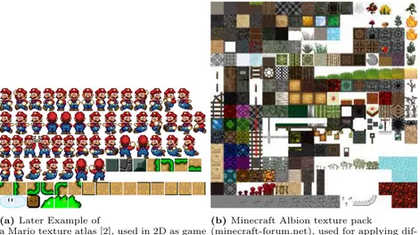
The method when you wrap bitmaps around a 3D model to simulate a certain appearance of that 3D model is called a UV-layout. The bitmap is usually called a texture. UV-layout and the wrapping of textures is referred to as texturing in this thesis. When designing textures for 3D models, artist commonly use two different techniques: tiling textures and part specific textures (figure 7). As an example a brick wall could use a tiling texture to simulate the brick material. A game character, on the other hand, is often a specific texture used for that model.[53] 2D games, e.g. Mario©series [2], often use a texture atlases as the example in figure 8a. Although 3D games also uses texture atlases extensively, a well known example being Minecraft©[25]. Example of a texture atlas used in Minecraft is seen in figure 8b
Figure 7: George character from the game Smaller©(ragehog.com). The image shows how a complex 3D model can have the UV data layed out onto a texture.
(a) Later Example of
a Mario texture atlas [2], used in 2D as game objects and animation sequences.
(b) Minecraft Albion texture pack
(minecraft-forum.net), used for applying dif-ferent materials on 3D objects in a 3D game. Figure 8: Example of texture atlases with different use cases.
An evolution of the texture atlas is the trim-sheet texture, where tiling tex-tures is combined into one single bitmap. Figure 9 show sci-fi materials win horizontal strips distributed onto several texture maps, albedo, normal, glossi-ness, spec, height, ambient occlusion and opacity. the main advantage of this approach is the saving of GPU overhead, as memory and draw-calls.[16, 53]
Figure 9: A trim sheet. The material strips can be utilised with adaptive UV-layouts.
3
Research methodology
This paper follows the design science research methodology (DSRM) defined by Peffers et al. [23]. DSRM gives a structured way to approach a Computer Science (CS) problem from problem identification to artifact evaluation, in other words a problem-centered approach. This suits this project well because of the problem solving and evaluation nature of a PCG projects [48] and the developed artifact. The DSRM process is broken down in the following steps:
1. ”Problem Identification and Motivation: Define the specific research prob-lem, and justify the value of a possible solution. The problem definition will shape the solution, so atomizing the problem may be useful in order to find a possible solution.”
2. ”Define the Objectives for a Solution: Here one should infer the objectives of a solution from the problem definition established in step 1, with knowl-edge of what is possible and feasible. The objectives can be quantitative or qualitative.”
3. ”Design and Development: During this step the artifact is created. This activity includes determining the artifact’s desired functionality and its architecture and then creating the actual artifact.”
4. ”Demonstration: Demonstrate the use of the artifact to solve one or more instances of the problem. Could be by using it in experimentation, simu-lation, case study, proof, or other appropriate activity.”
5. ”Evaluation: This activity is used to observe and measure how well the artifact supports a solution to the problem. This involves comparing the objectives set in step 2, with the gathered results from where the artifact was used in step 4.”
6. ”Communication: The final step is communicating the problem and its importance, the artifact, its utility and novelty, the rigor of its design, and its effectiveness to relevant audiences.”
3.1
How the methodology is used
Problem Identification and Motivation
There is a lot of research in generation buildings for games. Commonly used of CGA [20, 22, 35, 41, 44], CGA++ [41] or more recent like the WaveFunc-tionCollapse [54] algorithm. However, many of them are offline7generators, not generating floor plans, producing to much mesh data and/or not focused on texturing and UV-layout8. This work shows a developed artifact that addresses
all(4) of these issues.
Define the Objectives for a Solution
The goal is to create an artifact that can produce complete buildings. Complete, in this context, means buildings with exteriors and interiors suitable for a game environment. The developed artifact explores following quantitative objectives: 1. Using mathematical calculations in the generation process in order to
achieve online9 performance.
2. Using same calculation techniques in the entire production pipeline in generating both floor-plans and exterior (fa¸cades and roofs).
7Offline in the context of high generation times
8UV-mapping is the 3D modelling process of projecting a 2D image to a 3D model’s
surface
3. Reducing mesh data by simplifying the triangulation process.
4. Automating texturing layout to reduce GPU rendering speed and memory load.
The developed artifact also explores these qualitative objectives, explained in section 4.2:
1. Complete buildings as in ’enter-anywhere’.
2. Congruent buildings as in plausible building parts.
3. Consistent buildings, i.e. buildings that are complete and congruent. Design and Development
The artifact is developed using the Unity©Game Engine[57] (Unity). Section 4 (Implementation) gives a detailed description of the creation process but the different artifact modules is summarised as follows:
1. PM used for generating edges and calculating angles, intersections, fea-ture10 placements, offsets etc.
2. Operation stack(s) that are instructions used as input for the polygon creation.
3. Triangulation mathematics for creating mesh and UV data from polygons. 4. Mesh generation algorithms.
5. Automated texture placements using polygon data via the triangulation process.
Demonstration
The artifact is demonstrated by changing the rules and the inputs producing diverse buildings. These buildings can also be used for evaluation i the next step.
Evaluation
The generated buildings is evaluated by using an expressive range analysis [27, 48] changing several input parameters to generate several building outputs. Be-cause of the parameter driven approach and the use of score calculation for the output measure consistent, the expressive range evaluation analysis is chosen as a method for examining the capabilities of the generator. The input parameters with the most influence on the consistent measure is examined further using point plots for correlation detection.
Communication
The developed artifact utilises a novel approach on using PM in creation building features with layers in the generation pipeline. The polygon and layer approach gives the generator a short generation time, limited triangle count, and simplified texture implementation. Furthermore, as the generator is parameter driven with a lot of different parameters, degree of controllability is high for the end user. Finallly, to enhance the controllability further an operation stack is introduced for detailed control of the polygon creation process.
3.2
Methodology discussion
Due to the need to solve a problem of generating 3D buildings for games, with the use of PM, based on previous research, the design research methodology by Peffers et al. [23] would provide a structured and proven process for solving and presenting a solution to the problem. By applying evaluation methods from Shaker et al. [48] it is possible to generate and present metrics that measure building consistent values(see section 4.2). This enabled measurement of the viability of the design towards the output metrics and also makes it easier for further research in this area to compare their results with the ones presented in this paper.
Other research methodologies is considered and evaluated to fit this project, such as surveys or case studies [18]. As the aim of the artifact is a generalisation of algorithms that can use polygon mathematics for the generation purposes, the survey strategy as a research methodology do not fit well, as surveys mostly is an interview or observation based methodology. Moreover a case-study uses an existing phenomena or artifact as the base of the study and the fact that the developed artifact is new, makes this methodology a bad choice as well.
4
Implementation
4.1
Engine
The artifact11is developed on the Unity©Game Engine [57] (Unity), which is a
cross-platform developer environment for 3D applications. Unity©has a mesh generation system and material framework suited for this project as well as a system for writing user interface (UI) implementations for the editor part of the engine (editor). To change parameters in the editor without running the game scene speeds up the developing process and helps the end user create building faster. The operation stack, with the ordered list, is especially helped by Unity’s Application Programming Interface (API), that have a direct implementation of an ordered, with re-ordering implementations, list that can be used in the editor. Furthermore Unity has a broad user base and that will help in any future marketing attempts.
4.2
Consistent buildings
To define what a building with fa¸cades and floor plans is, in the context of a generated 3D model, a definition from Tutenel et al. [32], 2011, is used. They
present three main characteristics for game relevant 3D buildings:
1. ”complete buildings, i.e. ’enter-anywhere’ buildings consisting of not only a fa¸cade, but also interiors, stairs, furniture, etc. ”
2. ”congruent buildings, i.e. buildings with plausible elements in harmony and without conflicting elements.”
3. Buildings that are both complete and congruent are considered consis-tent.
4.3
Goals and visuals
The goal of this project is to generate 3D models of buildings suitable for a game environment. The buildings are consistent, with floor plans, fa¸cades, roofs, windows, doors other details and surface textures, and have small performance impact so that they can populate a small village. Furthermore the intended texture system, with trim-sheet textures, allow for flexibility in the appearance of all the rendered objects. The automated UV12placement makes it easy to
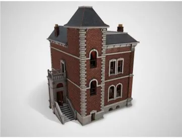
replace surface materials for e.g. a fa¸cade or a window. However the visual goal for this project is a simplified Victorian Style13(VS) house similar to the house shown in figure 10, but with material replacement possibilities as described.
Figure 10: Example of intended visual style (www.cgtrader.com). This building shows the artifacts in-tended style for fa¸cade and roof materials, the shape of the roof and to a certain extent the look of the windows.
The supplied textures for the complete artifact is based on this visual theme. Another example of the intended visual style is shown in figure 11. This building shows the intention of surface materials and window visuals for the developed artifact. The roof shape of the house also show the mansard roof style.
12UV-mapping is the 3D modelling process of projecting a 2D image to a 3D model’s
surface
Figure 11: Image from www.3dexport.com. The building ex-amplifies the intended style for fa¸cade- and roof-materials and windows- and door-shapes.
The VS is explored by Edward N. Kaufman, 1987 [6]. He explains the VS Architecture in the context of art or conveying meanings for the viewer and/or the placement in the landscape. The nature was often encoded into the buildings as ornaments or materials. For this project the style is is simplified, and to the authors personal preference, to generate
• Fa¸cades in stone or clay bricks similar to the 3D model shown in figure 10 and 13. The clay bricks and stone materials is common in VS and gives the correct feel to the artifact. In figure 10 the clay brick fa¸cade enhances the VS style as the stone material does in figure 11. On the contrary a wooden material, as seen in figure 12, does not get the intended VS style (authors opinion).
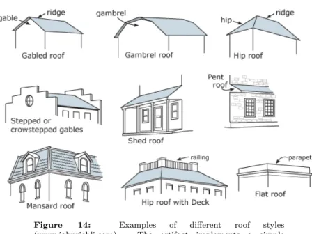
• Mansard or Hip roof with deck as shown in figure 14. Figure 10, 11 and 12 shows implementations of the hip roof with deck. A mansard roof deck is chosen because of the easy implementation int the artifact (it only requires a scaling of the base polygon inwards).
• Doors and windows is be simplified to styles shown in figure 11 because of time limitations of the complete project.
Figure 12: Example of intended visual roof style (jon-ake920.wordpress.com, 2013). The wood material shows a fa¸cade material that will not be used.
Figure 13: Blist Hill Lloyds Bank in Blist Hill Victorian Town (en.wikipedia.org). This is a real-world example of a clay briack material on a VS building for intended visual style.
Figure 14: Examples of different roof styles (www.johnriebli.com). The artifact implements a simple version of the Mansard roof.
Games that use models of VS buildings are many and differ of course in visual style. But Dishonered©series [33], figures 15a, 15b, Batham Arkham Knight©[42], figure 16a, and Assassins Creed Syndicate©[43], figure 16b, are games that represents the Victorian style in a fantasy world environment. In all three games the setting is very important the get the right VS look and feel. The games accomplish this with harsh town environments. The developed artifact does not go that far, but instead tries to mimic the visuals with the choice of textures for fa¸cade and roof.
(a) Dishonored 1 buildings use clay brick ma-terials in VS city setting.
(b) Dishonored 2 buildings use light grey stone materials in VS style. The material almost has a concrete look.
(a) The example from Batman Arkham Knight [42] is more about the feel and set-ting of a VS style.
(b) Also the snap-shot from Assassins Creed Syndicate [43] shows VS setting in a city filled with VS styled buildings.
Figure 16: Victorian Style settings from two different games.
4.4
Design choices & General approach
To support the visual appearance of produced buildings the generator has been constructed with the following design approaches:
• A layered implementation were the layers is responsible only for the part they are generating. For example the base layout layer is only responsible for creating the data for the creation of the base mesh(es), in this case the inner floor. But a layer output can also be an input for other layers. E.g. The base layout output is used as an input to the fa¸cade layer for use in wall placement.
• As most features in a building, in this implementation at least, is straight walls or wall-like structures (windows, doors, floor, roof) an edge approach is chosen. A collection of edges is used to make outer extents of e.g. wall placements. Such collections is commonly called polylines [45] and closed14
polylines are often called polygons [45]15. As the polygons actually only
describes corner points, or vertices, they are very useful for calculation of mesh data. More on this in section 4.5.
• To keep the GPU texture memory [26] to a minimum the project is aiming on few textures and overlapping UV-mapping16[53]. Textures with strips
or patches of materials is produced and the mesh UV-coordinates is placed in the correct material ”slot”. It is possible to fit any number of UV’s into every strip. This is illustrated in figure 34 at section 4.5.
4.5
Building Generation Procedure
The developed artifact generates buildings in 3D following a process described in the flowchart in figure 17 and is elaborated in the following sections.
14closed is when the start point of a polyline is the same point as the end point
15Polygons can in graphic terms also mean the rendered surface of a mesh part, but is
really the same thing: a closed loop of vertices.
16UV-mapping is the 3D modelling process of projecting a 2D image to a 3D model’s
Figure 17: Flowchart of the software’s generation pipeline. - The input process collects building metrics through a user inter-face and a set of rules.
- The building generator process uses the input metric and exe-cutes the data generation.
- The layers process is responsible for generating building data. - The Hierarchy generation process is creating a tree structure in Unity©[57] for placement of building components.
- The mesh generation process is responsible for producing meshes for rendering on the GPU.
- The rendering uses Unitys©built in rendering capabilities to vi-sualise the complete building.
Input
The input part of the flowchart (figure 17) has several metrics for building rules, a couple of operation stacks and material hooks. The Building Generator is responsible for these metric, see section 4.5. Figure 18 shows the application user interface (UI) with some of the metrics and layers visible. Not all the metrics are included in the UI.
Figure 18: Application user interface (UI) - Part 1(2). The first part of the UI contains a small setup part for setting the seed and the game object prefab used for populating the hierarchy. The layer base layout is controlled here to and contains the operation stack for the base polygon. The interior layout controls the room distribution through the wall operation stack.
Figure 19: Application user interface (UI) - Part 2(2). In this part of the UI the Fa¸cade is created through metrics that control window and door placements. The roof metrics control how high the roof should be and how much it should stick out outside the fa¸cade. Finally the details layer control all metrics for windows and door, e.g. materials, frame thickness, glass position etc.
Building generator initialisation
The building generator initialisation (figure 17) is responsible for storing all input metrics and running through the data generation process. This is done in several steps (layers) for different building parts as seen in figure 18 and 19. The initialisation metrics include: thicknesses, heights, widths, start posi-tions, material scales, material trim positions etc. for all building components. The building generator is also responsible for running all component-generators (layers) and for executing them in the correct order.
Layers: Polygon generation
For each layer input data is provided by instructions from an operation stack, Building Generator metrics and/or data from the preceding layer. Polygons and/or polylines are created based on this data and is used for holding placement
data for walls and details. An example of a generated polygon is shown in figure 20, created using the operation stack in figure 21. The polygon is subdivided into triangles, more on this in next section.
Figure 20: Base polygon with subdivision created using the op-eration stack in figure 21.
The operation stack The operation stack is an edge (wall) building in-struction stack (list) for generating polygons and/or polylines. The operation stack(s) is feeding the polygon algorithm with instructions with data on how the polygon should be created. The stack injects one stack member at a time into a polygon creation system (factory) and the factory decides how to handle that injection. Consequently, the system has a flexibility on choosing which factory method to use in combination with different operation stacks.
In the case of the base operation stack (figure 21 flow, the factory method expects a collection of angles and distances (an operation stack) and processes each operation internally in the method. The angle represents the direction of an edge based on the previous edge and the distance is the length of an edge. Every step in the stack creates a vertex and an edge in the polygon. At end of a stack sequence, the polygon closes (creates an edge between the last vertex and the first). Changing the values and the ordering of the members has a major impact on the building generation, which is shown in the Experiment section (5).
The factory method for creating internal wall in a room-layout instead ex-pects a wall operation stack as the one shown in figure 22. The factory creates single edges (walls) instead of closed polygons, and looks for intersections be-tween walls in a predefined direction. The algorithm follows these steps for each member in the stack to create room walls:
1. The edge index value gets the edge from the base polygon with the same index.
2. The edge distance value places the start of the room wall at a normalised distance (0 to 1) at the selected base edge.
3. The room wall is checking for intersections with other edges (room walls or base edges) in the angle, from stack member, direction.
4. A room wall is created from start at base edge to intersection.
Figure 21: Base operation stack example. The configuration shown in the stack was used to create the polygon in figure 20
Figure 22: Wall operation stack example
Layers: Triangulation
This part of the process creates triangle data from polygons or polylines for use in mesh generation. The triangulation process differ depending on what type of building part is to be created. Floor and roof(s) use a method called fan-triangulation [45] and the walls use simple quad-splitting [45]. The trivial approach for a fan triangulation is by picking an arbitrary corner (vertex) in the polygon and connect every other vertex, except the two closest, with an edge. The result is triangles with one common vertex, illustrated in figure 23a. However, this method only works for convex polygons, a polygon where all corner angles are less than 180°[45]. For polygons with exactly one concave corner, angle larger than 180°, that corner must be chosen for the algorithm to work. Otherwise the result could be intersecting edges as seen i figure 24, two last pictures from the left. A concave fan-triangulation is shown in figure 23b.
(a) Convex fan-triangulation.[45]
(b) Concave fan-triangulation.[45] Figure 23: Triangulating convex and concave polygons
Triangulation of quads i much simpler and is actually a fan triangulation of a polygon with 4 vertices (see 24b) [45]. The developed generator is solely capable of triangulating polygons with one or none concave corners (as in figures 24a, 24b and 24c), a triangulation as the one shown in figure 24d is not implemented. As an example, a polygon triangulated within the software is shown in figure 20. (a) Convex triangulation (b) Convex triangulation (c) Concave triangulation (d) Concave triangulation Figure 24: Triangulation examples
Layers: Mesh data
Every part generation results in data used for creating and rendering meshes. This data is stored in mesh data containers available globally in the generator software. The mesh data specifically consists of:
• Vertex positions in 3D space, calculated from polygon vertices, section 4.5 and/or building rule metrics, section 4.5.
• Triangle indices, retrieved and reorganised from triangulation data (sec-tion 4.5) to match the correct index order for the vertices. This is impor-tant for the GPU so that the rendering process function properly. • UV-layouts matching the vertex positions so that a texture (material) is
Hierarchy generation
When the data generation is complete, through the layer iterations, a tree-structure of building components is constructed. The software make use of Unitys©[57] built-in Gameobject instantiating feature. The feature can build hierarchies of Transforms with proper parent/ child relations and is useful for adding, removing and translating building parts on a per parent to child basis. The system generates a transform tree as illustrated in figure 25. Every leaf (green) in the tree contains one or several rendered components.
Figure 25: Generated structure
The first polygon generated in the layers iteration in section 4.5, is a polygon for the outer edges of a building. This polygon is the base for many of the following parts in the layer iteration and will be referred as the base-polygon. The floor component is generated from the base-polygon using fan-triangulation. Figure 26 shows an example of a generated floor with a wooden texture. The Ceiling is using the same base-polygon as the floor, but the triangulation is reversed. Mesh data for a GPU is dependent on the creation order of a triangle in order to render correctly depending on which side of the mesh the camera is viewing. Figure 27 shows a generated ceiling, but triangulation i not reversed for visibility purposes.
Figure 26: An example of a generated floor from a base-polygon
Figure 27: A ceiling generated from the base-polygon, but not reversed for visibility purposes.
The floor-plan, or the room-layout, is also using the base-polygon, as de-scribed in the operation stack example, to create walls for room separation. When the layout is complete, an intersection check is done and door features are incorporated into the polygon data. Figure 28 illustrates an example of a
floor-plan showing a generated mesh in figure 28a and an illustration, in figure 28b, of the intersection and door generation in the polygon process.
(a) A generated floor mesh with some nice wall paper texture
(b) This illustration of several wall polygons (polylines really), shows intersections (yellow circles) and door placements (purple squares) Figure 28: Floor plan
The Fa¸cade generation uses the edges from the base-polygon to extrude walls, with the introduction of two new polygons: one offsetted inwards for the inter-nal walls and one offsetted outwards for the fa¸cade walls. The process inserts feature, doors and windows, data into the polygons with preparations similar to the interior process. The method keep track of internal walls for not placing features in wall intersection, illustrated in figure 29.
(a) A generated fa¸cade mesh with a clay brick material.
(b) Fa¸cade polygon, with the internal wall intersection data visible (yellow circles) Figure 29: Fa¸cade generation example
A different method is used when creating the roof polygons and the roof mesh, even though the base-polygon is used in this process as well. The base mesh is offsetted twice to produce two new polygons. One is offsetted inwards to represent the top of the roof and the other polygon is offsetted outwards to
represent the end of the roof. A generated roof, in figure 30, from the software illustrates the process. The inner polygon is triangulated and a top mesh is generated and both the inner and outer polygon is connected with triangles to create the slant of the roof.
(a) Roof mesh, generated from the polygon in figure 30b.
(b) An inner and outer polygon is triangu-lated to connect and produce mesh data for the mesh in figure 30a
Figure 30: Roof generation example
Finally, as for the hierarchy generation, details are created using the fea-ture placement data from previous steps in the base- and walls polygons. The software generates polygons, with triangulation, for each detail part. From the polygons meshes are generated and textures applied (UV-mapped) in the next step in the process, which is illustrated in figure 32 where the polygons are seen simultaneously as the textured window meshes. Similar creation techniques is used to create doors and is visualised from an inside view in figure 31. The details, doors and windows, is positioned and rotated in place using the feature data from base- and walls-polygons and the result is a complete rendering of details in a complete building, as visualised in figure 33.
(a) Generated door
(b) Generated door with a window on the other wall
Figure 31: The software renders a basic door implementation
(a) Generated window from the outside (b) Generated window from the inside Figure 32: Polygons in white is used to create the window meshes.
Figure 33: Windows and doors generated by the software in a building with a clay brick fa¸cade.
Mesh generation
The mesh generation process creates building parts by generating meshes from the stored mesh data (section 4.5. The parts are combined to complete buildings incorporated into the generated game-objects structure in previous step (section 4.5), using Unity’s©[57] built-in mesh system, creating and storing meshes and sending them to the GPU for rendering.
Texturing
Trim sheet texturing The trim-sheet texturing utilizes a technique of plac-ing the mesh maps in correct material strip on a trim-sheet texture. UV-mapping is the 3D modelling process of projecting a 2D image to a 3D model’s surface for texture mapping. Trim-sheet textures are bitmaps that contain strips of a specific material, e.g. wood, brick, metal plates. Example shown in figure 34. To show how this works using the developed trim-sheet algorithm a visual-isation of a door is, in figure 35 and 36, showing the door parts, sides and door blades, placed in two different wooden materials.
Figure 34: Example of trim sheet. The different strips are color overlayed for visibility purpose.
Figure 35: A door model generated by the software, showing the UV’s layed out in a material strip. This figure show the door with a light colored wooden material.
Figure 36: A door model generated by the software, showing the UV’s layed out in a material strip. This figure show the door with a dark colored wooden material.
Tiled texturing is used for floor, ceiling and roof surfaces, because of the developed trims-heet implementations limitations when tiling large surfaces and maintaining material resolution. A floor mesh exemplifies the tiled texture placement for large surfaces in figure 37.
Figure 37: A floor mesh is UV-placed over a wooden planks texture. Notice that the texture is not covering the entire floor in the UV-space, the tiling for the material is taking care of that when rendering the mesh.
Rendering
The generated meshes is rendered, visualised, on screen through Unity’s©mesh rendering, which has two main parts:
• The Mesh Filter that has a container for the mesh and is responsible for the link between the Mesh Renderer and the actual Mesh.
• The Mesh Renderer visualises the Mesh on screen and is responsible for: shader and material injection to the GPU, special lighting conditions, and how to calculate occlusion culling for hidden objects.
4.6
Visual results
This section will discuss the visual appearance of some generated buildings, hence the figures show the general capabilities of the software more from an artistic perspective, rather than a technical. The discussion also contains a reflection on how the visual goal for the generator was achieved, with regards to a VS, and that reflection will be further analysed in the Discussion (7) section below. Moreover, as this is a visual presentation, the author’s opinion is reflected in the text as what ”good” visuals are.
Figure 38: Visual result from developed software showing a clay brick texture fa¸cade and stone frames for windows and doors.
Figure 38 is an example of a building with elements that resemble aspects of a real-word VS building. The clay bricks, according to the author, sets the character of the VS look together with the brownish roof. However, the lack of details, e.g. ornaments and window protrusions, hold the VS feeling back.
Figure 39: With a simple change to a material trim value, the surface materials is changed resulting in a light colored plaster fa¸cade.
The building in figure 39 has the appearance of an office building, more than a VS building, but it is a good representation of the diversity potential of the generator. Simple changes to the input values can alter materials and building layouts completely. The building in the image has plaster material for
the fa¸cade and dark wood material for windows and doors.
Figure 40: A generated building showing wooden material for the fa¸cade, door(s) and windows
The software is not only capably of visualising VS buildings, but, depending on material choice, buildings of other types can be generated as well. The build-ing in figure 39 was with three simple steps, removal of operations, shortenbuild-ing of walls and shifting strip in the trim-sheet, transformed into the cottage in figure 40. An inside view of the cottage is shown in figure 41, with wall-paper texture and flooring.
Figure 41: The inside view of the building in figure 40, with pink wallpaper and wooden frames.
5
Experimental setup
Considerations were made to use smoothness- or codependency analysis for the experiment evaluation as described by Cook et al. [56], 2019. The method compares input values to look for dependencies rather than focus on the output as in expressive analysis. Due to the visual output for the developed build-ing generator a individual parameter analysis approach is a better choice than smoothness- and codependency methods.
Danesh [49] is a tool that helps visualise an expressive range evaluation. Us-ing this in the experiment could have helped in understandUs-ing the connection between input parameters and the generated buildings. However, the implemen-tation and feature of the operations stacks incorporated into Unity [57] UI do makes it hard for this tool to be used with the operation stack implementation introduced in this thesis. AS the building generator is parameter driven via input metrics, it is evaluated changing several input parameters to generate a number of building outputs. Furthermore the analysis investigates correlations between inputs and outputs by analysing input parameter(s) with the greatest impact on the building outputs. However, one problem with this approach could be to choose the correct input parameters, if you can’t use all of them. The setup in this experiment tries to cover as much inputs as possible using them in three different building configurations (templates), with different building characteristics as wall height, window sizes, roof slant etc.
5.1
Experimental setup:
Evaluating the consistency of
buildings
Consequently the analysis starts with three templates, which are altered via input parameters to give variations of those buildings. The templates are indi-vidually analysed with different set of input parameters taken from the opera-tion stacks. Finally the building data is compiled and the generators expressive range is discussed with regards to building consistency (section 4.2. The setup is explained i detail below.
The building templates
The experiment make use of three different building templates, with settings of building metrics shown in table 1. For Template 1 (T1) the values of the metrics are low for the purpose of generating small walls, windows and doors (features). Template 2 (T2) has metrics close to real-world building dimensions generating buildings with feature sizes in between Template 1 and Template 3. Finally Template 3 (T3) is a high-value extreme template with large features and large walls. The templates are used in the experiment when altering parameters in the two operation stacks, base operation stack and wall operation stack. All
Table 1: Table of building templates used in experiment. All numeric values refer to Unity game engine 3D units (u.u.). Template 1 is a metric of low-value extremes,
Template 2 is a base building with dimensions common in real-world buildings and Template 3 has high-value extreme metrics.
Building Metric T1 T2 T3 Range min - max Wall height 2.2 3.2 4 2.0 - 4.0 Outer wall thickness 0.1 0.5 0.7 0.1 - 1.0 Inner wall thickness 0.1 0.3 0.5 0.1 - 1.0 Window size 0.5 x 0.5 0.8 x 1.5 2.0 x 3.0 0.1 - 3.0 Window pos. above floor 1.0 1.2 0.8 0.0 - 4.0 Max no. of windows/wall 1 3 5 0 - 5
Door size 1.1 x 2.0 1.3 x 2.2 1.5 x 3.0 1.0 - 3.0 Window/ door lining width 0.03 0.1 0.3 0.01 - 1.0
Roof slope distance 0.5 1 2 0.0 - 5.0 Roof overhang distance 0.3 0.4 0.6 0.0 - 1.0 Based on the input values of each template we get buildings that can have a look similar to the ones shown in figures 42a, 42b and 42c. Henceforth these are referred as setup building(s).
(a) Input values for T1 gives this appearance in
the experiment setup
(b) Input values for T2 gives this appearance in
the experiment setup
(c) Input values for T3 gives this appearance in
the experiment setup
Figure 42: The template buildings
The operation stacks
To finalize the experiment setup, some input metrics from the operations stacks of the building generator is used. They are shown in table 2 and 3. The base operation stack controls the base shape of a building and the wall operation
stack controls the interior walls of a building layout. Not all inputs are used in all templates, which input is used in which template is also shown in the tables. The experiment iterates values for order of operations, angles and distances for both stacks and wall index for the wall stack. Figures 43 and 44 shows snapshots of stack configurations from the application UI.
Figure 43: Base operation stack example.
The Angle Value controls the wall direction in the base polygon The Distance Value controls the actual wall length.
The order of the operations is important due to the previous gen-erated walls.
Figure 44: Wall operation stack example.
The Edge index tells the generator which outer wall the inner wall should attach to.
The Edge Distance controls where the attachment should start on the outer wall ranging from a value 0f 0 to 1.
The Angle Value controls the direction of the actual inner wall
Table 2: Input metrics from the base operation stack. Order: Order of operations in the stack.
Angle: direction for the wall in local orientation. Distance: Wall length
Base operation stack metrics Input values Used in Order of operations -2 to +2 (neg = up, pos = down) T1
Angles 10 to 170 T2, T3 Distances 0.1 to 25 T2
Table 3: Input metrics from the wall operation stack. Order: Order of operations in the stack.
Angle: direction for the wall in world orientation. Edge index: The outer wall to attach to. Edge distance: Where to start on that wall
Wall operation stack metrics Input values Used in Order of operations -2 to +2 (neg = up, pos = down) T1
Angles 0 to 170 T1, T3 Edge index 0 to 6 T2, T3 Edge distance 0 to 1 T2
5.2
Building Outputs: Generated in consistency
The output metric used for evaluating the generator is the concept of tency, it is discussed in section 4.2. In the context of this evaluation the consis-tence measure contains three main components, building defects, completeness and congruence. All building inputs are evaluated against this measure and all the details of the consistent content is explained in following sections.
Building Defects
The polygon algorithm used to generate a lot of elements in the software is capable of detecting errors (defects) in the generation process. The algorithm calculates four defects that can be used in our evaluation, the number of concave corners, Self intersection, overlapping corners and small edge angles. due to limitations in the triangulation process of the building generator more than one concave corner is not recommended. Although it is possible to generate consistent building with more than one concave corner, more than one concave corner counts as as a defect in this analysis. Self intersections occur when an edge direction or an edge length causes two or more edges to intersect. All these intersections are counted as defects as it will most likely cause a warped mesh. Overlapping corners is when a polygon vertex has the same location as another vertex in the same polygon. This will cause zero length edges and result in zero area meshes. All overlaps are counted as defects. Sometimes an operation in a stack can cause an angle between two edges to be so small that a straight edge would be preferable to not cause unnecessary wall generation. All angles between -5 and +5 are counted as defects. Possible values is also shown in table 4.
Table 4: Building defects outputs with possible values. A sim-plified description of defect outputs from the building generator base layout.
Defect type Possible values Concave corners > 0 Self intersections > 0 Overlapping corners > 0 Small angles > 0
Complete and Congruent
To evaluate buildings in terms of visual features as room distribution, accessi-bility to rooms, windows and door placements etc. can be subject to bias and personal preference. To reduce the bias the congruent and complete concept, as introduced in section 4.2, is extended to use some evaluation principles for score giving. The complete score is calculated as follows. Start at score 10. Use a probe cylinder with the radius 0.3 u.u and height of 2 u.u to check access to all rooms. Access can be denied by blocked doors, narrow corridors, collapsed walls etc. Reduce score by 2 for every denial. The congruent score is calculated in similar fashion. Start at score 10, Reduce score by 2 for any window/door intersection with another window or wall (occlusions). Also reduce congruent score for very small rooms, only just fitting the probe, by 1. A Simplified de-scription of the calculations can be found in table 5 and some complete and congruent scores visualised in figure 45.
Table 5: Complete and Congruent value calculation method.
Building score type Value calculation Complete = 10 − accessdenials ∗ 2
Congruent = 10 − occlusions ∗ 2 − smallRooms ∗ 1
(a) complete = 10, congruence = 10 All rooms accessible and no intersection
(b) complete = 8, congruence = 10 One corner in a room in-accessible and no intersection
(c) complete = 10, congruence = 8 A window intersection
(d) complete = 0, congruence = 0
Many in-accessible rooms and many intersec-tions
Consistent score calculation
For the consistent evaluation to be completed the building output evaluation for the consistent metric is calculated by the sum of complete and congruent divided by two. The value is reduced by number of defects. This gives a score that has a range from -4 to 10 and also shown in equation 5.2.
consistent = complete + congruent
2 − def ects (1) Generator loop-through speed
As a separate experiment, to evaluate the time for buildings to generate (loop-through speed), a number of buildings is created, with the T2 building template, using a computer with a 8th generation i9 CPU and a Nvidia GTX 1080 GPU. The time, in seconds, for the buildings to generate in sequence is measured. The amount of buildings generated starts at 1 and gets doubled up to 1024 buildings and that amount and the generation times is plotted in a graph shown in section 6.
6
Results
A total of 140 building were generated with inputs parameter values evenly distributed over the three templates. A consistent (or consistency) value was calculated using the formula in section 5.2. To investigate individual parameter influences to the consistency value a box plot was made (figure 46). Each box in the plot represents an input parameter from the experiment setup. Hence we can see the range of consistency values for different input parameters.
Figure 46: A box plot showing result from the generation pro-cess. Each box represents an input metric and the influence that metric has on the consistent value. A large box shows a large influence and a small box a small influence.
Based on the data in the box plot two point plots where made to investigate the correlation between the base operation stack and the consistent value, as those two input metrics seem to have largest impact on the consistent value. Hence, the angle and the order of the operations is plotted and is shown in figures 47 and 48.
Figure 47: Changes to the angles in the base operation stack shows a large impact on the consistent value. Angles in the plot are delta changes from the setup building.
Figure 48: Changes to the order of operations in the base opera-tion stack shows a large impact on the consistent value. Negative values for the order axis represents a move upward in the stack and positive values a downwards move.
Additionally, one more point plot, figure 49, was made to check correlation between the complete and the congruent scores.
Figure 49: A point plot containing congruent and complete scores shows high correlation between the two. 140 data points were sampled.
Finally, figure 50 shows generation times plotted against different in sequence generated amounts of the T2 building. The plot show the time, y-axis, it took to generate a certain amount of buildings, x-axis, in sequence. E.g. it took roughly 20 seconds to generate 1,000 buildings in sequence. The purpose of the plot is to investigate the generators speed when creating one or multiple buildings.
Figure 50: A plot containing generation time in seconds when generating different amount of buildings, based on the T2 tem-plate building. The purpose is to investigate the speed of the software when generating any amount of buildings. E.g. In the plot the time, y-axis, it took to generate 1,000 buildings, x-axis, is roughly 20 seconds.
7
Discussion
As described in the Related Research section, there is a substantial amount of research in and implementations for generating buildings in 3D. The developed generator in this thesis explored a novel approach in using polygon mathematics and operation stacks for generating consistent building layouts. Additionally the software used trim-sheet texturing to support the building outputs with surface material that is easily replaced through the user interface. Experiments were made to analyse the expressivity of the polygon based generator and this section will address the results gathered through the experiment in relation to the con-sistent metric and visuals of the buildings. The result data is then is analysed in order to discuss whether the RQ’s can be met or not. Through expressivity analysis we can further validate the data collected from the experiment, and also discuss factors that might have affected the actual results.
7.1
Analysing the generator based on the consistent value
The consistent value is dependent on the congruence and complete values so we examine the average values of the output metrics, but the defects . The average congruence value for all buildings is at 7.69, the complete value is at 7.99 and the consistent value is at 7.27. The explanation for the consistent value being lower that the other two is, of course, that it is dependent the defects as well. The defects has a large impact on the consistent value because of the
high amount of generated building for the experiment is in the defect range. In hindsight the experiment should have done a more spread out generation setup to catch buildings with lesser defects. The averages for congruence and consistent are very close together which indicate a codependency, more on that discussion below.
Continuing, some interesting observations can be made from the box-plot in figure 46. The order of operations in the wall stack, deciding which wall in the room layout that should be constructed first and should have (and has) a large impact on the room-layout, have no significant effect on the consistent value. That could be explained by a poor choice of stack member or input values or that the consistent value is a poor calculation for evaluating room layouts. In fact the wall operation stack is a poor contributor to the consistent value overall. Furthermore the templates seem to have minor effect on the consistent value. That is expected though, because of the building generation algorithm’s size check in placing features as seen in the Implementation section (4). On the other hand the base operation stack seems to have a significant contribution towards the consistent value and two point plots where made to investigate this correlation further. The angle and the order of the operations were plotted against the consistent value in figures 47 and 48 and the data confirms a high correlation. This is expected because of the layer-based implementation, that creates building parts based on the polygon, created by the base operation stack, from the first step of the pipeline.
To visualise changes to the operation stack two example building were made to show the effects of an operation stack change and it can be seen in figures 51 (before) and 52 (after). The sixth operation, counted from top of stack, is moved 4 steps up and gives a different building, however with errors (defects) but still rendering a consistent house.
Figure 51: A screenshot from the application showing a building before a change to the operation stack.
Figure 52: A screenshot from the application showing a building after a change to the operation stack.
In addition, the consistent value itself was evaluated by comparing the con-gruence and the complete values in a point plot (figure 49). The point plot indicates a high correlation between the two values. That shows that congruent and complete is to dependent on each other and could be merged into one metric or that more conditions are needed to separate them, with the latter being the better approach as it would increase the granularity of the output metric(s).
The experiment also shows that other inputs, as those changed in the setup buildings have a small effect on the consistent value, even though more data is needed to make a definite conclusion. Metrics in the template data could need further investigations, as they only have three different value changes due to three different templates.
To conclude the consistent value discussion tables 6 and 7 shows how dif-ferent changes to the wall- and base operation stacks effects the congruent and complete values and the visuals of some generated buildings.
Table 6: Examples of influences from changing the wall oper-ations stacks. The examples is based on the T2 template, but results are similar for T1 and T3.
Before stack change After stack change
Before a wall op-stack re-order. complete=10, congruent=10.
After a wall op-stack re-order. complete=10, congruent=9.
Before a wall op-stack index/angle change.
complete=8, congruent=10. Small room in corner.
After a wall op-stack index/angle change.
complete=10, congruent=10. Small room in corner is larger.
Table 7: Examples of influences from changing the base opera-tions stack. The examples is based on the T2 template, but results are similar for T1 and T3.
Before stack change After stack change
Before a base op-stack re-order. complete=0, congruent=0.
Building is warped due to self intersec-tions.
After a base op-stack re-order. complete=10, congruent=10.
Moving one of the operations fixed the problem.
Before a base op-stack angle change. complete=10, congruent=10. A common building footprint.
After an angle change to two members. complete=10, congruent=10.
7.2
Analysing the generation speed
A generation time plot, figure 50 was made to show the capability of real-time generation. 1,000 buildings took roughly 20 seconds to generate, which gives 0,02 seconds per building. That translates well to lower building counts all the way down to one building, as the plot is linear. The generation time of 0,02 seconds is above the time for one frame at a frame-rate at 60 fps (0,0167 seconds).
7.3
Analysing the trim-sheet texture placement
No experiments were done to check the trim sheet placement capabilities, instead the capabilities of the system and the visuals is described in the Implementation section (4). The main advantage of the trim-sheet textures approach, instead of a tile-based, is that the material count per building is lower, still keeping the possibility of a high resolution textured surface. The disadvantage is that if the user need to replace the material, the texture set of that material needs to be created to match the software to some degree. Even though the software is flexible in regards to the strip heights and number of strips per texture set.
7.4
Analysing triangle count per building
One goal for this software is to reduce the amount of triangles produced for each building compared to some of the generators in the Related research section (2), which have triangle counts towards 100,000. The developed algorithm in this software uses polygon mathematics calculating corners for each mesh and nothing more, as illustrated in figure 20, which makes the triangle count as low as it possible can be. There is no extra information in between vertices if it is not needed. Of course, the total number of triangles in a building is also depending on the number of building parts produced, a consideration made in the software, which only creates the mesh needed for each part, even though some enhancements could be made to combine some of these meshes into game objects, to keep game object count low. The relation between the triangle count and the size of the building is illustrated in figure 53 below, where a medium sized building has a triangle count below 1,500 triangles. For a large village populated with 150 buildings the triangle count would sum up to 225,000, which is an amount that any decent GPU and game engine can handle today. Furthermore as an extra advantage, is that they all use the same texture(s) on the GPU, reducing overhead, but with different surface material combinations rendered in the game scene.
![Figure 6: An example of a L-shaped building footprint with a central skeleton edge.[24] The edges of a polygon is collapsed into a central edge.](https://thumb-eu.123doks.com/thumbv2/5dokorg/3950691.74268/10.892.319.568.693.860/figure-example-building-footprint-central-skeleton-polygon-collapsed.webp)