MASTER'S THESIS
QoS of Mobile Broadband Users in
Heterogeneous Networks
Muthanna Abdulhussein
Master of Science
Computer Science and Engineering
Luleå University of Technology
QoS for Mobile Broadband Users
In Heterogeneous Networks
Muthanna Abdulhussein
Mobile Systems Master Program
Department of Computer Science, Electrical and Space Engineering
Luleå University of Technology
S-97187, Luleå, Sweden
December 2011
Supervisors
Stefan Wänstedt
Ericsson Research AB
Robert Brännström
ii
Abstract
Initial deployments of LTE networks are based on so called homogeneous networks
consisting of only Macro base stations for basic coverage. As the number of users increases, especially in densely populated areas, the macro base stations are believed to lack sufficient capacity to bear the load of traffic increase for mobile broadband users. To overcome this problem the macro network will be complemented with low power nodes, such as Pico and Femto eNBs, will improve the system capacity.
This Master thesis study comprises an investigation on how quality of service can be
maintained for video telephony users in heterogeneous networks when considering different configurations, user patterns, user distributions, and user loads.
Three heterogeneous configurations specified by 3GPP were compared to a reference case; a pure macro network. Firstly, the simulation results show that when introducing low power nodes (LPN), the video telephony capacity increases with the increase in the number of users clustered around the hot-spots for all configurations. Also, in the heterogeneous network users in the macro cells experience slightly lower interference when more users are absorbed by the low power nodes. The video telephony tail latency experiences a sharp increase for all configurations. The reason for this is that the worst cells become congested and the users will compete for the available resources. It is observed that the tail latency in uplink, already at low load, is higher than in downlink due to that the scheduler is located at eNodeB.
Secondly, a scenario investigating the gain of Low power nodes range extension showed that signal to interference and noise ratio (SINR) problems arise if the range of the low power nodes is extended, however the system as a whole observes increased throughput. The main reasons are macro layer offloading and reduced interference created by the macro layer.
Finally, a scenario investigating the addition of multiple Low power nodes cells with range extension showed that video telephony capacity will be further improved when multiple Low power nodes are combined with range-extension.
The combination of range extension and multiple low power nodes (LPN) will reduce the interference originating from the macro cells as a result of the offloading of the macro cells. This since more users will be served by the LPN cells. As a result, the macro physical resource block utilization will be reduced. It was shown also that the throughput of the LPN cells is not related to the number of deployed LPNs, but it depends on the size of the LPN cell increase of RSRP offset.
Preface
The work implemented in this master thesis is presented as a partial fulfillment of M.Sc degree in Computer Science and Engineering with an emphasis on Mobile Systems on behalf of Luleå University of Technology. The thesis work was carried out at Ericsson Research AB, Luleå for the period from March- December 2011.
2
Acknowledgments
I would like to express my thanks and gratitude to my supervisor, Stefan Wänstedt, for his valuable input, guidance and commitment through this project. He has been very supportive, cooperative and always prioritizes mutual discussion for the project.
I would like to warmly thank as well, Mats Nordberg, Manager of Optimization of IP over Wireless Access Networks, for giving me the opportunity to do my master thesis in Ericsson research corporate unit in Luleå and all his team members for the their continuous support in the initial stages of the work. Also I would like to thank Ericsson research corporate units in Kista in Sweden and Jorvas in Finland for their help and support. Finally, I would like to thank my supervisor in Luleå University of technology, Robert Brännström, and my adorable wife Marwah who has supported me during the completion of this project.
Table of Contents
Abstract……….. ... ii Preface……….. ... 1 Acknowledgments……… ... 2 Table of Contents………. ... 3 List of Tables……… ... 5 List of Figures……… ... 6 List of Abbreviations……… ... 8 1. Introduction... 101.1. Evolution of Mobile Network Generations ... 10
1.2. Problem Statement ... 11
1.3. Thesis Outline ... 12
2. Introduction to LTE...13
2.1. LTE Radio Access... 13
2.1.1. LTE Network Architecture ... 14
2.1.2. Radio Protocol Architecture ... 15
2.2. LTE Transmission Schemes ... 16
2.3. Time Domain structures ... 20
2.4. LTE Physical Resources ... 21
2.5. Downlink/Uplink Control Signaling ... 21
2.6. Scheduling ... 22
2.7. HARQ and soft combining ... 23
3. LTE Rel. 10 (also referred to as IMT-Advanced)...25
3.1. LTE Rel. 10 ... 25
3.1.1. Requirements for IMT-Advanced ... 25
3.1.2. LTE-A Spectrum Flexibility ... 26
3.2. LTE Rel. 10 Technical Features ... 26
3.2.1. Carrier Aggregation ... 26
3.2.2. Coordinated Multipoint Transmission (Comp) ... 29
3.2.3. Support of Heterogeneous Networks (Hetnets) ... 30
4. Heterogeneous Networks (Hetnets)………...31
4.1. Low Power Nodes Categorization ... 31
4.2. Heterogeneous Networks Deployment Challenges ... 32
4.2.1. Spectrum and Frequency Band Allocation ... 32
4.2.2. Self Organizing Networks (SON) ... 32
4.2.3. Backhauling ... 33
4.2.4. Handover ... 33
4.2.5. Interference ... 34
4.3. Hetnets Enhancement Key Design Features ... 35
4.3.1. Range Extension ... 35
4.3.2. Inter-cell interference coordination (ICIC) ... 37
5. LPN Deployment on 3GPP User Distribution………...40
5.1. Simulation Metrics ... 40 5.1.1. System Throughput ... 40 5.1.2. SINR ... 40 5.1.3. Interference ... 40 5.1.4. Video Capacity ... 40 5.1.5. PRB utilization ... 41
5.1.6. Average Uplink UE Output Power ... 41
5.2. Simulator Models ... 41 5.2.1. Traffic Model ... 41 5.2.2. Propagation Model ... 43 5.2.3. Simulation Parameters ... 43 5.3. Configurations ... 44 5.3.1. User Distribution ... 44
4
5.4.4. SINR ... 55
5.4.5. Average UE Output Power ... 58
5.5. Downlink Results ... 59
5.5.1. Video Telephony Capacity and Tail Latency ... 59
5.5.2. SINR ... 61
5.5.3. System Throughput ... 65
5.6. Conclusions ... 70
6. Impact of Range Extension on Hetnets………...71
6.1. Simulation settings ... 71
6.2. User Distribution ... 71
6.3. Uplink Results ... 72
6.3.1. Video Telephony Capacity and Tail Latency ... 72
6.3.2. Interference ... 74
6.3.3. System Throughput ... 75
6.3.4. SINR ... 75
6.3.5. Average UE Output power ... 82
6.4. Downlink Results ... 84
6.4.1. Video Telephony Capacity and Tail Latency ... 84
6.4.2. System Throughput ... 85
6.4.3. SINR ... 85
6.7 Conclusions ... 93
7. Multiple LPN Effect on Hetnets Performance...94
7.1. Simulation settings ... 94
7.2. Configurations ... 94
7.2.1. User Distribution ... 95
7.3. Uplink Results ... 97
7.3.1. Video Telephony Capacity and Tail Latency ... 97
7.3.2. Interference ... 98
7.3.3. System Throughput ... 99
7.3.4. SINR ... 100
7.3.5. Average UE Output power ... 103
7.4. Downlink Results ... 104
7.4.1. Video Telephony Capacity and Tail Latency ... 104
7.4.2. System Throughput ... 105
7.4.3. SINR ... 106
7.5. Conclusions ... 110
8. Conclusions and Future Work...111
8.1. Conclusions ... 111
LPN Deployment on 3GPP User Distribution ... 111
Impact of Range Extension on Hetnets ... 111
Multiple LPN Effect on Hetnets Performance ... 112
List of Tables
Table 4-1 Low power node categorization ... 31
Table 4-2 Hetnets evaluation with different range extension bias... 35
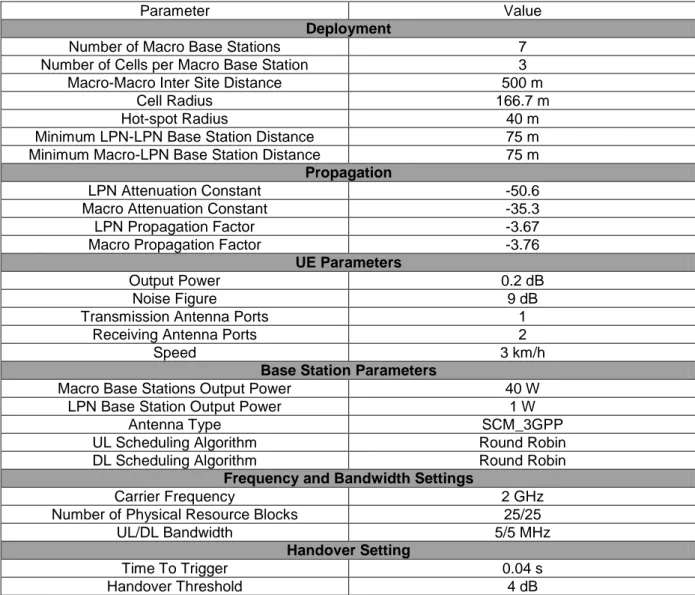
Table 5-1 Simulation Parameters ... 43
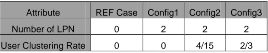
Table 5-2 3GPP Hetnets Deployment Configurations ... 44
Table 5-3 User Distribution ... 45
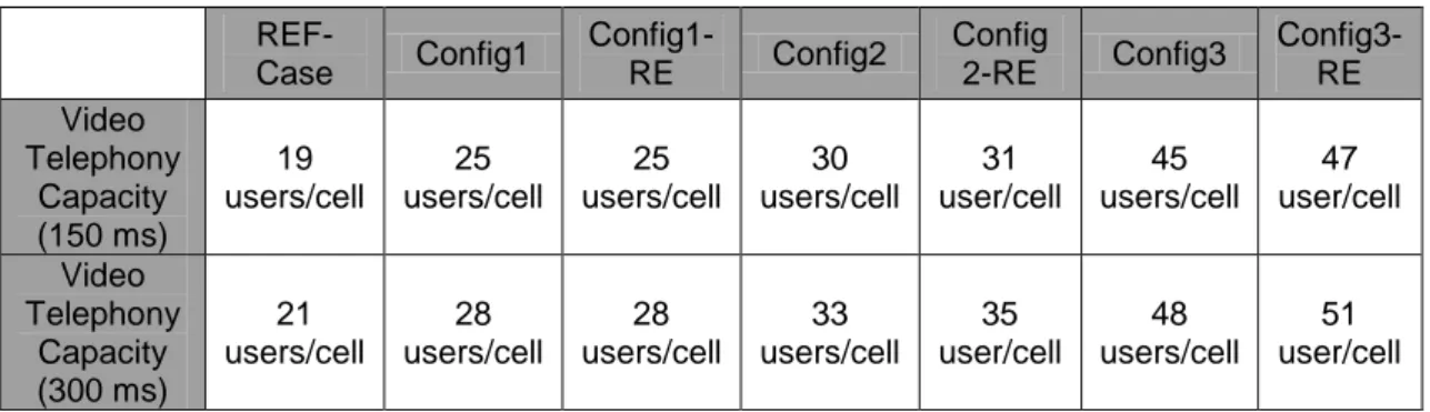
Table 5-4 Uplink Video Capacity and Tail Latency ... 47
Table 5-5 Downlink Video Capacity and Tail Latency ... 59
Table 6-1 Uplink Video Capacity and Tail Latency ... 72
Table 6-2 Downlink Video Capacity and Tail Latency ... 84
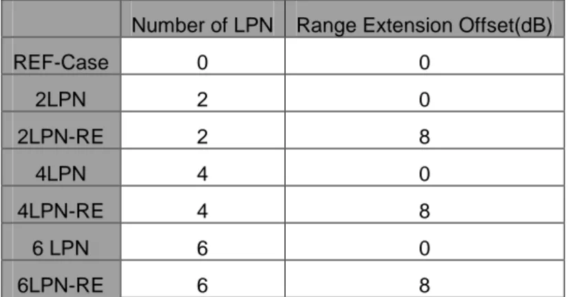
Table 7-1 Multiple LPN Configurations ... 94
Table 7-2 Uplink Video Capacity and Tail Latency ... 97
Table 7-3 Downlink Video Capacity and Tail Latency ... 105
6
List of Figures
Figure 2-1 LTE Spectrum and duplexing schemes ... 13
Figure 2-2 The LTE Architecture ... 15
Figure 2-3 LTE RAN Protocol Architecture ... 16
Figure 2-4 OFDM Sub-Carrier Spectrum ... 17
Figure 2-5 Cyclic prefix Addition ... 17
Figure 2-6 Time-Frequency representation to the OFDM Signal ... 18
Figure 2-7 OFDMA and SC-OFDM Transmitter and Receiver ... 19
Figure 2-8 Frame Structure Type1 and 2 ... 20
Figure 2-9 LTE resource grid... 21
Figure 2-10 The control signaling distribution ... 22
Figure 2-11 DL/UL LTE Scheduler ... 23
Figure 2-12 Parallel HARQ Process ... 24
Figure 3-1 3GPP Technology Evolution ... 25
Figure 3-2 Aggregation of component carriers in LTE Rel. 10 ... 27
Figure 3-3 Carrier Aggregation Architecture in LTE Rel. 10 ... 27
Figure 3-4 Spatial Multiplexing in LTE Rel. 10 ... 28
Figure 3-5 Comparison between traditional MIMO and COMP ... 29
Figure 3-6 General Deployment Scheme of Heterogeneous Networks ... 30
Figure 4-1 Hetnets frequency band allocation ... 32
Figure 4-2 Handover in Pico Cells ... 33
Figure 4-3 Dominant DL/UL Interference Scenarios ... 36
Figure 4-4 Time Domain Scheduling E-ICIC Technique in LTE-Advanced ... 38
Figure 4-5 Frequency Domain E-ICIC Technique in LTE-Advanced ... 39
Figure 5-1 Principle of User Distribution and Macro-LPN cell Layout ... 42
Figure 5-2 Macro-LPN User Distribution within Different Clustering Rates ... 44
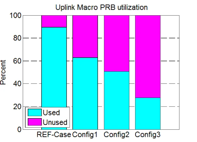
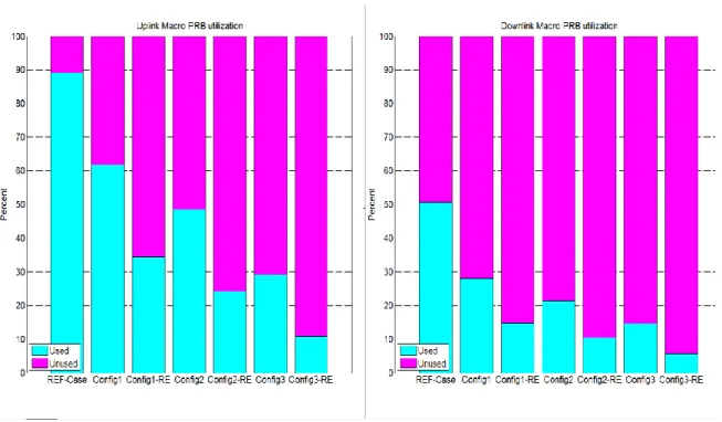
Figure 5-3 Uplink Macro PRB Utilization ... 45
Figure 5-4 Downlink Macro PRB Utilization ... 46
Figure 5-5 Average Uplink Video Tail Latency ... 47
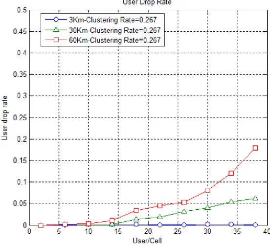
Figure 5-6 User Dropped Ratio ... 48
Figure 5-7 Average Uplink Video Tail Latency with different UE speeds. ... 49
Figure 5-8 Macro-LPN Average Interference ... 50
Figure 5-9 Average Uplink System Throughput ... 51
Figure 5-10 Uplink System Throughput of LPN Cells ... 52
Figure 5-11 Uplink System Throughput of Macro Cells ... 53
Figure 5-12 Uplink System Throughput of a Macro Cell Area ... 54
Figure 5-13 Uplink SINR of LPN Users ... 55
Figure 5-14 Average Uplink SINR of Macro Users... 56
Figure 5-15 Average Uplink SINR of All Users ... 57
Figure 5-16 Average Uplink UE Output Power... 58
Figure 5-17 Average Downlink Video Tail Latency ... 60
Figure 5-18 Average Downlink Video Tail Latency with Different Speeds ... 61
Figure 5-19 Downlink SINR of LPN Users ... 62
Figure 5-20 Downlink SINR of Macro Users ... 63
Figure 5-21 Downlink SINR for All Users ... 64
Figure 5-22 Average Downlink System Throughput of All Cells ... 65
Figure 5-23 Downlink System Throughput of LPN cells ... 66
Figure 5-24 Downlink System Throughput of Macro cells ... 67
Figure 5-25 Downlink System Throughput of Macro Cell Area ... 68
Figure 5-26 Macro eNB to Macro UE Distance ... 69
Figure 6-1 Macro-LPN User Distribution with Range Extension ... 71
Figure 6-2 Uplink/Downlink Macro PRB Utilization (Zero dB and 8 dB Offset) ... 72
Figure 6-3 Average Uplink Capacity and Tail Latency (Zero db and 8 dB Offset) ... 73
Figure 6-4 Macro-LPN Average Interference (Zero and 8 dB Offset) ... 74
Figure 6-5 Average Uplink System Throughput (Zero dB and 8dB) ... 76
Figure 6-6 Uplink System Throughput of LPN (Zero dB and 8dB) ... 77
Figure 6-7 Uplink System Throughput of Macro cells (Zero dB and 8dB) ... 78
Figure 6-8 Average Uplink SINR (Zero dB and 8dB) ... 79
Figure 6-10 SINR of the LPN Users (Zero dB and 8 dB Offset) ... 81
Figure 6-11 SINR of the Macro Users (Zero dB and 8 dB Offset)... 82
Figure 6-12 Average UE Output Power (Zero dB and 8 dB Offset) ... 83
Figure 6-13 Average Downlink Video Capacity and Tail Latency (Zero dB and 8 dB Offset) ... 85
Figure 6-14 Average Downlink System Throughput (Zero dB and 8 dB Offset) ... 86
Figure 6-15 Downlink System Throughput of LPN (Zero dB and 8 dB Offset) ... 87
Figure 6-16 Downlink System Throughput of macro cells (Zero dB and 8 dB Offset) ... 88
Figure 6-17 Average Downlink SINR (Zero dB and 8 dB Offset) ... 89
Figure 6-18 Average Downlink SINR of LPN users (Zero dB and 8 dB Offset) ... 90
Figure 6-19 Average Downlink SINR of Macro users (Zero dB and 8 dB Offset) ... 91
Figure 6-20 Average 5th Percentile Downlink SINR of Cell-Edge Users ... 92
Figure 7-1 Macro-LPN user distribution in Multiple LPN configurations ... 95
Figure 7-2 Uplink Macro PRB Utilization in Multiple LPN Configurations ... 96
Figure 7-3 Downlink Macro PRB Utilization in Multiple LPN Configurations ... 96
Figure 7-4 Uplink Video Capacity and Tail Latency ... 98
Figure 7-5 Macro-LPN Average Interference ... 99
Figure 7-6 Average Uplink System Throughput ... 100
Figure 7-7 Average Uplink SINR ... 101
Figure 7-8 SINR of LPN users ... 102
Figure 7-9 SINR of Macro Users ... 103
Figure 7-10 Average UE Output Power ... 104
Figure 7-11 Downlink Video Capacity and Tail Latency ... 105
Figure 7-12 Average Downlink System Throughput ... 106
Figure 7-13 Average Downlink SINR ... 107
Figure 7-14 Downlink SINR of Macro Users ... 108
8
List of Abbreviations
1xEV-DO CDMA2000: Evolution-Data Optimized-Code Division Multiple Access 2G: Second Generation
3G: Third Generation.
3GPP: 3rd Generation Partnership Project 3GPP2: 3rd Generation Partnership Project 2 4G: Fourth Generation
5G: Fifth Generation
ABSF: Almost Blank Sub-frames
ACK/NAK: Acknowledgement/Negative Acknowledgement AMPS: Advanced Mobile Phone System
ARIB: Association of Radio Industries and Businesses ARQ: Automatic Repeat Request.
B/s/Hz: Bits per Second per Hertz BTS: Base Transceiver Station CDF: Cumulative Density Function CDMA: Code-Division Multiple Access
CEPT: European Conference of Postal and Telecommunication Administrations CRS: Common Reference Signal
DFT: Discrete Fourier Transform DL: Downlink
DL-SCH: Downlink Shared Channel DWPTS: Downlink Pilot Time Slot
EGPRS: Enhanced General Packet Radio Services eNB: eNodeB
EPC: Evolved Packet Core
ETSI: European Telecommunication Standards Institute EU: European Union
E-UTRAN: Evolved-UMTS Terrestrial Radio Access Network FDD: Frequency-Division Duplex
FER: Frame Error Rate
FRAMES: Future Radio Wideband Multiple Access Systems GP: Guard Period
GPRS: General Packet Radio Services
GSM: Global System for Mobile Communications HARQ: Hybrid Automatic Repeat Request HD: High-Definition
HeNB: Home eNodeB
HSDPA: High-Speed Downlink Packet Access HSPA: High-Speed Packet Access
HSPA +: High-Speed Packet Access Plus HSS: Home Subscriber Server
HSUPA: High-Speed Uplink Packet Access ICI: Inter Carrier Interference
ICIC: Inter-Cell Interference Coordination IFFT: Inverse Fast Fourier Transform
IMT: International Mobile Telecommunication IRAT: Inter Radio Access Technology
ISI: Inter Symbol Interference ISP: Internet Service Provider
JTACKS: Japanese Total Access Communication System LPN: Low Power Nodes
LTE: Long Term Evolution LTE-A: LTE-Advanced MAC: Medium Access Control
MBMS: Multimedia Broadcast/Multicast Service MIMO: Multiple-Input Multiple-Output
MME: Mobile Management Entity NAS: Non- Access Stratum NMT: Nordic Mobile Telephony
OFDM: Orthogonal Frequency-Division Multiplexing OFDMA: Orthogonal Frequency-Division Multiple Access PAPR: Peak to Average Power Ratio
PCFICH: Physical Control Format Indicator Channel PCRF: Policy and Charging Rules Function
PDCCH: Physical Downlink Control Channel PDCP: Packet Data Convergence Protocol PDN-GW: Packet-Data Network Gateway PHICH: Physical Hybrid ARQ Indicator Channel PHY: Physical Layer
PMIP: Proxy Mobile IPv6
PRB: Physical Resource Block Utilization PUE: Pico User Equipment
QAM: Quadrature Amplitude Modulation QCI: Quality-of-Service Class Index
QCIF: Quarter Common Intermediate Format QoS: Quality-of Service
QPSK: Quadrature Phase-Shift Keying RACH: Random Access Channel RAN: Radio Access Network RB: Resource Block
RE: Range Extension REL: Release
RLC: Radio Link Control RLF: Radio Link Failure
ROHC: Robust Header Compression RN: Relay Node
RRC: Radio Resource Control
RSRP: Reference Signal Received Power RSS: Received Signal Strength
SAE: System Architecture Evolution SC-OFDM: Single Carrier OFDM SDMA: Spatial Division Multiple Access S-GW: Serving-Gateway
SINR: Signal-to-Interference plus Noise Ratio SMS: Short Message Service
TACS: Total Access Communication System TDD: Time-Division Duplex
TDMA: Time-Division Multiple Access TTI: Transmission Time Interval UE: User Equipment
UL: Uplink
UL-SCH: Uplink Shared Channel
UMTS: Universal Mobile Telecommunication System UPPTS: Uplink Pilot Time Slot
VoIP: Voice-over-IP
10
1. Introduction
1.1. Evolution of Mobile Network Generations
The development in wireless communications systems during the last decade has been tremendous. Cellular mobile communication systems were first introduced to the public in the early 1980s. The most famous of these first generation systems were NMT in the Nordic countries, AMPS in the United States, TACS in Europe, and J-TACS in Japan. The voice quality was not reliable with high probability of cross-talk between users being a dominant problem. These first-generation systems were analogue.
Later, the GSM system was initiated in the mid 1980s by the CEPT in Europe and later continued with ETSI. The GSM standard was built on TDMA. Somewhat later, a development of the CDMA standard, called IS-95, was completed in the United States in 1993. These 2G systems were limited in bandwidth, providing services such as voice; SMS and e-mail with a peak data rate of 9.6 Kbit/s. Higher data rates were introduced later in the evolved versions of 2G by assigning extra time slots (GSM) to users with modified coding schemes.
During the second half of the 1990s, packet data services became commonly used, e.g., GPRS and E-GPRS; often referred to as 2.5G. With these technologies, it was possible to reach data rates up to 114kbits/s in GPRS and 384kbits/s with E-GPRS by means of higher order modulation schemes.
The standardization activities for 3G commenced in ETSI in 1996 as a result of fruitful collaboration between a number of partially EU funded projects. Simultaneously, ARIB and FRAMES were developing the concept of WCDMA [32], which merged with the EU projects to become a part of the winning concept of UMTS; the European version of 3G ready in early 1998. With 3G, data rates up to 2Mbit/s were supported.
In 2003, 3G networks were upgraded to HSPA, which refers to two standards, HSDPA and HSUPA. HSDPA is the major addition in UMTS Rel. 5 while HSUPA was added in Rel. 6 [34]. The objective with HSDPA was to increase user peak data rates, reduce delays, and improve the spectral efficiency of the downlink. HSPA was designed to enhance the downlink and uplink transmission capacities. The theoretical peak data rate for HSPA in downlink is 14 Mbps while for uplink it is 5.8 Mbps.
In 2007, further enhancements were introduced through HSPA+ which was introduced in 3GPP Rel. 7. HSPA+ supports data rates up to 42Mbps in the DL and 22 Mbit/s in the UL by means of MIMO and high order modulation schemes; more feature have been added in Rel. 8,9[34].
The 3G evolution continued in 2004; a workshop was held to work on the 3GPP LTE radio interface. Requirements and design targets comprised high data rate at the cell edge, low latency in addition to the normal capacity; peak data rates and spectrum flexibility. LTE design targets were approved in 2005 [33]. By the end of 2005, 3GPP decided that LTE radio access should be based on OFDM in DL and DFT-OFDM in the UL [1], and by the end of 2007, the LTE specifications were approved.
Later, the work has continued on LTE, with the addition of new features in each release of the specification. By the end of 2008 the first release of LTE and EPC/SAE specifications in 3GPP Rel. 8 were ready. Rel. 9 was introduced by the end of 2009 and it included, among others, the LTE HeNB, location services, and MBMS support. In March 2010, LTE Rel. 10 [2] was introduced as a major step in the evolution of LTE, the most important features included in LTE Rel. 10 were support for carrier aggregation, enhanced multi-antennas, hetnets, enhanced ICIC, and relays. Work is ongoing now for Rel. 11.
According to a recent report by Morgan Stanley on Internet trends [3], the mobile services are expected to play a vital role in the evolution of Internet. The report estimates that mobile services users are expected to exceed the number of desktop users within 2014. The voluminous amount of traffic generated by, Social networking websites, VoIP, and HD Video applications on smartphones, will make the cellular operators run out of capacity even though LTE supports peak rates of 100Mbps. Moreover there is no current vision on 5G networks in the horizon at the moment.
1.2. Problem Statement
3G cellular operators are currently experiencing an abrupt increase in demand for mobile broad band services. The smartphones are now capable of transmitting HD videos and real time video conferencing traffic, (simultaneous UL and DL) which will definitely put high strains on cellular networks‘ access capacity. The IP infrastructure of LTE looks brilliant in terms of capacity and data rates, but on the long run, the cellular operators will probably need to monitor network load closely being prepared to upgrade; when awarding the users more bandwidth, they adopt different ways to consume the extra bandwidth and, eventually, loading systems beyond the capacity limit.
To improve capacity and coverage more sites should be added in the same cell site area; this since ―the bigger the cell site, the less capacity per user‖. With the smaller cells the capacity will be shared between fewer users and high rates are made possible. This concept is referred as network densification.
Network densification improves the spectral efficiency, but when new cells, with the same transmission power, antenna patterns, and backhaul connectivity, are deployed in
homogeneous networks, the deployment process will be complex and expensive; site acquisition of macro base stations with towers is expensive in urban areas. Given those limitations cellular operators are in need for a more flexible deployment model to improve the capacity and spectral efficiency per unit area, while simultaneously being cost effective. As 3GPP is continuously working to improve the LTE performance, the concept of Heterogeneous networks has been included in Rel.10 [4]. Heterogeneous networks imply deploying new base stations with different types of transmission power, antenna patterns, backhaul connectivity, etc. According to 3GPP 36.814 [5],the local macro cell layer will be embedded by low power nodes (LPN) cells placed in a more or less well planned manner to overcome the problem of coverage holes and enhance the spectral efficiency per unit area, thus improving capacity in hot-spot areas.
To a large extent, the obtained gains in coverage and capacity with mitigated interference scenarios are controlled by the location where the LPN is deployed, the user distribution, and the cell selection strategy. The deployment of LPNs in macro cell areas where users are clustered in so called Hot-spots is expected to offload some traffic from the macro cell. However, the interference is still a predominant phenomenon in such configurations, hence; a technique of range extension is applied to extend the LPN coverage, to further increase the number of users being offloaded from the macro cell.
This master thesis investigates the capacity of video telephony and analyses some QoS key performance indicators of mobile broadband users where LPNs are embedded within macro cells with different user distribution patterns.
12
1.3. Thesis Outline
Chapter 2 presents the main aspects of LTE as adopted by 3GPP including the radio access, network architecture, time domain structure, a detailed review of transmission schemes, DL/UL control signaling, DL/UL Scheduling and HARQ mechanism.
Chapter 3 discusses LTE Rel. 10 including requirements, spectrum flexibility, key design features such as carrier aggregation, enhanced DL/UL multi antenna support, coordinated multipoint transmission and the support of heterogeneous networks.
Chapter 4 gives a more extensive discussion on, heterogeneous networks comprising categorization, deployment challenges, key design features, as well as potential drawbacks. Chapter 5 provides results from a performance evaluation (capacity) of video telephony in heterogeneous deployment when considering a standard 3GPP user distribution.
Chapter 6 reports a study of the impact of range extension on a heterogeneous network with video telephony users.
Chapter 7 is an investigation of the impact of addition of multiple LPNs, the scenarios done in Chapters 5 and 6 will be taken further by investigating the effect of adding multiple LPN to the macro cell layer.
Chapter 8 summarizes all the conclusions from the studies performed in Chapters 5, 6, and 7 as well as provides suggestions for future work.
2. Introduction to LTE
2.1. LTE Radio Access
LTE, as it has been specified by 3GPP [5], is characterized by high bandwidth flexibility and simple receiver design, which makes it suitable for receiving high bit rates using large
bandwidth, up to 20 MHz. The peak data rate in LTE is 100Mbps in the DL and 50 Mbps in the UL with 20 MHz spectrum. LTE supports by both TDD and FDD. For TDD, LTE has a limitation that it cannot meet the high peak data bit rate requirement due to unavailability of
simultaneous UL/DL transmission; hence FDD is more efficient with LTE. An important requirement in the LTE design has been to avoid unnecessary fragmentation and strive for commonality between the FDD and TDD modes of operation while still maintaining the possibility to fully exploit duplex-specific properties, such as channel reciprocity in TDD as show in figure 2-1 [17] . Aligning the two duplex schemes to the extent possible does not only increase the momentum in the definition and standardization of the technology but also further improves the economy of scale of the LTE radio access technology.
The flat architecture of LTE has kept all the radio related functions needed for fast packet scheduling in the eNB, which contributed to 50% improvement in fast frequency domain scheduling when using OFDMA. OFDMA is defined as parallel transmission on large number of narrowband sub-carriers.
14
2.1.1. LTE Network Architecture
The LTE Network Architecture is shown in figure 2-2 [9]. E-UTRAN consists of base stations called eNB, which provides the user plane functions (PDCP, RLC, MAC and PHY), and control plane terminations towards UEs, e.g. including RRC. The eNBs are connected with each other via the X2 interface and towards the EPC via S1 [9].
The EPC is an evolution from the GSM/GPRS core network and supports access to the PS domain only. The EPC consists of the MME, S-GW, HSS, PDN-GW, and PCRF.
The MME and S-GW are connected via the S11 interface. The MME is connected to HSS via the S6 interface, while the S-GW is routed through the S5/S8 interface to PDN-GW. The eNB is responsible for cell resource management, broadcast information, MME selection, transfer of transparent NAS signaling (NAS is functional layer between the core network and the terminal that supports signaling and user data transfer), routing of user data to S-GW, intra-LTE handover, inter-MME handover, QoS realization and security as well as IP header compression.
The MME, i.e. the control plane node of EPC, is responsible for connection/release of bearers to terminals, NAS signaling, GW selection, roaming (S6a to home HSS), idle to active mode tracking, paging, inter MME and IRAT mobility, NAS ciphering and integrity protect.
The S-GW is a user-plane node connecting EPC to the LTE RAN. It is responsible for packet routing and forwarding, lawful intercept, LTE idle mode DL buffering, charging per UE, PDN, and QCI, bearer bindings for PMIP S5/S8 and also controls intra-LTE mobility anchor for other 3GPP technologies (GSM/GPRS and HSPA).
The PDN-GW is responsible for working as external IP point of interconnect IP address allocation, packet routing and forwarding, lawful intercept, as well as policy enforcement. The HSS is responsible for subscription data management, user identification handling, access authorization, keys for authentication and encryption, user registration management, as well as maintaining used PDN-GW.
The PCRF is responsible for service data flow gating, setting of QoS for each data flow, defining charging for each data flow, enabling bearer QoS control, correlating application and bearer charging, notifying bearer events to application function, as well as bearer bindings towards S-GW.
Figure 2-2 The LTE Architecture
2.1.2. Radio Protocol Architecture
The LTE RAN discussed in section 2.1.1 provides one or more radio bearers to which IP packets are mapped according to their QoS requirements. Figure 2-3 [19] depicts different protocol entities of RAN; the different protocol entities of RAN are:
Packet Data Convergence Protocol (PDCP) which performs IP header compression (based on ROHC [35]) to reduce the number of bits to transmit over the radio interface; PDCP is also responsible for ciphering and for the control plane, integrity protection of the transmitted data, as well as in sequence delivery and duplicate removal of data during handover.
Radio Link Control (RLC) is responsible for segmentation, concatenation, retransmission (handling duplicate detection) and in sequence delivery to higher layers. The RLC provides services to the PDCP in the form of radio bearers. There is one RLC entity per radio bearer configured for the terminal.
Medium Access Control (MAC) handles multiplexing of the logical channels, HARQ transmissions as well as UL/DL scheduling. The HARQ protocol part is present in both the transmitting and receiving ends of the MAC protocol. The MAC provides services to the RLC in the form of logical channels.
16
Figure 2-3 LTE RAN Protocol Architecture
2.2. LTE Transmission Schemes
The LTE E-UTRAN transmission schemes, according to 3GPP specification [18], are defined as OFDMA for DL and SC-OFDM (DFTS-OFDM) for UL. OFDMA is parallel transmission of large number of narrowband sub-carriers. SC-OFDM is DFT-precoded OFDM, which will allow for more efficient power-amplifier operation, thus providing the opportunity for reduced terminal power consumption. The use of OFDMA on the DL combined with DFTS-OFDM on the UL thus, minimizes terminal complexity on the receiver side (DL) as well as on the transmitter side (UL), leading to an overall reduction in terminal complexity and power consumption.
The OFDMA is utilizing smaller frequency bands that are dedicated to sub-carriers and transmit with low power instead of transmission of the whole frequency band. Moreover it relies highly on carrier overlapping to make full use of the bandwidth. This type of sub-carrier spacing removes the ICI without the need to take the multipath transmission into account as shown in figure 2-4 [13].
Figure 2-4 OFDM Sub-Carrier Spectrum
Figure 2-5 Cyclic prefix Addition
The same multipath phenomena also gives rise to the delay spread in the transmission and consequently delayed versions of the signals lead to ISI. This can be compensated for by moving the symbols further from the region of delay spread as can be seen in figure 2-5[13]; however, from the hardware point of view, this is not applicable. We can, therefore, extend the symbol period by adding the copy of the last samples of the symbol to the beginning part of the symbol. This part is called the cyclic prefix and the delay spread region is known as the GI. It should be noted that the cyclic prefix addition comes at the cost of additional power and increased bandwidth requirements.
18
Figure 2-6 Time-Frequency representation to the OFDM Signal
Data symbols are independently modulated and transmitted over a high number of closely spaced orthogonal sub-carriers as shown in figure 2-6[14]. The OFDM signals can be generated using IFFT and demodulated FFT digital signal processing techniques. Firstly, the OFDM sub-carriers are assigned to some data symbols to transmit and the amplitude and phase of the sub-carriers are determined with the modulation scheme used. The available modulation and coding schemes both in the downlink and uplink are QPSK, 16QAM and 64QAM for LTE. Then, the frequency domain modulated inputs are transformed into the time domain signal after the IFFT operation. As the last step, a cyclic prefix is added and digital to analog conversion is performed and the signal is given to the transmission channel. The same stages are executed at the receiver part in reverse order.
Figure 2-7 OFDMA and SC-OFDM Transmitter and Receiver
The major disadvantage of multi-carrier modulation is the peak-to-average power ratio (PAPR) of the transmitted signals. SC-FDMA, as previously mentioned, is the selected uplink transmission scheme for LTE due to its low PAPR compared to OFDMA. The peak values of some of the transmitted signals could be higher than the typical values, which lead to a requirement for implementing linear circuits within a large dynamic range. Otherwise, the signal clipping at high levels will produce a distortion of the transmitted signal and out-of-band radiation. The main difference between OFDMA and SC-FDMA is the DFT processing before the symbol to sub-carrier mapping. In SC-FDMA, each sub-carrier has information of all transmitted modulation symbols due to that the DFT-spread input data stream is mapped to the available sub-carriers. In contrast to this, each sub-carrier of an OFDMA signal only carries information related to specific modulation symbols [10].
The cyclic prefix insertion in figure 2-7 [16] has the potential to make an OFDM signal insensitive to time dispersion on the radio channel as long as the span of time dispersion does not exceed the length of the cyclic prefix. A disadvantage with the cyclic prefix is that the integration interval for demodulation of the received signal power will be utilized by the modulator, which causes power loss in the demodulation followed by loss in the bandwidth as the OFDM symbol rate will be reduced without reduction in overall bandwidth.
20
2.3. Time Domain structures
The agreed uplink transmission scheme, SC-FDMA, for 3GPP LTE, is similar to the downlink. The radio frame structure used for both uplink and downlink transmissions is the same. Two frame structure types are defined in E-UTRAN, one for FDD mode and the other is for TDD mode [11].
Frame structure type 1
Frame structure type 1 is applicable to both full duplex and half duplex FDD. Each radio frame is 10ms long and consists of twenty 0.5ms equal length slots, numbered from 0 to 19. Each sub-frame consists of 2 slots. For FDD, 10 sub-frames are available for downlink transmission and 10 sub-frames are available for UL transmission in each 10 ms interval. The UL and DL transmissions are separated in the frequency domain. In half-duplex FDD operation, the UE cannot transmit and receive at the same time while there are no such restrictions in full-duplex FDD.
Frame structure type 2
The frame structure type 2 is applicable only in TDD and is provided for compatibility with legacy UTRA TDD systems. Each radio frame consists of two equally sized half-frames. Both half-frames consist of eight 0.5ms slots and in addition there are special fields called DWPTS, GP and UPPTS. The DWPTS is used for downlink synchronization and initial cell search. The GP determines the maximum cell size and it ensures that a UE transmitting the UPPTS does not disturb the reception of the DWPTS for other close-by UE. The UPPTS is used by the eNB to determine the received power level and received timing from the UE [12]. Sub-frames 0 and 5 and DWPTS are always reserved for downlink transmission. The first switching point between uplink and downlink is allowed at GP as shown in figure 2-8[15].
2.4. LTE Physical Resources
The LTE time domain structure consists of 14 OFDM symbols. Each resource element represents 1 sub-carrier during 1 OFDM symbol. A collection of 12 sub-carriers represents (180 KHz x 12) during 1 slot. A PRB corresponds to a time-frequency unit of 1 ms times 180kHz as shown in figure 2-9[9].
Figure 2-9 LTE resource grid
2.5. Downlink/Uplink Control Signaling
The aim with the DL/UL control signaling channels is to support the DL/UL scheduler transmissions.The DL control signaling is also known as L1/L2 control signaling. According to this naming convention L1 means Layer 1 or PHY layer and L2 means Layer 2 or MAC layer. The DL control signaling is mapped to the first part of the sub-frame, i.e., the first OFDM symbols of each sub-frame. It has a dynamic varying size of 1, 2, or 3 OFDM
symbols for control signaling from the base station to the terminals as shown in figure 2-10[9 ], and a data region comprising the remaining part of the symbols; used for data transmission to the terminals. Reference signals are used for data demodulation at the UE, measurement purposes (e.g., for channel status reports sent from the UE to the base station). The reason for transmitting the control signaling at the beginning of the sub-frame is to ensure that terminals or UEs decode the DL scheduling assignments as fast as possible so that demodulation and decoding of the DL-SCH transmission can begin prior to the end of the sub-frame. This feature allows for delay minimization in the DL-SCH decoding and over all DL. Moreover, the UEs and terminals which are not selected to be scheduled may cause a power down fault to the receiver equipment for a part of a sub-frame. It is worth to be mentioned that 4 OFDM symbols are used for narrow bandwidths in case of FDD; 3 OFDM are used in case of TDD mode
The reference signals in the UL are used for channel estimation at eNB receivers in order to demodulate data and control channels as well as granting channel quality information for the scheduling decisions at eNBs.
The DL control signaling channels are: PCFICH, which is responsible for the size of the control region, PHICH, which is responsible for signaling of HARQ ACK/NACK of UL-SCH transmission, PDCCH, which is responsible for scheduling assignments and scheduling
22
In the UL, control signaling is allocated to the UEs in terms of PRBs, meaning that one UE can be allocated to the permitted integer multiples of one PRB in the frequency domain. However, not all the integers are permitted to be used; this to simplify the DFT design in the UL. Unlike the DL, the scheduling decision can be modified every TTI in the time domain. The user data is carried on the PUSCH and the control information is carried on the PUCCH. The PUCCH is never transmitted simultaneously with the PUSCH from the same UE and it is transmitted on a reserved frequency region in the UL. One other channel, which is called PRACH, is used for carrying the random access information.
Figure 2-10 The control signaling distribution
2.6. Scheduling
The scheduler is a part of the MAC layer, and controls the assignment of UL/DL resources in terms of PRB pairs. The scheduling decision will be taken by eNB and the information will be sent to the selected UE for each TTI. The X2 interface will manage the coordination of scheduling decisions between different cells in different eNBs.
The UL scheduling is performed by eNB by assigning certain time/frequency resources to the UEs and informing the UEs about the transmission formats to use. It should be
mentioned that the UL scheduling decision is taken per UE and not per radio bearer, and the UE is responsible for identifying the radio bearer from which the data is taken. The
autonomous handling of logical channel multiplexing will be controlled by the UE and parameters will be configured in the eNB as illustrated in figure 2-11[19].
The DL scheduler dynamically controls which UE to transmit to, and for each of these UEs, the set of PRBs upon which the UE DL-SCH should be transmitted. The eNB also controls Transport-format selection and logical channel for DL transmissions. As a consequence of the scheduler controlling the data rate, the RLC segmentation and MAC multiplexing will be influenced by the scheduling decisions.
Figure 2-11 DL/UL LTE Scheduler
2.7. HARQ and soft combining
The HARQ is a part of the MAC layer while the actual soft combining is handled by the physical layer; typically done before the channel decoding. HARQ and soft combining provide fast retransmissions of erroneous transmissions. Upon reception of a transport block, an attempt to decode the transport block will be done by the receiver and the receiver will also inform the transmitter about the outcome of the decoding operation through a single ACK bit. The purpose of ACK bit is to indicate whether the decoding was successful or if retransmission of the transport block is required.
It should be mentioned that the use of parallel HARQ processes, as shown in figure 2-12[9], can result in data being delivered from the HARQ mechanism is not in sequence, e.g. transport block 5 which requires retransmissions is decoded before transport block 1. The same reordering mechanism in the RLC is also used to take care of in-sequence delivery across multiple component carriers. The HARQ may experience out of sequence delivery within the same carrier, because it is handled independently by component carriers. The HARQ is synchronous on UL, but it is asynchronous in DL; in the UL, the
retransmissions occur at a predefined time after initial transmissions. The DL transmissions may occur at any time after the initial transmissions with an explicit HARQ. A process number is utilized to indicate which process is being addressed; consequently, the time instant for retransmissions is fixed after the scheduling of initial transmission. The reason behind the use of 2 retransmission mechanisms on top of each other is that HARQ is providing fast retransmissions, while RLC is ensuring error free data delivery.
24
3. LTE Rel. 10 (also referred to as IMT-Advanced)
3.1. LTE Rel. 10
LTE Rel. 10 (previously referred to as LTE- Advanced) is an evolution of LTE Rel. 8. In 2010 3GPP submitted LTE Rel. 10 to ITU and, based on this submission, ITU approved LTE Rel. 10 as one of two IMT-Advanced technologies. The self evaluations were conducted and confirmed that LTE Rel. 10 meets all the requirements of IMT-Advanced in terms of capacity, data rates and low-cost deployment [42]. Being an evolution of LTE, LTE Rel. 10 should be backwards compatible in the sense that it should be possible to deploy LTE Rel. 10 in spectrum already used by LTE Rel. 8 with no impact on existing LTE terminals. The compatibility of such spectrum is of a great importance for a smooth, low cost transition to LTE Rel. 10 capabilities within the network. Figure 3-1 [20] is showing the 3GPP technology evolution.
Figure 3-1 3GPP Technology Evolution
3.1.1. Requirements for IMT-A
In order to be approved as an IMT-A technology all the IMT-Advanced requirements need to be fulfilled. This includes the possibility of peak data rates of 1Gbit/s in the DL and 500 Mbit/s in the UL, which will be achieved by 4-by-4 MIMO and a transmission bandwidth of up to 100 MHz [36]. Moreover, it is possible to provide high data rates over a larger portion of the cells. The peak spectral efficiency of LTE-A is 30 /15 bps/Hz in the DL/UL, respectively, while the capacity and cell-edge user throughput targets for LTE-Advanced were set considering 1.4 to 1.6 times gain increase from Rel. 8 LTE performance[21].
26
3.1.2. LTE-A Spectrum Flexibility
In addition to the bands currently defined for LTE Rel. 8, TR 36.913 [39] lists the following new bands: • 450–470 MHz band • 698–862 MHz band • 790–862 MHz band • 2.3–2.4 GHz band • 3.4–4.2 GHz band • 4.4–4.99 GHz band
Some of these bands are now formally included in the 3GPP Rel. 9 and Rel.10
specifications. Note that frequency bands are considered release independent features, which means that it is acceptable to deploy an earlier release product in a band not defined until a later release.
3.2. LTE Rel. 10 Technical Features
3.2.1. Carrier Aggregation
Already the first release of LTE, Rel. 8, provides extensive support for deployment in spectrum allocations of various characteristics, with bandwidths ranging from around 1.4 up to 20 MHz in both paired and unpaired bands. In Rel. 10 the transmission bandwidth can be further extended by means of so-called carrier aggregation where multiple component carriers are aggregated and jointly used for transmission to/from a single mobile terminal. Each component carrier can be configured in a backwards compatible way with LTE Rel. 8; hence, each component carrier will appear as an LTE Rel. 8 carrier, while a carrier
aggregation-capable terminal can utilize the total aggregated bandwidth enabling higher data rates. In the general case, up to 5 different component carriers can be aggregated for the DL/ UL and allowing for transmission bandwidth up to 100MHz [19, 36]. Carrier Aggregation supports both contiguous and non-contiguous spectrum and asymmetric bandwidth for FDD. With respect to the frequency location of the different component carriers, three different cases can be identified: intra-band aggregation with contiguous carriers (e.g., aggregation of #2 and #3 in figure 3-3 [22]), inter-band aggregation (#1 and #4), and intra-band aggregation with non-contiguous carriers (#1 and #2). The possibility to aggregate non-adjacent
component carriers enables exploitation of fragmented spectrum; operators with a
fragmented spectrum can provide high-data-rate services based on the availability of wide overall bandwidth even though they do not possess a single wideband spectrum allocation as shown in figure 3-3 [22].
Figure 3-2 Aggregation of component carriers in LTE Rel. 10
28
The carrier aggregation is terminal dependent; it is beneficial to balance the load across the component carriers from the network perspective as well as it will include more capabilities between terminals in a way that some terminals may transmit and receive via different component carriers while the other terminals may use only one carrier. This feature will obviously make it possible to serve terminals from Rel. 8, 9 and 10, simultaneously. This can be practically formulated as an example; have 2 component carriers in DL, while only one in UL, this is a so called asymmetric carrier aggregation and that may boost cellular operators that have different spectrum allocations of DL and UL. In Rel. 10, the DL component carriers are always configured equally or with slightly more spectrum than those for UL. This since the DL component carriers are expected to be of more interest than UL carriers, as UL component carriers would complicate the overall control signaling scheme. It should be noted that carrier aggregation is possible for both TDD and FDD duplexing schemes. The control signaling is being sent through the same component carrier with the possibility to use the technique of cross carrier scheduling. This will be used when sending the scheduling decisions via a different component carrier than the one that was used for the concerned data. UL/DL Enhanced Multi Antenna Support
The multi-antenna transmission techniques in Rel. 8, such as, diversity, SDMA, beam forming and MIMO, are cell-specific reference signals dependent. Reference signals are usually used for demodulation as well as to obtain channel-state feedback from the terminal to the base station. In LTE Rel. 10, the essential feature of DL spatial multiplexing has been extended to support up to 8 transmission layers as shown in figure 3-4[19]; this together with an enhanced reference signal structure; from to the single layer beam-forming support available already in Rel. 8 (Rel. 9 supports dual layer transmissions) with 4 antennas. Depending on cell-specific reference signals for higher-order spatial multiplexing is less beneficial since the reference signal overhead is not proportional to the instantaneous transmission rank but rather to the maximum supported transmission rank. The spatial multiplexing provides multiple parallel data streams with one or two code words and up to four layers. The UL spatial multiplexing of up to four layers is also part of Rel. 10.The basis is a codebook-based scheme where the scheduler in the base station determines the pre-coding matrix to be applied in the terminal. The selected pre-pre-coding matrix is applied to UL data transmissions as well as to the UL demodulation reference signals. To facilitate the selection of a suitable pre-coding matrix in the terminal, the sounding reference signals are enhanced to support up to four antennas. This approach applies successive interference cancellation based on an assumption that spatially multiplexed signals are separately coded before the spatial multiplexing.
3.2.2. Coordinated Multipoint Transmission (Comp)
COMP is an advanced type of MIMO. It is being studied as one of the new features to provide higher data rates, cell-edge throughput, and system throughput in high load and low load scenarios. Figure 3-5[23] compares traditional MIMO downlink spatial multiplexing with coordinated multipoint. The most obvious difference between the two systems is that with coordinated multipoint, the transmitters do not have to be physically co-located, although they are linked by some type of high speed data connection and can share payload data. Coordinated scheduling and beam forming will be enabled in DL by coordinated multipoint transmission from 2 or more physically separated resources. This approach will not fully utilize all the benefits of COMP because the transmission of data to UE will only be available at one of the serving cells; this is usually different if cooperative MIMO will be used to achieve the most possible advanced transmission scheme. The COMP approach to MIMO requires high speed, symbol-level data communication between all the transmitting entities, as indicated on the right hand side of figure 3-5 by a line between eNB1 and eNB2. Most likely the physical link carrying the LTE X2 interface, a mesh-based interface between the base stations, will be used for sharing the baseband data. The coherent combining used in COMP is somewhat like soft combining or soft handover, a technique that is widely known in CDMA systems in which the same signal is transmitted from different cells. With coherent combining, however, the data streams that are being transmitted from the base stations are not the same. These different data streams are precoded in such a way as to maximize the probability that the UE can decode the different data streams. In the UL, the use of
coordination between the base stations is less advanced, simply because when two or more UEs are transmitting from different places, there is no realistic mechanism for sharing the data between UEs for the purposes of pre-coding. Thus the UL is restricted to using the simpler technique of coordinated scheduling. On the other hand, there is considerable opportunity at the eNB receivers to share the received data prior to demodulation to enable more advanced demodulation to be performed.
30
3.2.3. Support of Heterogeneous Networks (Hetnets)
LTE is designed for frequency reuse in a way that every base station utilizes the whole spectrum bandwidth for transmission, hence; there is no need for frequency planning among cells to deal with the interference from neighboring cells. The deployment of a new eNBs within existing macro-cells would enhance the SINR levels for users off-loaded to the news cells, but also for users that remain connected to the macro eNB, and result in improved user satisfaction overall. In the same manner, the deployments of Femto cells (HeNBs) inside buildings in densely populated areas is a promising strategy to overcome coverage holes that may happen due to losses caused by buildings. Figure 3-6[7] shows a schematic of a hetnets deployment.
4. Heterogeneous Networks (Hetnets)
Heterogeneous networks, a promising method for achieving substantial gains in coverage and capacity compared to macro cells only networks, are studied extensively in this chapter. The chapter covers aspects such as the categorization, deployment challenges, and key design features.
4.1. Low Power Nodes Categorization
The LPN cells, to be embedded within macro cells, are categorized into 3 different types according to power of transmission, backhaul connectivity, access and deployment methods, as listed in Table 4-1 [6].
Table 4-1 Low power node categorization
As seen in Table 4-1, a Pico eNB is equivalent to a macro eNB, except for its low transmitting power. As in the case of a macro eNB, an X2 interface [31] is used for backhauling. A typical delay of backhaul is tens of milliseconds.
LPN BS TX Power Backhaul
Connectivity Access Deployment
Pico cells Case1: 24, 30 dBm@10MHz Case3: 24, 30, 37 dBm@10MHz (37dBm is outdoor only) X2 Open to all UEs Outdoors and indoors Femto Cells (HeNB)
20 dBm@10MHz carrier No X2 as a base line (CSG) Outdoors
Relay Nodes Case1: 30 dBm@10MHz carrier Case3: 30, 37 dBm@10MHz carrier Case1/3 Indoor: DL: 20 dBm@10MHz carrier
UL: Indoor donor antenna 23 dBm@10MHz carrier
Outdoor donor antenna 30 dBm @10MHz carrier. Through air-interface with a macro-cell ( in band RN case) Open to all UEs Outdoors and indoors
32
4.2. Heterogeneous Networks Deployment Challenges
The deployment of Hetnets is an attractive approach to enhance the spectral efficiency per unit area and improving the cellular capacity when dealing with very high traffic demands. In this section, the key deployment challenges of Hetnets are discussed.
4.2.1. Spectrum and Frequency Band Allocation
The spectrum and frequency band allocations play a vital role in the design of Hetnets. As the radio spectrum is a scarce resource, it was necessary to adopt the concept of co-channel allocation. In other words, the macro cell and the LPN will entirely share the same frequency band. The partial overlapping may occur partially between macro and LPN cells that are assigned to a part of the whole frequency resource, while the LPN cells occupy the whole frequency resource, and vice versa as shown in figure 4-1[24].
Figure 4-1 Hetnets frequency band allocation
4.2.2. Self Organizing Networks (SON)
SON is step forward towards automated operation in mobile networks. Some LPNs such as the HeNB and Pico cells are user deployable and no cellular operator intervention needed; this approach is conceptualized by the self organizing features [28].The Self Organizing Networks features can be categorized in to three categories:
• Self-configuration, newly deployed cells are downloaded software configurable, and this should prior to entering the operational mode.
• Self-healing, cells are auto-recovered whenever failures occur.
• Self-optimization, where cells are self-monitoring the network status and adapt their settings to mitigate the interference and achieve the best performance.
4.2.3. Backhauling
Due to the complex topology of various kinds of LPN cells deployed along with the macro cells, the backhauling is a tricky part in the design of Hetnets. The power access and
network backhauling of Pico cells is extremely expensive. Conversely, HeNB, possess lower backhauling costs compared to Pico cells, but it have difficulties in maintaining QoS. Since backhauls is consumers‘ broadband connections dependent; careful planning to the backhauling of Hetnets is needed by the cellular operators. The cellular operators have to identify the cheapest and QoS satisfaction solution, this solution should include both of wireless and wired backhaul technologies; some cells may have their own connections to the core network, some other cells may construct a cluster to concatenate and route the traffic to the core network and other cells may depend on relays as an alternative route options.
4.2.4. Handover
Handovers are necessary in order to provide a non intermittent uniform service when users are moving in the incoming and outgoing directions of the cell coverage. Furthermore, handovers are objective means to offload the traffic from highly congested cells by shifting users at the border of adjacent cells to the less congested ones. However, the situation is different in Hetnets due to the large number of small cells and the different types of backhaul links for each type of cell [4, 28]. The radio condition near the Pico cell is quite different from normal macro cell edge area shown in figure 4-2[25]. In the macro cell edge, the RSS from a neighbor cell is expected to be similar with the signal strength from the serving cell. But the RSS from the Pico eNB increases sharply on the cell edge between the macro cell and the Pico cell when the UE approaches the Pico coverage.The RSS increment from the Pico cell is quite larger than the signal strength decrement from the macro eNB. Therefore, if the UE keeps using same mobility parameters for macro to macro handover, it may experience handover failure or RLF with high probability as shown in the figure 4-2.The handover parameter configuration for Pico cells needs to be different from that for the macro cells. Also it is noted that current specification clearly has some limitation to support Pico specific parameter configuration.
34
4.2.5. Interference
The interference in Hetnets is a non-trivial task due to the different carrier frequencies for different cell layers may lead to unwanted spectrum fragmentation. This unwanted spectrum fragmentation would decrease the maximum bit rates within each cell layer and may reduce the cell layer traffic the cell layer with due to inefficient usage [19].
Due to the difference in transmission powers, the simultaneous use of the same spectrum between different layers will create new interference which will become more severe compared to homogeneous networks. Interference can be characterized into four different mechanisms:
1-DL LPN interference to macro UE
As the spectrum is shared between macro and LPN, a UE, connected to the macro, which is close to a LPN would receive a higher signal from the LPN compared to the signal received from the macro which would highly affect the SINR; the effect will get worse as far as the distance to the macro eNB is increase and the macro UE location approaches the LPN position.
2-DL macro interference to LPN UE
When a LPN is closed to a macro eNB and the UE connected to the LPN can get
interference from the macro eNB, due to the power imbalance between macro and LPN; the UE will get higher signal from the macro eNB than from the LPN eNB and the effect will build up when LPN eNB is closer to the macro eNB.
3-UL macro UE interference to LPN
LPN will receive interference from the UE connected to the macro. This effect will increase when the UE is far from the serving eNB and the LPN is on the macro cell edge, as the UE will have to increase its transmission power to reach the eNB.
4-LPN UE interference to macro
When the LPN eNB is close to the macro eNB, the signals from the UE in the LPN cell can reach the macro eNB and be a source for interference.
4.3. Hetnets Enhancement Key Design Features
4.3.1. Range Extension
Limited by the LPN transmission power and the strong interference from macro cells, the LPN coverage is quite limited, which means that only a small percentage of users can benefit from LPN cell deployment. To offload the macro cell traffic more, as well as to solve the UL and DL coverage unbalance, range extension is introduced for LPN cells with a positive bias to LPN cells in the cell selection.
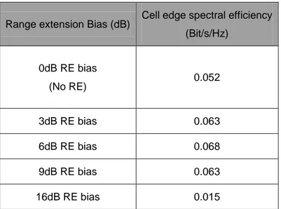
Range extension [29] is an approach in which an offset is added to the Pico cell RSS in order to increase its DL coverage footprint. Table 4-2 [26] provides data channel
performance evaluations for Hetnets with different RE bias, with full buffer traffic. It can be seen that a good balance between cell group average throughput and cell edge throughput is reached with 6-9 dB of range extension bias in this scenario, while a very large RE bias of 16dB does not provide good cell edge throughput. RE may be jointly designed with ICIC in Hetnets, which together can be regarded as one simple implementation of COMP. Thus high RE biases are not precluded in future hotspot deployments for the sake of load sharing and UL/DL coverage imbalance solution.
Table 4-2 Hetnets evaluation with different range extension bias
Even though range expansion significantly mitigates cross-tier interference in the UL, this comes at the expense of reducing the DL signal quality of those users in the expanded region. Such users may suffer from DL SINRs below 0 dB since they are connected to cells that do not provide the best DL RSS as shown in figure 4-3[27].
Range extension Bias (dB) Cell edge spectral efficiency
(Bit/s/Hz) 0dB RE bias (No RE) 0.052 3dB RE bias 0.063 6dB RE bias 0.068 9dB RE bias 0.063 16dB RE bias 0.015
36
4.3.2. Inter-cell interference coordination (ICIC)
The interference problems summarized in section 4.2.5 may significantly degrade the overall Hetnets performance, which requires the adoption of ICIC schemes to mitigate the
interference and optimize its operation. In such schemes, it should be taken into
consideration that the mitigation of inter-cell interference in the control channels UEs may lead to RLF under severe interference, and experience service outage due to the unreliable DL control channels. Moreover, it is essential that UEs are able to sense, detect, and report information to their servers concerning potential interfering cells being present in their neighborhood. Then, the UE serving cell in collaboration with the potential interferers will coordinate their resource allocation in terms of power, frequency, and time to enhance network capacity and mitigate user outages.
Hetnets cells‘ information messages need to be exchanged between Hetnets cells to achieve a reliable coordination between them. Macro cells are connected to LPNs through the X2 interface.The ICIC messages defined in Rel. 8 that can be exchanged via the X2 interface can be listed as follows [30]:
• Relative Narrowband Transmit Power (RNTP) Indicator: An indicator sent by a specific cell used to coordinate with the adjacent cells about transmission power threshold about specific PRBs in the DL transmissions. An adjacent cell can utilize the RNTP information in the scheduling of it is own terminals in which they are located on the cell-edge which is subjected to the interference from the adjacent cells who are willing to transmit with high power PRBs.
• Overload Indicator (OI): The OI indicator is an indicator to exchange the average
interference plus thermal noise power measurements for each PRB between different cells for UL transmissions. It would be possible for an adjacent eNB that received the OI to change its scheduling to reduce the interference for the eNB that issued the OI.
• High Interference Indicator (HII): An indicator used by a certain cell to notify the adjacent cells that one of its cell-edge users will be scheduled for UL transmission in the near future. The adjacent cells that received the HII indicator may sustain scheduling their own cell-edge users in the specified PRBs. The HII indicator is way to prevent the low SIR scenarios by avoiding scheduling of the cell-edge terminals on the same PRB and hence reducing the UL interference for cell-edge transmissions to the receiving eNB.
The ICIC techniques discussed above may not efficiently cover all the Hetnet interference scenarios discussed previously in section 4.2.5, as the control signaling in each sub-frame is more problematic as it spans the full cell bandwidth and therefore not subject to ICIC. Consequently, the technique of enhanced ICIC (E-ICIC) is introduced in Rel. 10, with 2 schemes; one for time domain and one for frequency domain. The E-ICIC in the time domain includes a new way for sub-frame alignment that the sub-frames of macro eNB and LPN eNB are aligned as in Figure 4-4[27]; their control and data channels overlap. One possible approach to accomplish ICIC here is to use ABSF to reduce the interference. When no interference coordination is used for range-expanded LPN users, they observe large DL interference from the macro-cell.
38
Macro cell and Pico cell sub-frames without any E-ICIC
In Hetnets, the handling of L1/L2 control signaling interference is not obtained traditionally. The deployment of range extension may cause low SINR from the Pico cell users in the extended regions. At this low SINR, this situation will make it hard to decode the L1/L2 control channels. To deal with this problem, specific methods of frequency domain E-ICIC schemes are adopted. The interference cancellation of signaling channels is performed by separating control signaling for the different cell layers where at least one component carrier in each cell layer is protected from interference from other cell layers by not sending
(PDCCH, PCFICH, PHICH) control signaling on the component carrier in question in the other cell layers as shown in figure 4-5 [22]. The macro eNB sends control signaling on component carrier f1 but not on component carrier f2, while the situation is the reverted in the LPN deployed within the macro cell. Since Rel.10 introduces cross-carrier scheduling, resources on f2 can be utilized for data transmission, scheduled by control signaling received on f1. This approach will create frequency reuse for the control signaling while still permitting terminals to utilize the full bandwidth and accordingly enabling the highest data rates.
40
5. LPN Deployment on 3GPP User Distribution
This Chapter presents an evaluation of how some important QoS parameters are affected in a deployment of LPNs in a system with different user distributions. Also discussed is how this deployment scheme will affect the overall performance of the system.
In real cellular systems, the user distribution is not homogeneous within a macro cell area, and the users always have the tendency to cluster around certain areas, such as shopping centers, airports, etc., thus forming so called spots. The number and location of hot-spots are highly impacted by the user‘s distribution scheme, and this scheme will frequently be changed when the users move around. In Hetnets, it is not necessarily so that the LPN will be deployed in the center of hot-spots, although operators probably will try to make this happen. Hence, the LPNs might be deployed in the vicinity of where users are clustered around hot-spots with different densities.
5.1. Simulation Metrics
In this report, several performance metrics have been identified to be used as a means to evaluate and compare all the studies similarly.
5.1.1. System Throughput
The system throughput was calculated by measuring the number of received bits during a simulation for time t seconds.
5.1.2. SINR
The SINR is the amount of useful signal in any transmission divided by the interference combined with noise, averaged over the simulation time t.
5.1.3. Interference
The interference is calculated by subtracting the power of useful signal from the total power, see equation (5-1), and averaged over time t:
5.1.4. Video Capacity
In this report, the video-telephony capacity has been defined as the load where 97% of the users receive at least X% of their packets within Y ms in UL and DL. The value X represents the FER limit which has been set to 3%, and the value Y represents tail latency which is the air interface delay from when the packet enters the PDCP layer from the transmission side until it leaves the PDCP layer on the receiving side [37]. A delay requirement of 150 ms has been defined as a default delay requirement. Core and transport delay constitutes 100 ms.