1
STRUCTURAL ANALYSIS OF A WASHING
MACHINE THROUGH ITS LOADING CASES.
REDESIGN OF THE TRIPOD AND THE FRONT COVER
Bachelor Degree Project in Mechanics Level 22.5 ECTS
Spring term 2011
Rocío González Zuheros Raimundo Abril López Pablo Huertas Molina
Supervisor: Alexander Eklind Examiner: Thomas Carlberger
2
Abstract
This project thesis is developed in collaboration with the mechanical department at University of Skövde, and it is focused in the determination of different loading cases and the application of their results to the optimization of two parts of a washing machine.
The first step in this report is to obtain a numerical model of a washing machine. It includes the assembly in a mechanical software program (Abaqus), and the assignment of the specific boundary conditions and material properties for the problem. Simulation parameters such as mesh size; types of elements, and number of iterations used in the calculations will also be decided.
A study of the different loading cases is carried out with the intention of having a general view of the problem and selecting four specific cases for its application to the reconstruction of the aimed parts (tripod and front cover). This study includes the calculation of the worst relative angle between the tripod and the resultant force for two opposite loads inside the drum. This angle results to be 35º between the arm and the direction of the resultant force.
Through the application of these different loading conditions to this model, the mechanical behaviour of the parts will be obtained and this information will be used in the reconstruction. By mechanical behaviour it is meant to know the maximum level of stress (tension, compression and shear), and deformation (displacement and strain).
Once it is well known which are the most suffering points of the tripod and in the front cover, several different new shapes are created. The parameters considered in this reconstruction were the decrease of volume, the reduction of the level of stress and the deformations. Two of these shapes are chosen and tested in the numerical model, as a checkout.
Finally all these results are presented to the University of Skövde for possible future use.
3
Certificate of authenticity
Submitted by Rocío González Zuheros, Raimundo Abril López and Pablo Huertas Molina to University of Skövde as a Bachelor Degree Project at the School of Technology and Society.
We certify that all material in this Bachelor Degree project which is not our own work has been identified.
____________________________ ___________________________ __________________________ Rocío González Zuheros Raimundo Abril López Pablo Huertas Molina
4
Table of contents
Abstract ... 2 Certificate of authenticity ... 3 Table of contents ... 4 Table of figures ... 7 1. Introduction ... 111.1. Purpose with the thesis ... 11
1.2. General research in washing machines ... 12
1.2.1. History ... 13 1.2.2. Washing process ... 13 1.2.3. Fabrication process ... 14 1.2.4. Latest improvements ... 14 1.3. Reconstruction ... 15 1.3.1. Design concept ... 15 1.3.1.1. Design stages... 15
1.3.1.2. Considerations or design factors ... 16
1.3.2. Criteria for the parts redesign ... 18
1.3.2.1. Costs ... 18
1.3.2.2. Mechanical behavior improvement ... 19
1.3.2.3. Environmentally friendly solution ... 19
1.3.3. Criterion for failure estimation ... 19
2. Implementation... 21
2.1. Working with FEM ... 21
2.1.1. History ... 21
2.1.2. Applications... 21
2.1.3. Working flow with FEM ... 22
2.2. Assembly in Abaqus ... 24
2.2.1. Preparation of the model ... 24
2.2.2. Simulation process in Abaqus ... 24
2.2.2.1. Part ... 24
2.2.2.2. Material ... 30
2.2.2.3. Interaction... 31
2.2.2.4. Analysis ... 33
5
2.3. Mesh ... 33
2.3.1. Tetrahedrical elements ... 34
2.3.2. Shell elements... 36
2.3.3. Results for the study of convergence ... 37
2.4. Loading cases ... 39
2.4.1. Parameters ... 39
2.4.1.1. Rotational speed and unbalance ... 39
2.4.1.2. Load ... 40
2.4.1.3. Number of loads ... 40
2.4.1.4. Area ... 41
2.4.2. Choice of simulations ... 42
3. Results ... 43
3.1. Simulation 1. Single load ... 43
3.2. Simulation 2. Cylinder loaded with two opposite loads ... 45
3.3. Simulation 3. Cylinder loaded in 3 regions ... 47
3.3.1. Mechanical behaviour of the tripod ... 49
3.3.1.1. Connection with the cylinder ... 51
3.3.1.2. Connection with the shaft ... 52
3.3.1.3. Arm A ... 53
3.3.1.4. Arms B and C ... 54
3.3.2. Mechanical behaviour of the front cover ... 55
3.3.2.1. Connection with the cylinder ... 56
3.3.2.2. Section curvature ... 57
3.3.3. Study of stiffness ... 57
3.3.3.1. Study of rigidity for the tripod ... 58
3.3.3.2. Study of rigidity for the front cover ... 60
4. Tripod reconstruction ... 63
4.1. Generating concepts ... 63
4.1.1. Safety factor ... 64
4.1.2. Main concepts ... 64
4.1.3. Combining and evaluating concepts ... 65
4.2. Optimization of solution 1 ... 71
4.2.1. Boundary conditions and mesh for solution 1 ... 73
4.3. Optimization of solution 2 ... 74
4.3.1. Boundary conditions and mesh for solution 2 ... 75
6
5.1. Generating concepts ... 77
5.1.1. Safety factor ... 77
5.1.2. Study dimensions ... 77
5.1.3. Main Concepts ... 78
5.1.4. Combining and Evaluating Concepts ... 81
5.2. Optimization of solution 1 ... 82
5.2.1. Mesh and boundary conditions for solution 1 ... 83
5.3. Optimization of solution 2 ... 84
5.3.1. Mesh and boundary conditions for solution 2 ... 85
6. Loading cases for reconstruction ... 87
6.1. Calculation of the worst angle for two loads ... 87
6.1.1. Introduction and strategy definition ... 87
6.1.2. Strategy ... 87
6.1.3. Studied region ... 88
6.1.4. Repetitive simulation of the model ... 89
6.1.5. Conclusions ... 90
6.2. Calculation of loading cases for re-construction ... 90
6.2.1. Analytical representation ... 91
6.2.2. Definition of the loading cases ... 93
6.2.2.1. Loading case 1... 93
6.2.2.2. Simulating the worst case for two loads. Loading case 2 ... 93
6.2.2.3. Loading case 3 ... 94
6.2.2.4. Loading case 4 ... 94
6.2.2.5. Loading cases ... 94
7. Numerical validation of solutions ... 96
7.1. Tripod ... 96
7.2. Front cover ... 102
7
Table of figures
Chapter 1
Figure 1.1. Main components in the assembly ... 11
Figure 1.2. Original front cover that will be reconstructed ... 12
Figure 1.3. Original tripod that will be reconstructed ... 12
Figure 1.4. Design factors ... 17
Figure 1.5. Redesign methodology tree ... 18
Chapter 2 Figure 2.1. Workflow when working with FEM ... 23
Figure 2.2. Current design of the tripod ... 25
Figure 2.3. Strength-Cost of different materials [8] ... 26
Figure 2.4. Comparison between sand casting and die-casting [4] ... 27
Figure 2.5. Inner cylinder, front cover and rubber [11] ... 28
Figure 2.6. Manufacturing process of stainless steel ... 30
Table 2.1. Properties of materials used in the assembly [2] ... 31
Figure 2.7. Cylinder with highlighted constraints showing rear cover and front cover unions. ... 32
Figure 2.8. Tripod with highlighted constraints ... 32
Figure 2.9. Interaction applied to the paddle. ... 32
Figure 2.10. Front cover constrained ... 33
Figure 2.11. Boundary conditions in axle ... 33
Figure 2.12. Tetrahedron with degrees of freedom and integration point indicated [3] ... 34
Figure 2.13. Mesh for the axle. 12800 tetrahedrical elements. ... 35
Figure 2.14. Mesh for one of the paddles. 11700 tetrahedrical elements ... 35
Figure 2.15. Mesh for the tripod. 52000 tetrahedrical elements. ... 35
Figure 2.16. Degrees of freedom for a shell element and integration points ... 36
Figure 2.17. Mesh for the cylinder. 30900 shell elements ... 36
Figure 2.18. Mesh for the rear cover. 1880 shell elements ... 37
Figure 2.19. Mesh for the front cover. 8350 shell elements. ... 37
Figure 2.20. Convergence study for the tripod using von Mises stress ... 38
Figure 2.21. Convergence study for the tripod using von Mises stress ... 38
Figure 2.22. Cylinder submitted to rotational speed ... 39
Figure 2.23. Model loaded in a single region ... 41
Figure 2.24. Model loaded in 2 regions ... 41
Figure 2.25. Model loaded in 3 regions ... 41
8 Chapter 3
Figure 3.1. Explicative sketch for simulation 1 ... 43
Figure 3.2. von Mises average stress in the cylinder with applied loads ... 44
Figure 3.3. Cylinder displacement in mm ... 44
Figure 3.4. Tripod von Mises stress distribution ... 44
Figure 3.5. Explicative figure for simulation 2 ... 45
Figure 3.6. von Mises stress in the inner side of the cylinder, paddle, front and rear covers. ... 46
Figure 3.7. von Mises stress distribution in the tripod. ... 47
Figure 3.8. Simulation 3 explaining sketch ... 47
Figure 3.9. Tripod with von Mises stress distribution ... 48
Figure 3.10. Front cover averaged stresses according to von Mises law ... 48
Figure 3.11. von Mises average stress in the cylinder viewed from its outer side. ... 49
Figure 3.12. Equivalent force due to the unbalance and its effect over one arm of the tripod... 50
Table 3.1. Effects on the arm ... 51
Figure 3.13. von Mises equivalent stress in the connection with the cylinder ... 52
Figure 3.14. von Mises average stress in connection with the shaft of the tripod ... 52
Figure 3.15. Bending of the arm. von Mises stress distribution ... 53
Figure 3.16. Combination of bending and tension ... 54
Figure 3.17. Deformation due to the bending ... 54
Figure 3.18. General view of torsion, shear and bending in the tripod ... 55
Table 3.2. Effects on the front cover ... 56
Figure 3.19. von Mises average stresses in the connection with the cylinder ... 57
Figure 3.20. von Mises average stresses in curvature change ... 57
Figure 3.21. von Mises average stresses in the connection tripod-cylinder ... 59
Figure 3.22. von Mises average stress in front cover and cylinder in simulation 1 ... 61
Figure 3.23. von Mises average stress in front cover and cylinder in simulation 2. ... 62
Table 3.4. Explicative chart for the study of stiffness of the front cover. ... 62
Chapter 4 Figure 4.1. Main functions of the part ... 63
Table 4.1. Main objectives of the tripod’s redesign ... 64
Table 4.2. Concepts in the Redesign ... 65
Table 4.3. Solutions generation ... 65
Figure 4.2. Concept 1 ... 68
9 Figure 4.4. Concept 3 ... 69 Figure 4.5. Concept 4 ... 70 Figure 4.6. Concept 5 ... 70 Figure 4.7. Concept 6 ... 71 Figure 4.8. Solution 1 ... 72
Figure 4.9. Connection with the shaft of Solution 1 ... 72
Figure 4.10. Connection with the cylinder of Solution 1 ... 73
Figure 4.11. Mesh for solution 1 in tripod reconstruction. 52200 tetrahedrical elements ... 73
Figure 4.12. General view of Solution 2 ... 74
Figure 4.13. Reinforcements and connection with the shaft of Solution 2... 75
Figure 4.14. Connections with the cylinder of Solution 2 ... 75
Figure 4.15. Interactions for solution 2 in the tripod reconstruction ... 75
Figure 4.16. Mesh for solution 1 in tripod reconstruction 54800 tetrahedrical elements ... 76
Chapter 5 Table 5.1. Re-design concepts for the front cover ... 78
Figure 5.1. Concept 1 ... 79
Figure 5.2. Concept 2 ... 79
Figure 5.3. Concept 3 ... 80
Figure 5.4. Concept 4 ... 81
Figure 5.5. Concept 5 ... 81
Table 5.2. Solutions generation ... 81
Figure 5.6. Rendered image of solution 1 for the front cover ... 83
Figure 5.7. Mesh for solution 1 in front cover reconstruction. 31800 shell elements ... 84
Figure 5.8. Rendered imaged of solution 2 for the front cover ... 85
Figure 5.9. Mesh for solution 2 in front cover reconstruction. 28400 shell elements ... 86
Chapter 6 Figure 6.1. Explicative sketch of studied variable ... 87
Figure 6.2. Angles studied in worst case calculation ... 88
Table 6.1. Angles studied in calculation of worst case. ... 89
Figure 6.3. Average von Mises stress for the front cover in worst case study ... 89
Figure 6.4. Average von Mises stress for the tripod in worst case study ... 90
Table 6.2. Higher values for von Mises stress in the simulation performed ... 90
Figure 6.5. Mass distribution ... 92
Figure 6.6. Masses-Relative angle ... 93
Table 6.3. Loading cases for the re-construction ... 94
10 Chapter 7
Table 7.1. Numerical Validation. Displacement ... 96
Figure 7.1. Comparison of the maximum displacement ... 97
Figure 7.2. Points for measurements in the tripod reconstruction ... 97
Figure 7.3. Stress in Loading Case 1 ... 98
Figure 7.4. Stresses in Loading Case 2 ... 98
Figure 7.5. Stresses in Loading Case 3 ... 98
Figure 7.6. Stresses in Loading Case 4 ... 99
Table 7.2. Numerical validation of Solution 1. Safety factor ... 99
Figure 7.7. Margin of benefits depending on Steel prices ... 100
Figure 7.8. von Mises stress distribution in the rear cover in Solution 2 ... 101
Figure 7.9. Averaged von Mises stress distribution in the cylinder in Solution 2 ... 101
Table 7.3. Numerical validation. Displacement ... 102
Figure 7.10. Deformation diagram for the three parts ... 102
Figure 7.11 Points for the maximum von Mises stresses in the front cover reconstruction ... 103
Table 7.4. Numerical validation. von Mises max. stress ... 103
Figure 7.12. Maximum von Mises stress for the three parts ... 104
Table 7.5. Numerial validation. Safety factor ... 104
Figure 7.13. Safety factor for the three parts ... 104
Table 7.6. Numerial validation. Volume ... 105
11
1.
Introduction
Washing machines are commonly used in almost every home worldwide. These appliances make it easy to clean clothing; a process that time ago was heavy and unpleasant. The performance of these machines is based on the rotation of the clothes inside a cylinder while they are mixed with water and some kind of cleaning powder or soap.
It is not hard to imagine that the load of these clothes, when they are soaked in water can create big reaction forces in the cylinder when they are rotating. This situation makes it very important to calculate accurately and for safety side the mechanical characteristics of the cylinder mentioned and the tripod that transmits the turning forces to the cylinder.
The University of Skövde has created this bachelor thesis project where it is intended to determine the critical load and position in which the reaction forces applied to these parts are maximal, in order to avoid malfunctioning in working washing machines. The possibility of creating new shapes for that tripod and front cover is also studied, so that the reaction forces have a better distribution and the risk of damage to the parts is smaller.
A group of students from the University of Skövde with the aim of creating successful results that can be used in future designs carries out the project.
1.1. Purpose with the thesis
The main objective with this project is to perform a research on the loading cases applied to a washing machine and to optimize the tripod and the front cover.
12
In figure 1.1 it is shown the main components of the washing machine. From these parts we have chosen the tripod (figure 1.3) and the front cover (figure 1.2) to be studied and redesigned as it was suggested by ASKO due to the recent modification of the cylinder.
Figure 1.2. Original front cover that will be reconstructed
Figure 1.3. Original tripod that will be reconstructed
Different approximations to the problem will be considered in order to create solutions that can be compared and judged to establish which is the best.
In addition, new solutions will be suggested. These solutions might solve an existing problem or might just work fine for future developments of washing machines.
The conclusions of this work are presented in this report.
1.2. General research in washing machines
In this chapter a brief review on the historical background of washing machines is performed. This will include the history of this device, the process it follows in its functioning, how it is produced and how it evolved through time.
13
1.2.1. History
In ancient times people had to take a pack and carry their clothes over to the creek and hit them against rocks to get rid of the stains and filth. But with the advancements in technology, washing machines have now made this cumbersome chore a simple task, which can be done at the touch of a button. The washing machine has become more of a necessity than a luxury.
In the late 1800s, companies started producing hand-operated machines that used paddles or dollies. Then the revolving drum came, which was shortly followed by a revolving drum with reversing action. In the early 1900s, with the advent of small electric motors, the washing machine entered the electric age. Washing machines nowadays have advanced to such a level that they basically do everything themselves. All the operator has to do is put the clothes in the washer, select the temperature and wash settings and go about their business. Contemporary washing machines are available in two main configurations, top- loaded and front-loaded:
The top loaded design places the clothes in a vertically mounted cylinder, with an agitator in the centre of the bottom of the cylinder. Clothes are loaded through the top of the machine, which is covered with a hinged door.
The front loaded design instead mounts the cylinder horizontally. Loading is done through a glass door at the front of the machine. Agitation is supplied by the back-and-forth rotation of the cylinder, and by gravity. The clothes are lifted up by paddles in the drum and then dropped.
All washing machines use three different sources of energy, mechanical, thermal and chemical energy. Thus, mechanical energy is imparted to the clothes load by the rotation of the agitator in the top loaders, or by the tumbling action of the drum, in the front loaders. The temperature of the wash bath supplies thermal energy, while the detergent and other laundry chemicals supply chemical action.
1.2.2. Washing process
Washing machines get clothing clean by plunging the clothes through the water and detergent mixture. It is the motion that really helps to loosen dirt. The washing is done by rotation of the drum causing the mixture of laundry and detergent. The movement of the drum is caused by an electric motor.
The timer controls each and every part of the washing cycle. The timer controls various other switches in order to control several other functions. This is also the one that decides on the correct amount of electricity to be sent to each section of the machine at the right time.
The operation of a washing machine is mainly split into four steps: 1. Pre-washing, 2. Washing and rinsing, and 3. Spinning.
14
1. The prewashing operation, like the washing, is a collection of water and detergent, a cyclical movement of the drum with successive investments of rotation, and a simultaneous warming of the water.
2. The washing process consists of successive rinses provoked by cyclic rotation investments. Each of these cycles ends with emptying the machine. The spin is to draw the water from the clothes washed, so during this time the machine will also be an emptied. The washer has two tubs, the inner tub with hundreds of holes in it and the outer tub which holds the water. Once the washing is done, the machine automatically switches to the spin mode, depending on what program that the user has set.
3. During the spin cycle the inner tub spins, forcing the water out through the holes to the stationary outer tub. When the clothes are clean the drum spins at thousands of RPMs using centrifugal force to squeeze water out of the fabric. When the machine has run through its cycle the clothes are left clean and just a bit damp (instead of soaking wet).
1.2.3. Fabrication process
Many parts of a washing machine are manufactured from sheet steel, usually coated with zinc to improve corrosion resistance. The spin tub is made of stainless steel.
Most sheet metal parts are formed by a machine that presses a piece of sheet metal between two halves of a mold (die). Because metal in parts shaped by only one step tends to wrinkle, crack, or tear, multiple steps are generally used to form each component.
The tub sub-assembly is manufactured automatically. After being rolled into a drum shape, the side is welded. The weld is then smoothed out and the drum is placed on an expander, which stretches the tub applying high pressure into its final shape.
1.2.4. Latest improvements
The current improvement is the tendency of going in the way of removing noisy and vibrating parts such as the belts. To achieve this motors are improved and a new transmission system called direct drive is implemented in most new models. European Union environmental requirements force the manufacturers to increase their production of front-loaded washing machines against top-loaded washing machines. This is because front-loaded washing machines require less water than top-loaded ones for a similar performance. Most of the energy use of a washing machine is for the heating of water in a deposit with an electrical resistance before it goes into the cylinder. These front-loaded washing machines can also perform higher spin speeds, what makes them more efficient, because it reduces the energy needed in the drying process. There are more ways of
15
improving the efficiency of a washing machine but in this thesis only the advantage of the high spinning speed will be studied.
Due to all this it is necessary to research stresses to make it possible to use higher spin speeds in order to reduce energy consumption as explained in the previous paragraph.
1.3. Reconstruction
It is necessary for the better understanding of this thesis to get a general knowledge of the process followed in the reconstruction of the two parts that are an objective. This reconstruction will be carried out once the mechanical behaviour of each part is known, so we can solve the problems in the current models and create better ones.
In this section, the process followed to complete the reconstruction of the two parts considered in this project will be explained. Concepts such as design in mechanical engineering or the stages in a redesign will be profoundly reviewed. Several different design factors are considered in this re-construction, as will be explained later. A research over joints is performed and it is concluded that they will not be changed, so a superficial explanation of most common joint unions will be explained here, while the rest of the design concepts will be reviewed during its modification.
1.3.1. Design concept
Mechanical design is the design of objects and systems of mechanical nature, such as parts, structures, mechanisms, machines, devices, and tools. Most of the time mechanical design uses mathematics, material science, and mechanical science applied to engineering. Mechanical design requires big amplitude study that includes all disciplines in engineering, including thermal and fluid sciences. In this case, material science, mechanical science and the finite element method will be used in the reconstruction of the parts.
1.3.1.1. Design stages
Often the total design process is described from start to finish. It starts with the identification of a need and the definition of the problem, followed by decision on a design process. Then the design is tested for evaluation and presentation. Identification of need and problem definition
Often, but not always, the design starts when an engineer realizes that something needs to be fixed and decides to do something about it. Generally that need is not something evident; it requires a deep study to find the failure.
Once the problem is defined and a group of specifications is obtained, the next step in the design process is the synthesis of an optimal solution. This synthesis
16
will not be possible to determine if it will fit the specifications before analysis and optimization. This analysis could reveal that the system is not optimal. If design does not fulfill the specifications in one of the tryouts or in both, the synthesis procedure should start again.
Evaluation and presentation
Evaluation is a significant phase of the total design process, because it is a definite demonstration that a design is correct and generally includes experiments with a model in the laboratory. This is the point when the designer observes if the design actually satisfies the needs.
Communication to other people about the design is the final and vital step in the design process. Making other people understand the idea and its realization is a key point, since it usually leads to the physical realization of the parts, the structure or the system.
1.3.1.2. Considerations or design factors
Sometimes, the strength of an element is very important to determine the geometric configurations and dimensions that this element will have. In that case it can be said that strength is an important design factor.
The expression design factor signifies any characteristic or consideration that influences the design of some element or, maybe, the whole system. Generally several factors have to be taken into account in case of a determined design. On some other occasions one of these factors will be critical and, if its conditions are satisfying, it will not be necessary to consider the rest of the factors. In this thesis project the following will be taken into account:
Strength Shape Size Flexibility Stiffness Joints
17 Figure 1.4. Design factors
Research on joints
Two steel elements come together to work together, and they are connected with each other, with one or more of the four joining methods: rivets, bolts, welds or pins.
For many years the riveted joints were the generally accepted method for connecting steel parts. However, rivets have been replaced by welding and by high strength bolts, because these elements achieve the same stiffness as rivets, but at lower costs and with shorter installation times.
Materials
Nowadays there are a great many materials each one with its own characteristics, applications, advantages and limitations. The following is a list of the general kind of materials used now in the manufacture either individually or combined. These are four kinds. First, there are ferrous materials, like carbon steel, alloys, stainless steel, and machinery steel. Secondly alloys and non-ferrous materials are aluminum, magnesium, copper, nickel, titanium, super alloys, refractory materials, beryllium, and zirconium. Thirdly among ceramics it is possible to find glass, graphite, and diamond. Finally, composite materials are reinforced plastics, composites with metallic or ceramic matrix.
Design with new materials
Materials reinforced with carbon and glass fibers are commonly used in civil and marine constructions, as well as in sports goods. Plastic materials are considered in this thesis project in the redesign of the tripod.
18
1.3.2. Criteria for the parts redesign
Before starting with the redesign of the tripod and the front cover, the criteria that will be used to estimate the validity of a solution must be established.
Figure 1.5. Redesign methodology tree 1.3.2.1. Costs
Costs are one of the main objectives that this project must cover, due to the fact that this is one of the most important factors that condition a plan for a factory. In case of decision, costs will have the largest influence over the rest of the options. But, how is it possible to reduce costs?
Cost reduction can be made in the choice of materials used. Research over the most important materials available must be done in order to ensure that both aluminium and stainless steel is the best option for these parts as it is currently used.
By reducing the volume of material used an improvement in costs can be found. Not always will reducing the volume of material mean a loss of mechanical properties.
Manufacturing processes can also reduce costs. Every different material requires a different process, so not only the price of the raw material has to be considered. For instance, to study if a solution using steel and sand casting can be suitable. Manufacturing costs can be split into casting, machining, fabrication, welding, bolting and gluing.
Variables Objectives Step Optimization Cost reducement Material Geometry Manufacturing Process Mechanical Behavior Improvement Maximum values of Stress Deformation Environmentally Friendly Solution
19
However, the mechanical behaviour has to be considered because a really cheap and suitable material cannot satisfy the mechanical requirements or it is possible that the mechanical properties obtained from the manufacturing process do not achieve the necessary minimum.
1.3.2.2. Mechanical behavior improvement
Other important objectives to cover can be improving both the tripod and the front cover in order to avoid possible mechanical failures. Studying the actual load and stress distribution and trying to reduce the maximum values or to include stress-reducing features in the models can achieve this objective. A profound research in what kind of stresses and the maximum values of them has to be performed.
The deformation can also be considered taking into account the maximum value and try to reduce it increasing the rigidity of the assembly or whatever method used.
Not only the tripod or the front cover can be improved with these modifications, but the stress distribution in the cylinder can also be modified. In fact, a better solution for it can be found.
1.3.2.3. Environmentally friendly solution
By using recyclable materials, by choosing the least energy waster process, or by reducing the waste of water during the washing process, a better solution for the environment can be found. For instance, in the case of reducing the energy used in the manufacturing process, the direct costs are also decreasing.
1.3.3. Criterion for failure estimation
The criterion that will be used for the estimation of the scalar value of an element’s stress tensor will be the von Mises Equivalent Stress. It is one of the best criteria to predict the failure for ductile materials due to the fact that it uses the distortion energy as a criterion. This means that the value of one of the principal components can reach the yielding strength and the material is no plasticizing. Moreover, this criterion predicts the failure under pure shear for and the reality shows that it is produced for [10], so it is a good criterion.
The mathematical expression for this criterion can be obtained by equalling the distortion energy to the energy necessary to yield a test tube. In this case it is expressed in principal components.
21
2.
Implementation
In this chapter most of the technical aspects of the parts and materials used in this thesis, and the basic settings used on the simulations will be described. Firstly, a review on the Finite Element Method (FEM) will be performed so that the process followed in every simulation can be explained.
2.1. Working with FEM
This section will explain in a brief way what the process to follow is when working with FEM method, as it is the case for this project.
2.1.1. History
The origin of the finite element method (FEM) is the need to solve complex elasticity and to make a structural analysis in mechanical engineering. The development can be set back in the 1940s when first approaches to the idea were started. Although the approaches of the pioneers were different, they shared one characteristic: the mesh of a continuous domain into smaller sub-domains called elements. These elements were joined together in points called nodes.
2.1.2. Applications
Almost all applications in the field of mechanical engineering discipline use FEM in the development and design of their products. FEM is a great tool when producing stiffness and strength visualizations and also when optimizing weight, materials and costs.
FEM allows the visualization of structures submitted to loads and shows stresses and their distribution. Many different settings can be modified in FEM software in order to obtain the most realistic models. The user, who can manage both computational time and accuracy required depending on the application, chooses the level of detail.
The biggest inconvenience of this method is the blind faith in the results provided by the software. Since it is the user that sets the configuration, it is necessary to be critical with the results and make an intensive discussion before accepting them as valid. The conclusion is that FEM is a powerful tool that should be used by trained professionals.
FEM has improved the design and the design methodology in many industrial applications, and has reduced the time from idea to production line.
22
2.1.3. Working flow with FEM
The flow of work used in each simulation can be seen in figure 2.1. The steps are the following:
1. Creation (reception) of 3D model
2. Preparation of the model before taking it into FEM software such as elimination of bad geometry, simplification of unnecessary parts and improvement of contact regions
3. Basic inputs in Abaqus. This information will allow the model to work properly during simulation and will define the behavior of the parts during the analysis
4. FEM inputs. These parameters will control the computational time and the accuracy of results in the simulation. A special analysis of factors is performed in order to define them.
5. Simulation is carried out by the software
6. Results obtained need to be evaluated and judged as good or bad before presenting them in the report.
23 Figure 2.1. Workflow when working with FEM
It is important to be very accurate and methodical during the inputs phases, both those affecting the model and the calculation method. These decisions will define the validity of the result and its possible utility in real production.
3D model
(received from ASKO)Model
preparation
Basic inputs in Abaqus Material Boundary conditions Sections InteractionsFEM inputs
Mesh and convergence study Steps (attempts)
Job
Loading case
Simulation
Analysis of results
24
2.2. Assembly in Abaqus
2.2.1. Preparation of the model
The first stage of this thesis project is to prepare the numerical model that will be tested using the software program Abaqus. This assembly was received directly from the ASKO Appliance as a CAD model that was later modified in order to meet the requirements that Abaqus sets to work properly.
It was found that the best way to import files from other programs into Abaqus was using the file extension Standard ACIS Text (.sat).
In this first version all the parts were solid, but in order to obtain manageable computational times and to avoid problems in the mesh-creating algorithm some parts such as the front cover, the rear cover, and the cylinder are assigned to be shells. These parts can be simplified as shells because one dimension, specifically thickness, is considerably smaller than the others two. Also, these parts contain small features i.e. the holes in the cylinder that make it impossible to create a solid mesh with a reasonable mesh size and with manageable computational times.
The next step is to create the model in Abaqus that will simulate the real working washing machine, always remembering the limitations of the FEM method. This model will be assigned certain parts, materials, boundary conditions, analysis configuration and interaction between its parts, in order to make it work as it is intended.
2.2.2. Simulation process in Abaqus
In this section every one of the actions will be explained step by step and with a high level of detail made in Abaqus, from the beginning to the start of the simulation. With this the intention is to clarify every aspect of the simulation, so the results can be interpreted in the correct way.
2.2.2.1. Part
This model is composed of 11 different parts: 3 screws, 3 paddles, 1 cylinder with a 0.48 m. diameter, 1 rear cover with the same diameter as the cylinder, 1 front cover with an outer diameter of 0.48 m. and an inner diameter of 0.2m, 1 tripod with an outer diameter of 0.45 m. and 1 axle. These 11 parts are assembled together to create the model that will later be worked in Abaqus. The screws are not mounted in the final model because they are substituted by their effect, i.e. the elimination of the relative displacement between the regions affected by them. This is achieved by using the Abaqus function called “tie” connection.
25 Tripod
In this chapter the part tripod will be analysed, focusing on the geometry, the material used and its manufacturing process. The main task of this tripod is to connect the shaft with the cylinder, and to transmit the torque between them, so this is one of the most important structural components of a washing machine. To understand how the tripod is loaded and how the stresses change depending on the loads applied will show possible solutions for the future reshaping.
Current design
The tripod consists of 3 arms, 3 connections with the cylinder, and 1 connection with the shaft. These regions can be appreciated in figure 2.2 and they will focus the attention of this redesign.
Figure 2.2. Current design of the tripod
These regions have different characteristics, geometries, and functions.
- The connection with the shaft is a robust cylinder with stiffeners to keep its relative position with the rest of the part.
- The main characteristic of the arm is its section, due to the fact that it must be chosen depending on the kind of stresses that appear under working conditions explained before.
- The connections with the cylinder have two main features, the first one is the surface in contact with the cylinder, and the second one is the mass where the screw will be placed.
26 Material and manufacturing process
The material used for the production of this part is aluminium whose properties have been described in the materials chapter. Despite the fact that this material is lighter than steel, the manufacturing and production costs combined with the level of stresses in this part make it possible to think about other materials such as steel or plastics. In figure 2.3 it is possible to realize the differences in costs between the different materials.
Figure 2.3. Strength-Cost of different materials [8]
The volume of the actual model is 348000 mm3 and weighs 0.95 kg, so it is
possible to obtain a cost per unit taking into account only the raw material. The cost per kg for the aluminium is 2.62 €, so the cost per unit is 2.47€.
The manufacturing process for the aluminium requires a huge volume of production in order to obtain good rates of benefit. This process is called die-casting and consists of the injection, under high pressure and with high velocity, of molten metal into a split metal die. Aluminium is molten in a “cold-chamber”. The main advantage of this process is the high rate of production that can be achieved, and the high accuracy both for the smooth surfaces and the details. The main inconvenient is the complicated and expensive die that it is necessary to use and usually it is better to use cheaper dies and to finish the surfaces by tooling. The rate of production where tooling can be justified corresponds to the interval of 5000 to 10000 pieces, but for a large amount of parts the die casting process is definitely the least expensive.
Moreover, the die-casting can only be used when the mechanical properties are required to be the greatest. Die-casting can be compared with another similar process used in iron casting, sand casting. Sand-casting is cheaper in small sized batches because of its low setup costs, but when the batch is large, die-casting is
27
much cheaper because of its running costs. The production of parts is faster in die-casting because sand-casting requires a complicated process of preparation of the sand and manipulation of models.
The relation between sand casting and die casting processes and their prices per unit can be seen in Figure 2.4.
Figure 2.4. Comparison between sand casting and die-casting [4]
Since these considerations are taken into account, the design of the new parts is limited so that they can be manufactured in accordance to the processes mentioned. These limitations affect parameters such as radius, thickness and angles at drafts [4].
Front cover
In front-loaded washing machines, the cylinder is arranged horizontally and it is open from one of its bases, which connects to the door. The open base of the cylinder, called front cover, is designed with a large hole to allow entry and exit of laundry in the washer. The material used in its manufacture is stainless steel, and its functions are:
To enable input and output of clothing, connecting the cylinder to the outer casing of the machine where the door is.
To form a container where the clothes are placed.
To prevent clothes from falling out from the cylinder. The cylinder, the rubber and the door make it possible to create a closed container when the machine is working.
Specifically, the design of this part is a metal ring that connects its outer edge with the cylinder through bending, and the inner edge is free (see shape shown
10 100 1000 10000 100 1000 10000 100000 1000000 Cos t p er u nit Batch elements
Sand-casting // Die-casting costs
Sand-Casting Die-casting
28
in Figure 2.5) to make it easier to close the container with the door and the rubber. The rubber goes between the external drum and the door and allows the drum to bounce around without any clothes escaping.
Figure 2.5. Inner cylinder, front cover and rubber [11]
To consider a redesign of this piece, the first step is to study the stresses, which it is subjected to, and the strains that they cause, as explained in results chapter. The redesign is based primarily on the improvement of this situation, i.e. to decrease stress and reduce displacement on the piece. But also, the volume or size of the piece is taken into account in order to reduce the amount of material used in the manufacture, which will lead to economical savings and which should always be present in any study.
The actual design has a volume of 70400 mm3.
Material and Manufacturing Process
The design of a manufactured part is heavily dependent on the material and process by which it is made. For example, an aluminium die cast part and a steel sheet metal part would be designed entirely differently even though they both serve an identical function.
The front cover is made of stainless steel 18:9 (18 % chromium and 9 % nickel), as mentioned in material´s chapter, where its properties are shown.
There are many types of stainless steel in accordance with the characteristics that are wanted to get into the steel. Stainless steel resistance to corrosion and staining, low maintenance, and familiar appearance make it an ideal material for many applications.
Stainless steel is used where both the properties of steel and resistance to corrosion are required. Stainless steel differs from carbon steel by the amount of chromium present. Unprotected carbon steel corrodes readily when exposed to air and moisture. This iron oxide film (the corrosion) is active and accelerates corrosion by forming more iron oxide. Stainless steels contain sufficient chromium to form a passive film of chromium oxide, which prevents further
29
surface corrosion and blocks corrosion from spreading into the metal's internal structure.
The chromium forms a passivation layer of chromium oxide when exposed to oxygen. The layer is too thin to be visible, and the metal remains lustrous. The layer is impervious to water and air, protecting the metal beneath. Also, this layer quickly reforms when the surface is scratched. This phenomenon is called passivation and is seen in other metals, such as aluminium and titanium. Passivation only occurs if the proportion of chromium is high enough.
Furthermore, stainless steel is 100% recyclable. An average stainless steel object is composed of about 60% recycled material of which approximately 40% originates from end-of-life products and about 60% comes from manufacturing processes [12].
For all these reasons, stainless steel is used in the cylinders of washing machines and offers numerous advantages to its users; beyond the high resistance to water, soaps, detergents, etc., stainless steel ensures a surface smooth and free of lashings and cutting, avoiding the deterioration of the clothes in the washing process, caused by irregular surfaces. It also prevents damage of zips, coins, buttons, keys and objects such as these, at high speed on the machine, and would be fatal in the cylinders made of coated materials.
Despite all this, in the next chapter will be discussed the possibility of changing the material for another with better properties, better results or cheaper.
The manufacture of stainless steel involves a series of processes shown in figure 2.6. To make stainless steel, the raw materials iron ore, chromium, silicon, nickel, etc., are melted together in an electric furnace. This step usually involves 8 to 12 hours of intense heat. When the melting is finished, the molten steel is cast into semi-finished forms. These include blooms (rectangular shapes), billets (round or square shapes of 3.8 centimeters in thickness), slabs, rods, and tube rounds. Then it is cast into solid form. After various forming steps, the steel is heat treated and then cleaned and polished to give it the desired finish. Next, it is packaged and sent to manufacturers, who weld and join the steel to produce the desired shapes.
30
Figure 2.6. Manufacturing process of stainless steel
2.2.2.2. Material
The materials used in this assembly will be obtained both from the www.asko.com [1] webpage and from the inscriptions in the casting process or injected modelling in the parts. Every material in this project is considered to be homogeneous and isotropic.
Stainless Steel 18:9
Stainless Steel 18:9 is used in the shell parts which are the cylinder, the front and the rear cover and its properties are defined in the material’s table from its American standard AISI 302.
Aluminium 380
The properties considered for the tripod would be those corresponding to aluminium melted and shaped in die-casting. This special alloy 380 is based on aluminium with 9% of silicon and 3% of copper, and it is the most common and often recommended alloy used in die-casting.
PP20T
For the paddles, Polypropylene Homopolymer with Talc Filler, 20%, will be used. Injected modelling produces this polymer’s part and its mechanical properties are described in the material’s table 2.1. These parts increase the stiffness of the cylinder in the area where they are assembled.
31 AISI 4340
The shaft is supposed to be produced in standard AISI 4340 special steel for axles.
Table 2.1. Properties of materials used in the assembly [2]
Despite the fact that the cylinder has been previously deformed during its production and it contains residual stresses, perfect elastic behaviour is considered in all the parts. The yield stress limit is 520 MPa for stainless steel 18:9, and 689 MPa for AISI 4340.
Plastic behaviour is going to be avoided in this project because it makes necessary a complex study of deformations in certain parts. The yielding strength will be used as a limit of maximum stresses.
One consideration must be taken into account due to this assumption about the perfectly elastic behaviour: there are no limits for the stress. Real materials are characterized by their yield strength, Young’s modulus, and fracture energy. The linear relation between the stress and the strain is only valid for the elastic region of their characteristic stress-strain graph [10]. To sum up, it is assumed that there is no limit for the strain and consequently, it is possible to obtain values over the yield strength of the steel in the numerical model if the loads are high enough. The values that overcome the yield strength cannot be considered as real.
In every figure showing stresses, the maximum vale for the scale will be set to the yield strength limit, it is: 160 MPa for the aluminium, and 520 MPa for the stainless steel.
2.2.2.3. Interaction
Interaction is crucial in the correct design of the simulation, since all the parts are defined according to how they interact, and this will determine whether the result is good or not. All the unions are considered to be “tie” constraints. The tripod is assembled to the cylinder by 3 constraints, simulating the effect of the screws using an area equivalent to that created by a pressurized screw. The paddles are assigned to have tie connections with the cylinder, this situation prevents the part from moving relatively between them, which is not completely true but saves a lot of computational time, the stresses generated are slightly higher and it does not affect the parts which are an objective in this thesis. The
Material E (Gpa) µ
Mass density (gr/cm3)
Yield strength (MPa)
Ultimate tensile strength (MPa) AISI 4340 210 0,31 7,85 689 1227 Stainless steel 18:9 210 0,31 7,85 520 860 Aluminum 380 65 0,345 2,7 160 320 PP20T 130 0,35 0,9 43 80
32
rear cover is assembled 3 constraints simulating the effect of the screws as the tripod, plus 1 constraint simulating the folded edge. The front cover is assembled using one single tie constraint simulating the folded edge, between the cylinder and the front cover, as shown in figures 2.7 to 2.10.
Figure 2.7. Cylinder with highlighted constraints showing rear cover and front cover unions.
Figure 2.8. Tripod with highlighted constraints
33 Figure 2.10. Front cover constrained 2.2.2.4. Analysis
The loading process can be considered as static in spite of the fact that the cylinder is rotating because the loads are assumed not to vary with time neither in value nor in direction.
2.2.2.5. Boundary conditions
The boundary conditions used here are those corresponding to a double-pinned axle. The model is prevented from translation and from rotation in all directions. It can be observed in figure 2.11.
Figure 2.11. Boundary conditions in axle
2.3. Mesh
As usual, when working with FEM, it was necessary in this thesis project to determine the mesh size that will produce the best balance between
34
computational time and accuracy in order to ensure that the results provided by the program are similar to reality. To obtain this equilibrium point a convergence study had to be done. It consisted in running the model under a fixed load, and without modifying any other parameters, change repeatedly the mesh size.
2.3.1. Tetrahedrical elements
For the solid parts, which are the shaft, the tripod and the paddles, 4-node linear tetrahedron elements with one integration point are used. These elements have 3 degrees of freedom in each of the nodes. By using this type of elements it is possible to create the mesh of complex and irregular shapes as the case is here. But the use of these elements with a single integration point have some limitations such as the unrealistic results in the case of bending and when they are applied to small thickness. An example of a tetrahedron with its degrees of freedom, and its integration point can be seen on figure 2.12.
Figure 2.12. Tetrahedron with degrees of freedom and integration point indicated [3]
By using one single integration point results are clearer to obtain the stress state of a point and consequently the simulation process is faster.
Here are shown the meshed parts that are considered solid and therefore assigned tetrahedrical elements in Abaqus. Figures 2.13 to 2.15.
35
Figure 2.13. Mesh for the axle. 12800 tetrahedrical elements.
Figure 2.14. Mesh for one of the paddles. 11700 tetrahedrical elements
36
2.3.2. Shell elements
For the front cover, the rear cover and the cylinder, shell elements are used. When working with FEM, shell elements are assigned a certain number of integration points; in this very specific case the number of integration points is 5. While performing this convergence study, two results were plotted for the von Mises stress. These two results corresponded to integration point’s number 1 and 5, corresponding to the outer and inner surface of the element according to its thickness. Only the highest value was used in the calculation, because it is the most critical state and closer to mechanical failure. Shell elements have 6 degrees of freedom per node. How integration points and degrees of freedom are arranged in the element can be observed in figure 2.16.
Figure 2.16. Degrees of freedom for a shell element and integration points
The three parts assigned to have shell elements are shown in the following figures 2.17 to 2.19. The finer mesh is assigned to the front cover, as it will later be explained in section 2.3.3. The thickness for all the shell parts in this model is assigned to be 0.6 mm.
Figure 2.17. Mesh for the cylinder. 30900 shell elements Integration
37
Figure 2.18. Mesh for the rear cover. 1880 shell elements
Figure 2.19. Mesh for the front cover. 8350 shell elements.
2.3.3. Results for the study of convergence
A study of convergence, which consists of the calculation of the optimal number of elements in order to obtain accurate results, has been carried out for the front cover and the tripod. These two parts are the main objective of study in this project. The study is considered to be complete when the results of the calculations seem to converge to a certain value. In this case the curve maximum von Mises stress – number of elements is plotted.
Below this paragraph both studies can be seen together with an explanation of them.
38
Figure 2.20. Convergence study for the tripod using von Mises stress
As it can be appreciated in figure 2.20, results get better as the number of elements is increased, having a fall down when they get to more than 55000 due to the existence of elements smaller than the mesh seed size. Taking into account that the best results are considered to be those that will lead to a model that will show relatively higher stresses, with the objective of using the safest results within the range. These are achieved between 50000 and 55000 elements and therefore it is decided to use a mesh with a seed size of 6.5 mm that creates 52000 elements for the tripod. It is also necessary to maintain a medium-high level of elements because for the student version of Abaqus, simulations are limited to 100000 elements. Altogether, it is considered to be a good choice that satisfies a good balance between computational time and accuracy in the results.
Figure 2.21. Convergence study for the tripod using von Mises stress
As can be observed in figure 2.21, a convergence study was also carried out for the front cover. For the same reasons as explained before when talking about the tripod, the best results (the results that plot a higher value for the stresses) are achieved in the middle of the diagram, before the small geometry starts to be
75 80 85 90 95 100 40000 45000 50000 55000 60000 65000 St ress (V on Mi ses ) Number of elements
Convergence study
Tripod 110 115 120 125 130 135 140 7400 7600 7800 8000 8200 8400 8600 8800 St ress (V on Mi ses ) Number of elementsConvergence study
Front cover39
bigger than the seed size. A seed size of 6 mm is chosen, creating a total of 8350 elements for the front cover.
2.4. Loading cases
This section has as a purpose to create a series of loading cases representative for the real working of a washing machine. It is assumed that some of these cases are not possible to carry out in a real washing machine, but their results can contribute to get an understanding of the behavior of the washing machine.
2.4.1. Parameters
It is crucial to define the most important parameters that affect the model in order to modify them and be able to obtain the worst loading case. It should be studied not only as a numerical model but also as a real object and the process must include trying to understand the washing process. The loads applied correspond numerically to an amount of wet clothes pressed against the cylinder wall. These clothes are placed in their natural position, randomly.
2.4.1.1. Rotational speed and unbalance
The rotational speed factor must be considered as one of the most important parameters due to the fact that the faster the cylinder spins the larger the pressure generated by the loads is. It is also important to realize that the difference between the maximum rotational speed and the minimum is not relevant for this study compared to the big differences obtained by creating a minimum unbalance. Figure 2.22 shows the effect of rotation in the model
The rotational speed considered in each simulation is always the greatest, but the time varies depending on the balance of the load in the cylinder. Therefore, the rotational speed is 1735 rpm during 90 seconds if the cylinder is loaded evenly or it is 1690 rpm during 60 seconds if the cylinder is unbalanced [9].
Figure 2.22. Cylinder submitted to rotational speed
40 2.4.1.2. Load
Another important factor in the calculation of the stresses generated in the cylinder is the load. A wide range of load values will be applied to the model with variations in position and area where they are applied. This will lead to a series of results that can be studied and compared in order to find the worst possibility for the model.
The loads considered in each simulation are two:
1. The load due to centrifugal force that appears when the cylinder is rotating.
2. The load due to the mass of clothes and water when they are rotating. This load is calculated using the following equation:
Where
is the mass of the clothes and water in kilograms
is the speed at which the cylinder rotates in radians per second
is the radius of the cylinder in meters
is the area where the load is applied in square millimeters
is the applied pressure in MPa
The total maximum mass is found as the sum of 7 kg of dry clothes plus 40% of water considered in the same, i.e. 9.8 kg.
The mass considered in each simulation is a percentage of the total mass. Thus, when a single region is loaded in the cylinder, the mass considered is 30% of the total mass (2.94 kg); in the case of two loaded regions, the mass is 50% of the total mass (4.9 kg); and when the three regions of the cylinder are loaded the mass considered is 100% (9.8 kg).
2.4.1.3. Number of loads
The number of loads, or regions, has a direct influence on the rotational speed. Neither a single load nor a double load applied in a big region can be balanced. There will be three cases in this project: load applied in one region, load applied in two regions or load applied in three regions. These regions are delimited by the position of the paddles.
If there is only one region loaded in the cylinder it will always be unbalanced. If there are two loads the cylinder will be balanced if the masses are equal and these masses are faced. If there are three loads the cylinder will be balanced if the masses are the same and they are equally distributed following a symmetrical pattern.
41
Figure 2.23, 2.24 and 2.25 show sketches of how loads can be distributed through the cylinder, either in one region, in two or in three regions.
Figure 2.23. Model loaded in a single region
Figure 2.24. Model loaded in 2 regions
Figure 2.25. Model loaded in 3 regions 2.4.1.4. Area
How this load is applied will determine the stress distribution through the model, for instance, a single load applied in a small region will create huge stresses in this area and not so bad in the rest of the model. In order to simplify calculations and the understanding of the loading process, only two sizes of area will be used:
42
one of 61600 mm2 occupying the whole region between paddles, and another of
18400 mm2 including just a part of that free space.
The big area is the maximum possible region between paddles without interacting directly the holes close to the paddles. The small region is just one of the multiple options.
2.4.2. Choice of simulations
Considering all the variables explained in the previous section, 13 possible loading cases came to surface, where only three were not applicable because the rotational speed of the washing machine is limited by a maximum unbalance of 0.3 kg, and that will not allow the spin of the cylinder. In table 2.2 the cases considered can easily be seen. From these options three were chosen with the idea of submitting them to a deeper study, including maximum stress, stress gradient and influence of loads, areas and speed.
Table 2.2. Loading cases and possible simulations
Number of loads Load per region (kg) Rotational Speed (rad/s)
Area (mm2) Number Pressure (MPa)
1 3.27 177 61600 Simulation 1 0.4 18400 Simulation 2 1.34 2 2.45-2.45 182 18400 Simulation 3 1.05/1.05 2.53-2.38 177 61600 Simulation 4 0.31/0.29 18400 Simulation 5 1.03/0.97 2.45-2.45 18400 Simulation 6 1.0/1.0 3 3.27-3.27-3.27 182 61600 Simulation 7 0.42/0.42/0.42 18400 Simulation 8 1.41/1.41/1.41 3.15-3.26-3.4 177 61600 Simulation 9 0.38/0.4/0.42 18400 Simulation 10 1.29/1.33/1.39 The two speeds used in the creation of the loading cases are those corresponding to the maximum speed when the cylinder is balanced (182 rad/s) and the speed at which the cylinder rotates when the unbalance is the maximum allowed (0.3 kg.). From that unbalance on, the cylinder would not rotate at high speed.
From these 10 possible simulations, 3 were chose to be performed in Abaqus, and studied in depth. The idea is to have one with a single region loaded; one with two regions loaded and a third one were clothes are spread all around the cylinder. This is due to the fact that the number of loads is one of the most important parameters that affect the loading cases and it is necessary to establish a comparison between all the situations because they are very different to each other. According to table 2.2 simulations 1, 5 and 9 are chosen.
43
3.
Results
In this chapter the three previously chosen simulations will be performed and their results will be explained using figures and numbers. In case of simulation 3 a deeper study of front cover and tripod will be carried out in order to obtain data that will later be used in the reconstruction of these two parts. Also, a study of rigidity will be performed in the two parts mentioned. These simulations are performed following the steps described in chapter 3 and with the settings explained in chapter 5 for boundary conditions, elements, mesh, and interactions.
3.1. Simulation 1. Single load
In simulation 1, a single load is applied in a big region of the cylinder as shown in figure 3.1. It is necessary to simulate the washing machine in one of the most dangerous situations, rotating at high speed, with a completely unbalanced load.
Figure 3.1. Explicative sketch for simulation 1
It will be assumed that the machine is not fully loaded because it is not possible to concentrate all the pressure due to the loads in a simple region. The tripod is supposed to suffer the maximum levels of stress due to the fact that it will not work as it is designed for. In real life the machine will avoid rotating at high speed with this kind of load. This simulation is then used as a reference to an extreme case, but it is known that it is not a real case and will not be possible to perform it in a real working washing machine.
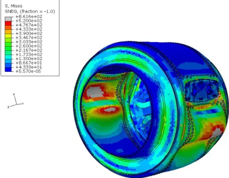
The stress distribution of the cylinder shows several areas where the yielding stress is achieved, in grey in figure 3.2. Not only in the area where the pressure is applied but the area affected by the boundary conditions imposed by the screw. It can be seen in this figure that the pressure because of the paddles is not relevant but the stiffness in this area is much bigger than in the rest of the cylinder. The following figures 3.2 and 3.4 show better the stress distribution using a different scale for the von Mises stress. The maximum value for the scale in figure 3.2 is set to 520 MPa, and the stress generated by the screws and the stress generated in the tripod can be shown more accurately.
44
Figure 3.2. von Mises average stress in the cylinder with applied loads
Figure 3.3. Cylinder displacement in mm
In figure 3.3, the absolute displacement is plotted and, as can be seen, the maximum displacement of the front cover is bigger than 20 mm. The deformation of the diameter of this part is representative and it would probably invalidate the design if the machine works under these loading conditions.
45
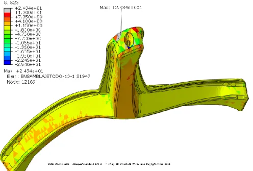
The stress distribution in the tripod is shown in figure 3.4. The maximum stress corresponds with the connection with the shaft (more than 900Mpa) this stress is possible only when working with a numerical model. The yield stress is reached in most of the regions of the tripod. For this figure, the Yielding Strength of the aluminium is used as maximum value for the scale (160 MPa).
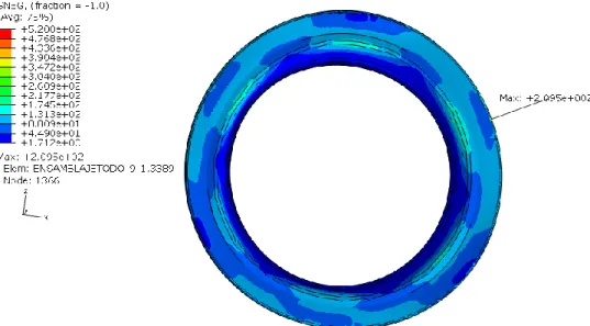
3.2. Simulation 2. Cylinder loaded with two opposite loads
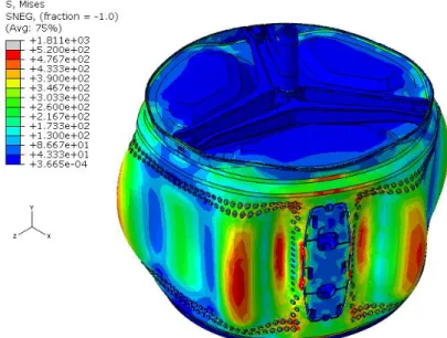
Simulation 2 (figure 3.5) represents the case where clothes are placed in small areas opposite to each other. The load is 50% of the maximum load allowed and there exists an unbalance between the loads. This unbalanced load forces the cylinder to spin at a speed smaller than the maximum, in this case 177 rad/s. It is considered to be an interesting case because the cylinder is loaded in a way that creates big deformations.
Figure 3.5. Explicative figure for simulation 2
In figure 3.6 it can be observed how the cylinder expands in the direction of the opposite loads, creating a deformation in the cylinder. It can also be observed that only in those regions affected by the presence of loads do tensions get to a point over 520 MPa, while in the rest of the cylinder these tensions keep a much smaller range.