Akademin för Innovation, Design och Teknik
Improving the product
development process with
additive manufacturing
Master thesis
Advanced level, 30 credits
Product and process development
Axel Staffanson
Philip Ragnartz
Tutor, company: Isabelle Rickardsson, Robby Kloos
Tutor, Mälardalens högskola: Bengt Erik Gustavsson
Examiner: Sten Grahn
I
A
BSTRACT
The following report consists of a master thesis (30 credits) within product development. The thesis is written by Philip Ragnartz and Axel Staffanson, both studying mechanical engineering at Mälardalens University.
Developing new components for a production line is costly and time consuming as they must be made from manual measurements and must go through all the conventional manufacturing (CM) steps. Eventual design mistakes will be discovered after the component have been manufactured and tested. To fix the design a completely new component must be designed and therefore double the overall lead time. The purpose of this thesis is to establish how additive manufacturing (AM) can best be used to minimize the cost and lead time in the development of new components.
The study was performed by looking at the current product development process in the automotive industry at a large company, here by referred to as company A. 56 components already manufactured at company A´s own tools department was examined and compared to different AM methods. The aim of this was to get a larger pool of data to get an average on production time and cost and see how this differ to the different AM methods. Additionally, two work holders were more closely examined in a case study. Work holder one is a component in the production line that occasionally must be remanufactured. It was examined if this problem could be solved with a desktop plastic printer to hold up for a production batch. Work holder two was the development of a new component, this was to examine the use of printing the component in an early stage impact the development process.
The findings from this study is that AM can today not be used in a cost efficient way in manufacturing or development of simple components. This is due to the cost of a metal 3D-printer is still very high, and the building material even higher. This results in components that gets very expensive to make compared to producing them with CM. For design evaluation to be cost efficient there will have to be a design fault in over 12 % of the newly design components for it to be cost effective to print the design for validation before sending it to be manufactured.
There are however a lot bigger potential savings in the lead time. Producing the end product with a metal 3D-printer can cut down the lead time up to 85 %. This is thanks to the fact that the printer will produce the component all in one step and therefore not get stuck in between different manufacturing processes. The same goes for design evaluation with printing the component in plastic to confirm the design and not risk having to wait for the component to be manufactured twice. Despite the facts that it is not cost efficient to use AM there are other factors that play an important role. To know that the designed components will work will create a certainty and allow the development process to continue. In some cases it will also allow the designer to improve the design to function better even if the first design would have worked. As AM is expanding machines and build materials will become cheaper. Eventually it will become cheaper to 3D-print even simple components compared to CM. When this occurs, a company cannot simply buy a 3D-printer and make it profitable. There is a learning curve with AM that will take time for the designers to adapt to. Therefore, it is good to start implementing it as soon as possible as it allows for more intricate designs and require experience to do so.
II
A
CKNOWLEDGEMENTS
Firstly, we would like to thank Company A for confiding us with the project and giving us access to their systems and employees. Especially warm appreciations to Isabelle Rickardsson (gear engineer) and Robby Kloos (production engineer) who guided the project and aided us to come in contact with relevant employees. Furthermore, we would also like to express gratitude to Svein Felde, head of the local tools department, for taking the time to answer our questions.
Secondly, we would like to thank Bengt Erik Gustafsson, lecturer in the school of Innovation, design and engineering. He provided us with his expertise about AM and numerous of books and reports about the subject.
Axel Staffanson Philip Ragnartz Maj 2018, Eskilstuna
III
D
ICTIONARY AND ABBREVIATIONS
DFAM Design for Additive manufacturing,
AM Additive manufacturing
AM system manufacturer AM system manufacturer refers to the developer of a certain machine or technology.
3D-printing technology Technology is the used collective term for the seven AM technologies recognized as the standard.
Conventional manufacturing In this thesis conventional manufacturing refers to milling, turning, casting and injection molding
CAD CAD stands for computer aided design and is a way to make 3D-models in a computer program
CAM Computer aided manufacturing which is a way to manufacture
CAD-parts in CNC machines
CNC Computer numerical control, how a computer can guide a machine
often with help of stepper motors
CM Conventional manufacturing
Desktop systems AM system manufacturer priced under 40 000 SEK
FDM Fused deposition modeling is another term used as for the standard technology Material extrusion
Industrial systems AM machines priced at 40 000 SEK or more
In-house All manufacturing performed at the studied production side are referred to as in-house.
IV
C
ONTENT
1
I
NTRODUCTION1
1.1 Background ... 1
1.2 Problem statement ... 1
1.3 Purpose, aim, and research question ... 2
1.4 Delimitations ... 2
2
M
ETHOD3
2.1 Well established methods. ... 32.2 Thesis methodology ... 4
2.2.1 Phase one, Startup ... 4
2.2.2 Phase two, data collection ... 4
2.2.3 Phase three, Analysis ... 6
2.2.4 Phase four, Implementation Plan ... 6
2.3 Validity and Reliability ... 6
3
T
HEORETIC FRAMEWORK7
3.1 3D-printing technologies ... 7 3.1.1 Material extrusion ... 7 3.1.2 Material Jetting ... 8 3.1.3 Binder Jetting ... 9 3.1.4 Sheet Lamination ... 93.1.5 Powder Bed Fusion ... 10
3.1.6 Vat Photopolymerization... 11
3.1.7 Directed Energy Deposition ... 12
3.2 Economy of additive manufacturing ... 12
3.3 The difference between cnc-machining and AM ... 13
3.4 Safety and health concerns with AM ... 14
3.5 Design for additive manufacturing (DFAM)... 15
4
E
MPIRICAL FINDINGS16
4.1 Qualitative data collection ... 164.1.1 Case study ... 16
4.1.2 Company visits ... 23
4.2 Quantitative data collection ... 25
5
I
MPLEMENTATION PLAN30
5.1 Optimal technology selection ... 30V
5.2 Guide lines when selecting a 3D-printer ... 31
5.3 Guide lines when using the printer ... 31
6
R
ESULT33
7
A
NALYSIS34
7.1 Research questions answered ... 347.2 DFAM ... 35
7.3 Calculation credibility ... 35
7.4 Quantitative compared with theoretical 3D-printing cost ... 35
8
C
ONCLUSION AND FUTURE RECOMMENDATIONS36
A
PPENDIX-1-
F
IGURES
Figure 1: Industrial AM systems area of use ... 1Figure 2: illustration of DRM´s iterative process ... 3
Figure 3: Break down of thesis data collection ... 4
Figure 4: Schematic of Material extrusion ... 8
Figure 5: Schematic of Material jetting ... 8
Figure 6: Schematic of Binder jetting ... 9
Figure 7: Schematic of Sheet lamination ... 10
Figure 8: Schematic of powder bed fusion ... 11
Figure 9: Schematic of Vat photopolymerization ... 11
Figure 10: Schematic of Directed energy deposition ... 12
Figure 11: Display of substituting a solid component with a lattice structure ... 15
Figure 12: Rendered representation of WH1 ... 17
Figure 13: Rendered representation of WH2 ... 17
Figure 14: Tolerances deviation for work holder one ... 18
Figure 15: Comparison of axis deviation ... 18
Figure 16: Diagram of the difference of inner and outer diameter ... 19
Figure 17: Representation of a conversion to a STL file ... 19
Figure 18: Tensile strength test ... 20
Figure 19: Result of tensile strength test with axial force (scenario one) ... 21
Figure 20: Result of tensile strength test with radial forces (scenario two) ... 22
Figure 21: Cost distribution on different technologies ... 26
Figure 22: Graph of design validation payoff ... 27
Figure 23: Cost comparison of different methods ... 28
Figure 24: Production time comparison of different methods ... 28
Figure 25: Similarities between lead time and number of processes ... 29
Figure 26: Illustration of lead time division to the right and material use to the left... 29
Figure 27: Optimal technology selection model ... 30
VI
T
ABLES
Table 1: Company background used for data collection ... 5
Table 2: Compilation over the conducted interviews ... 5
Table 3: The seven standard AM technologies defined by ASTM International ... 7
Table 4: Company background used for data collection ... 16
Table 5: Result of 3D-printed holes in relation with nozzle size and orientation ... 20
Table 6: Total printing cost for both work holders in different printing technologies. ... 23
Table 7: Quotation costs from company B and C ... 23
Table 8: Quotation cost for Binder jetting ... 23
Table 9: 3D-printer costs ... 25
Table 10: How AM technologies intersects with availably material ... 30
D
ISPOSITION
1 INTRODUCTION In the chapter the thesis background and problem statement are explained. Additive manufacturing (AM) is described, and its usefulness. The chapter continues with the thesis purpose, aim, and research questions followed by the delimitations.
2 METHOD Possible methods for this thesis are presented followed by the chosen method, and why it was chosen.
3 THEORETIC FRAMEWORK The chapter contains the theory of 3D-printing, how it can be used as well as a description of the different technologies. 4 EMPIRICAL FINDINGS The chapter presents the thesis primary data collection. It
begins with a short company background from which the data were collected. The chapter ends with a summarize of visits and corresponds from company A, B, and C.
5 IMPLEMENTION PLAN The chapter consist of a model aiding the technology selection, guidelines when selecting a 3D-printer, and a breakdown of areas that must be considered to be able to use the printer effectively.
6 RESULT The result of the thesis is presented
7 ANALYSES The analysis begins with answering the research questions that was presented in the introduction. Afterwards, the results credibility and the price difference between the calculated theoretical cost and the received quantitative are analyzed.
8 CONCLUSIONS AND FUTURE RECOMMENDATIONS
1
1 I
NTRODUCTION
In the following chapter the thesis background and problem statement will be explained. The paragraphs describe what additive manufacturing (AM) is, and why it is needed. The chapter continues with the thesis purpose, aim, and research questions followed by the delimitations.
1.1 B
ACKGROUND
Competition in the manufacturing industry is very tough. It is widely accepted that a company must investigate in continuous product development to gain competitive advantages. However, it is not uncommon that companies neglect the development of manufacturing technology (Ahlskog, 2015). A symbiosis exists between technologies and product development and only when both are simultaneously improved can competitive products with optimal lead time be achieved. (Ahlskog, 2015) Leif Johansson, former CEO of AB Volvo states: "The renewal of production technologies and innovative cost control are key areas to strengthen the competitiveness of Swedish industry. Perhaps even the most important areas to further develop the country's all immature products” (Ahlbom, 2013)
Implementing AM as a new manufacturing technology is today very popular. AM is the formalized term for what initially used to be called rapid prototyping or 3D Printing. The technology was initially used to create component representation before final release (Ian, et al., 2015). Since then the technology have evolved and today a variety of different materials exist, accuracy have improved, and the overall quality of the printed components. In Wohlers report, 61 manufacturers of industrial AM systems (those that sell for over 40 000 SEK) were asked to answer the question “How do your costumers use the parts built on your AM systems?” The survey shows companies use AM to produce functional parts most frequently. (WOHLERS ASSOCIATES, 2017)
Figure 1: Industrial AM systems area of use Source: Wohlers Associates, Inc
The basic principle of AM is that a component can be manufactured directly from Computer-Aided Design (CAD) programs. The component is constructed by adding material in layers, where each layer is a thin cross-section generated from the CAD model. The machine will then produce the component layer by layer building the next layer on top of the last one (Ian, et al., 2015).
1.2 P
ROBLEM STATEMENT
Late design changes in a product development process have a devastating effect on profitability. Incorrect design can happen for numerous reasons, failure to understand the need of the consumer is one common example. Numerous waste processes are incurred when components must be reworked and again transported. (Ullman, 2010). In a production line there are constant
2
improvements and development as new problems are discovered. If a problem occurs, it can cause a line to completely stop in wait for repairs or replacements. This is of course very costly, and the failed component must be replaced as quickly as possible. If the component were installed in the line long time ago it may have inadequate drawings. If so, it will lead to an uncertainty around dimensions when new components are designed. Therefore, the component is designed after what can be manually measured and must first be manufactured and then tested before the designed can be validated. Due to the risk of remanufacturing, the new components can often become more expensive and time consuming then intended.
1.3 P
URPOSE
,
AIM
,
AND RESEARCH QUESTION
The purpose of the thesis is to see how the implementation of AM in the development process can reduce lead time and cost of developing and manufacturing new components.
The aim of the thesis is to construct an implementation plan for how AM should be used to best improve the development process. The plan should help selected the most suitable AM technique by assessing the need of the company and provide guidelines for the usage.
The goal of the implementation is to reduce the manufacturing lead time of fixtures, tools and other necessary equipment needed for a production line by 50% and reduce the cost by 20%.
The following research questions were compiled:
RQ1: What effects does implementing AM have on the development process for a large manufacturing company?
RQ2: How can components for an automated manufacturing line be produced with AM in a cost-efficient way?
1.4 D
ELIMITATIONS
To provide a clear description of the thesis content the following list are areas that will not be studied.
All conclusions are based from data and research, but the result of the thesis will not be validated in the field. The implementation plan should be seen as theoretical proposal for how AM should best be used in a product development process.
The exact process how a company can select an AM system manufacturer will not be studied. Instead the focus lies on selection optimal AM technology and usage of the AM system. The implementation plan does however, provide guidelines when selecting an AM system manufacturer.
Evaluation if end products can be manufactured with AM instead of CM will not be studied. The benefits of design for additive manufacturing (DFAM) are only studied theoretically. The
actual cost difference when 3D-printning components designed for CM or AM are therefore not be studied.
Products manufactured using AM often requires post processing to fulfill the tolerance requirements. The cost for such processes and how it effects the cost efficiency of AM will not be studied.
Quotations from external AM manufacturers will be used as a comparison to buying and using an AM system. Using external companies as a producer for AM components will not be analyzed further.
3
2 M
ETHOD
Choosing the best methodological approached is a challenging task. Which one that is suitable depends on the researcher’s view of knowledge and on the nature of the research questions (Blessing & Amaresh , 2009). Possible methods for this thesis are presented below followed by the chosen method and why it was chosen.
2.1 W
ELL ESTABLISHED METHODS
.
Two possible work methods are presented below, first Wenell project workflow and then a model from the book Design Research Methodology.
Wenell project workflow
Wenell Management AB consult companies in Scandinavia to better succeed with their projects. To organize projects with high level of uncertainty Wendell project workflow consists of four phases. The first phase is the Prestudy. The phase begins with a description of the project, its background and its goals. It is important to establish the need for the project and if it is feasibility. The phase closes with a preliminary time plan and resource estimate. The Start phase follows with finalizing the project frames. The phase continues by analyzing which partners will influence the project and define project risks and opportunities. The phase ends with a premeditated timeframe and budget. The next phase, the Realization phase, uses daily management meetings to resolve issues and remove obstacles as early as possible. Wenell claims that the project should strive for early and successive deliveries rather than waiting for one big delivery at the end. In the last phase, the Closure phase the performance is evaluated against the projects aims and goals. The results are delivered and the responsibility for the project is passed to the receiver. (Wenell Management AB, u.d.)
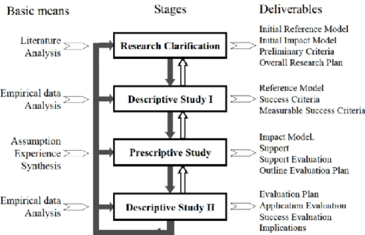
Design Research Methodology, DRM
The aim of DRM is to help design research become more efficient by providing guidelines for systematic planning of research. The method should be viewed as flexible processes, not as a linearly orientated processes which DRM claim produce designs of lesser quality. DRM consists of four stages: Research Clarification, Descriptive Study I, Prescriptive Study, and Descriptive Study II. Figure 2 below illustrate the iterative process and what each stage is expected to deliver (Blessing & Amaresh , 2009). Chosen deliverables from each stage will now be explained in more detail.
4 Deliverables from Research Clarification:
• Form an initial picture of the existing situation and of the desired outcome. • Formulate realistic research goals, problems, and questions. • Identify the project’s success criteria and how these can be measured. • Form a preliminary plan how to evaluate the outcome of the research against the success criteria. (Blessing & Amaresh , 2009)
Deliverables from Descriptive Study I:
• Elaborate the initial description with clear goals and why the research topic is relevant. • Identify factors that influence the success criteria and determine the effect. (Blessing & Amaresh , 2009) Deliverables from Prescriptive Study:
• Develop Intended Support that addresses the Key Factors. • Develop an Introduction Plan how to introduce, install, maintain and use and the support. • Describe the desired, improved situation that will occur when the Intended Support are in place. (Blessing & Amaresh , 2009)
Deliverables from Descriptive Study II:
• Identify whether the support works as intended and have the desired effect. • Evaluate the impact of the support. • Find improvement for the deliverables. (Blessing & Amaresh , 2009)
2.2 T
HESIS METHODOLOGY
Similar to Wenell project workflow the thesis was divided in phases, however those phases have been modified to better fit the thesis research questions. Four phases were constructed: startup, Data collection, Analysis, and Implementation plan. The Prestudy and Start phase from Wenell were similar to the phase Research clarification from DRM. They could be combined and adapted as the thesis startup phase. The mindset of success criteria from DRM was also adapted to the thesis. Unlike DRM the phases were performed in chronological order and fully completed before the next phase began.
2.2.1 P
HASE ONE
,
S
TARTUP
During this phase the thesis scope, surrounding conditions, and delimitations were defined. Partners that influence the project and affect later phases were established. The final step in the phase were to form a preliminary time plan.
2.2.2 P
HASE TWO
,
DATA COLLECTION
Figure 3 below shows how the thesis data collection was divided in to three sections. The thesis secondary data were collected first and then the primary data. The data were collected from three different companies, se company background in table 1 below.
5
Table 1: Company background used for data collection
Company A A large Swedish manufacturing company in the automotive industry with approximately 1300 employees (at the studied production site).
Company B A Swedish company that solely work with producing 3D-printed components for customers. They mainly work with plastic but can deliver both plastic and metal components for the costumers.
Company C One of the largest Nordic companies who supply laser welding. They have 18 employees where of two run their 3D-print department. They work with both SLS and EBM-technology.
Literature study
The secondary data consists of a literature study. Reading conclusions from earlier research provided a foundation and direction for the thesis. The keywords and databases used in the thesis can be found below. The phase continued with an academic study in which key elements affecting AM were researched further. The elements were selected from the reviewed articles, interviews and from previous knowledge. The elements are presented in chapter 3, Theoretic framework. Data regarding 3D-printers were collected directly from 3D system manufacturers.
Keywords: additive manufacturing, economic viability, cost accounting, cost benefit analysis, material efficiency, energy consumption, rapid prototyping, product development, design for additive manufacturing. Databases: Scopus, ScienceDirect, Google Scholar, Web of Science.
Case study
The case study was performed at company A. The purpose of the case study was to compare CM with AM by manufacturing the same component and evaluate the outcome. The chosen components were two work holders company A frequently experience problem with and the chosen AM technology was plastic material extrusion, see 3.1.1 Material extrusion. The case study consists of an economic comparison, strength comparison, tolerances comparison, printing orientation evaluation.
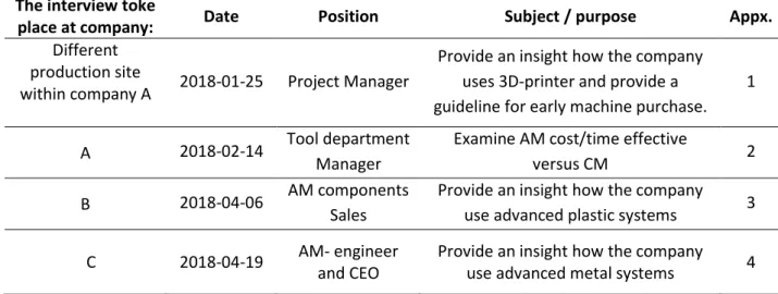
Interviews
The conducted interviews are compilation in the table 2 below. All interviews were performed as semi structured and the prepared questions can be found in appendix 1-4.
Table 2: Compilation over the conducted interviews
The interview toke
place at company: Date Position Subject / purpose Appx.
Different production site
within company A 2018-01-25 Project Manager
Provide an insight how the company uses 3D-printer and provide a guideline for early machine purchase.
1
A 2018-02-14 Tool department Manager
Examine AM cost/time effective
versus CM 2
B 2018-04-06 AM components
Sales
Provide an insight how the company use advanced plastic systems 3
C 2018-04-19 AM- engineer
and CEO
Provide an insight how the company use advanced metal systems 4
6
ERP-system
The data were collected using company A´s enterprise resource planning (ERP) system. Using the system, 56 components that had been previously manufactured using CM could be selected. The components were selected from what was most recently produced, with requirements of adequate drawings, article number, and that all manufacturing processes were done in-house. Using the ERP-system, data could be collected from the following parameters: order number, article number,
description, material, number of components manufactured, number of processes, order placed/started/delivered, exterior dimensions, outer dimensions, blank volume, production time, and
machining cost. To gather data from the parameter component volume all 56 components
2D-drawings where converted to 3D-models using CAD software.
2.2.3 P
HASE THREE
,
A
NALYSIS
In the fourth phase the collected data were analyzed. All form of analysis started with a familiarization of the data and then a categorization. Following, decisive data were plotted in numerous diagrams and compared in order to find patterns. The measurement data from the case study were plotted in a scatter diagram with the purpose to analyze the deviation and to find the root cause. A credibility assessment of the calculated economical parameters was performed by comparing it with prices from 3D systems manufacturers.
2.2.4 P
HASE FOUR
,
I
MPLEMENTATION
P
LAN
During the fifth phase a work process are presented how a company can proceed to select an AM technology. The process is adaptable to different needs, so the optimal AM technology can be chosen. To help guide the change an implementation plan has been establish how AM should best be used for the best outcome. The plan includes practicalities such as work routines, maintenance, ownership, and necessary related support equipment.
2.3 V
ALIDITY AND
R
ELIABILITY
The research usefulness is judged by its validity (measuring accuracy and what the study sets out to measure) and its reliability (whether the same results and findings are obtained in repetitive research under the same circumstances) (Blessing & Amaresh , 2009). In this thesis multiple data collection techniques have been used and due to the literature review, the data’s credibility can be evaluated. The study also includes a comparison of theoretic reasoning with empirical data, all required factors for high validity. The thesis provides a detailed data collection description that makes it possibility for other researchers to repeat the study again, a factor that ensures reliability.
7
3 T
HEORETIC FRAMEWORK
The following chapter contains the theory of 3D-printing in how it can be used as well as a description of the different 3D-printing technologies.
3.1 3D-
PRINTING TECHNOLOGIES
The range of different technologies and terminology can be confusing. To increase the confusion many system manufacturer like to differentiate themselves from their competitors by creating their own unique terminology. In reality, many of them works in similar ways. (WOHLERS ASSOCIATES, 2017) The first step to 3D-printing is always to create a digital 3D-model. These are usually made in a CAD program, but it is also possible to 3D-scan a physical object. When the 3D-model have been created, it will then be prepared using the 3D-printer own software. This include positioning the component, adding support material, and adjusting printing parameters. Thereafter the software slices the component into layers. The machine will then produce the component layer by layer, building the next layer on top of the last one. (WOHLERS ASSOCIATES, 2017) (Ian, et al., 2015)
In January 2012, ASTM International Committee F42 on AM Technologies recognized seven AM technologies as the new standard, see the list in table 3 below. (ASTM international , 2012)
Table 3: The seven standard AM technologies defined by ASTM International
3.1.1 M
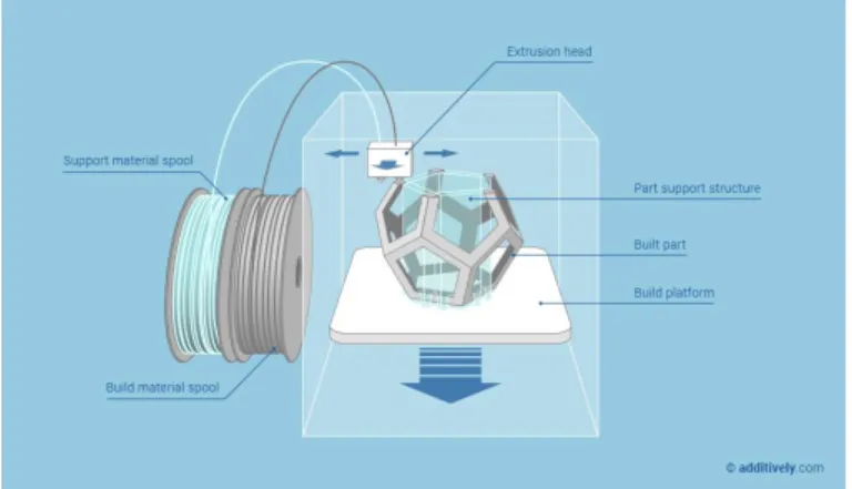
ATERIAL EXTRUSION
Machines falling in this category are often referred to as fused deposition modeling (FDM) printers. FDM printer is the most common printer technology as it is cheap and can be used with little to no extra equipment (Ian, et al., 2015). The material is melted and extruded through a nozzle onto a build plate. The build plate is lowered after each layer and the nozzle can then print on top of the layer beneath. With several nozzles it is possible to print with several materials at once. (Ian, et al., 2015) Figure 4 below illustrates the technology of Material extrusion.
8
Figure 4: Schematic of Material extrusion Source: additively.com
Material
The materials that are used are mainly thermoplastics such as Polylactide (PLA) and acrylonitrile butadiene styrene (ABS). Composite materials are also not uncommon where different plastics are mixed with other materials such as carbon fiber, para-aramid fibers, wood and more. (Ian, et al., 2015) There are also some machines that can print with a material that is composed of a metal powder and adhesive that holds it together. This can afterwards be processed to end up as a solid metal part (WOHLERS ASSOCIATES, 2017). There also exists machines that pump out concrete to build houses that falls under this category.
Applications
Material extrusion is the most commonly used technology. It does not require any support equipment and is therefore very well suited for office environments where it can be used for design validation, visual aids, prototypes, and education/ presentation models. (Ian, et al., 2015)
3.1.2 M
ATERIAL
J
ETTING
Material jetting is a liquid based system that hardens the material layer by layer. This technology first prints a layer of liquid on the build plate and then hardens it with a UV-light. The build plate is lowered and the next layer can be printed on top. As it lays out a liquid it requires some support beneath. As this technology creates solid component it needs another material to act as the support. This support material is often water soluble so that it can easily be removed. With one or more printer head several materials can be printed at once. (Ian, et al., 2015) The liquid is deposited through a printer head, similar to how a regular paper printer works. This means that the liquids can be mixed in the printer head to create components that change characteristics. Figure 5 below illustrates the technology of Material jetting.
Figure 5: Schematic of Material jetting source: additively.com
9
Material
The used liquid are often photopolymer or wax-like materials that can be used as investment-casting patterns. (Ian, et al., 2015)
Applications
These types of machines are often sensitive and needs some care and service to work properly. They can be used in an office, but the operator requires education. It takes some time to prepare the machines and to clean it afterwards to make sure it stays in good condition. The components produced have good tolerances and surface finish which can be used for design validation, prototypes and end products (Ian, et al., 2015).
3.1.3 B
INDER
J
ETTING
The part is fabricated by printing a binder into a powder bed. Only the binder fluid must be dispensed through the print heads which minimize the risk for clogging (Ian, et al., 2015). A layer consists of a spherical agglomerate of binder liquid and powder particles. Once a layer is completed, the build platform is lowered and a new layer of powder is spread onto it. The process repeats until the part is finished. The powder bed acts as support with the downside that all cavities will be filled. The unbound powder is removed in post process. Once the component has been removed, unprinted powders can be reused in subsequent builds. (Ian, et al., 2015) Metal component are possible to produce by binder jetting. However, they require sintering and infiltration of a second metal, commonly bronze, using a furnace. (WOHLERS ASSOCIATES, 2017) Components produced using binder jetting tend to have lacking surface finish and requires post processing to ensure good mechanical properties (Ian, et al., 2015). Figure 6 below illustrates the technology of Binder jetting.
Figure 6: Schematic of Binder jetting Source: additively.com
Material
The material available for commercial use are polymer composite with infiltration, stainless steel, bronze, ceramics, glass, Inconel, silica sand, ceramics, and inorganic sand. (Ian, et al., 2015)
Applications
Fabrication of sand molds and cores for sand casting, prototype, end production parts, and colored parts (Ian, et al., 2015). With binder jetting it is possible to print fully colored part, a great attribute for prototyping.
3.1.4 S
HEET
L
AMINATION
The technology involves layer-by-layer lamination of a thin material. The layers are usually cut using laser or mechanical cutting knife. The remaining material from the layer are diced in a crosshatch pattern and left as support. (Ian, et al., 2015) Depending on machine type, bonding between layers is achieved using adhesive bonding, thermal bonding, clamping, or ultrasonic welding. (Ian, et al., 2015)
10
Figure 7 illustrates a bonding technology where a heated roller is used to melt the adhesive layer and form a bond between layers.
Figure 7: Schematic of Sheet lamination
source: Materials Processing Technology by D.I. Wimpenny, B. Bryden, I.R. Pashby
Material
The most popular sheet lamination techniques use paper, thicknesses range from 0.07 to 0.2 mm (Ian, et al., 2015). However, potentially any sheet material that can be cut and bonded can be utilized. This include plastics, aluminum and low-carbon steel, and ceramics. When using ultrasonic welding materials like aluminum, titanium, stainless steel, brass, Inconel, and copper are commonly used (Ian, et al., 2015).
3.1.5 P
OWDER
B
ED
F
USION
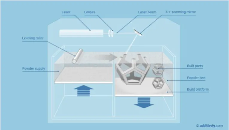
Machines falling in this category are often referred to as selective laser sintering (SLS) or Electron beam melting (EBM). The technology uses a fine powder that is spread across a build plate. The powder is commonly melted together with the previous layer by a laser. (Ian, et al., 2015) After a layer is finished the build plate is lowered, and a new layer of powder is spread out. Every layer completely fills the build room and all open spaces of the component, even where it may not be wanted. This needs to be considered in the design process so that there is a way to remove the powder. Powder bed fusion can be divided into two different groups that use either polymers or metals. In polymer-based systems, the powder act as the support material (Ian, et al., 2015). Metal based systems however, act a little different. Those systems need some support structures that are built in to the component due to stresses that occur in the material. The component also need to be attached to the build plate which means that it will have to be removed afterwards using a saw or wire electrical discharge machining. (Ian, et al., 2015) When printing with metal the build room will have to be either filled with a protective gas or vacuum to prevent the metal from oxidizing during the printing process. (Ian, et al., 2015) When the component is finished, and the build platform is filled with the unused powder and the operator must manually remove the excess powder. The unused powder can then be reused in the next print. Figure 8 below illustrates the technology of Powder bed fusion.
11
Figure 8: Schematic of powder bed fusion Source: additively.com
Material
All materials that can be melted and then solidified again can work with this technology. Thermoplastic materials are well suited as it melts the material and afterwards solidifies again. Metal based system typically uses stainless steels, titanium and its alloys, nickel-base alloys, some aluminum alloys, and cobalt-chrome. (Ian, et al., 2015)
Applications
This technology has many options in material and is a good option for when stronger metal component is needed. The strength lies in its ability to manufacture complex components. Polymer based systems are commonly used for prototyping and end products. It is especially useful for low-to-medium volume (Ian, et al., 2015).
3.1.6 V
AT
P
HOTOPOLYMERIZATION
Vat Photopolymerization uses a liquid that is poured in to a tank with a build plate on top of the surface. A UV-light or laser will then harden the first layer of the model on the build plate. The build plate is then lowered and the next layer can be built. After the model has been completed it can be removed from the build plate and rinsed from unhardened material and supports. The component can then be hardened in a curing oven. This creates an isotropic component with the same strength in all directions with very low built in stress. (Ian, et al., 2015) The technology produces components with fine tolerances and a good surface quality (Ian, et al., 2015). It does however have some drawbacks as the finished components become somewhat sensitive to UV-lights and become more brittle over time (Ian, et al., 2015). The machines themselves are quite sensitive and needs to be perfectly level for the liquid to spread correctly (Gustafsson, 2016). Figure 9 below illustrates the technology of vat photopolymerization.
Figure 9: Schematic of Vat photopolymerization Source: additively.com
12
Material
The materials used in this process is UV photopolymers which act as a type of plastic (Ian, et al., 2015). The material is toxic when it is unhardened and can be difficult to handle (Gustafsson, 2016). Due to the open tank and manual material handling this technology require a lot of safety procedures.
Applications
The technology can build components with good surface finish relatively fast (Ian, et al., 2015). This makes it perfect for design validation.
3.1.7 D
IRECTED
E
NERGY
D
EPOSITION
Directed energy deposition is often referred to as metal deposition technology due to its lone use of metal material (Ian, et al., 2015). The technology simultaneously heats the focused surface and melt material that is being deposited by directing energy into a narrow region. The technology typically uses a laser or electron beam to melt metal powders or wires. (Ian, et al., 2015) Deposition typically occurs in a vertical manner using 3-axis systems. However, 4- or 5-axis systems using either robotic arms or rotary tables are also available. In addition, hybrid machines combining the technology with CNC milling are available which are especially useful for overhaul and repair. (Ian, et al., 2015) Figure 10 below illustrates the technology of Directed energy deposition.
Figure 10: Schematic of Directed energy deposition Source: sciaky
Material
The used material is typically in powder form or wire form. Any powder material or powder mixture that can be melted can be used. (Ian, et al., 2015)
Applications
Directed energy deposition are capable of producing complex, fully dense metal components. It can also be utilized to repair defects or service damaged high-technology components. (Ian, et al., 2015)
3.2 E
CONOMY OF ADDITIVE MANUFACTURING
There are several different aspects when it comes to the economy of additive manufacturing. It depends strongly on what kind of things it is that are to be produced, what material and the size of the component. The complexity of the component also has a big impact on the verdict of the economy. A component that can be simply produced with conventional manufacturing (CM) will be hard justify manufacture with AM from an economical aspect. (Ian, et al., 2015)
13
The volume of products to be produced has a big effect on the overall cost, it is also affected on other aspects as mentioned above as well. But in general it is more costly to manufacture fewer volumes of a component with CM as it often requires new tools and fixtures regardless of how many products that is to be produced. (Ian, et al., 2015) (Nourredine Boubekri, 2015) In some cases, for producing electronic components the roof for when it stops being economical to make with AM can be up to 121 000 parts. (Nourredine Boubekri, 2015)
The material cost is another important factor. The material used in 3D-printing machines are a lot more expensive than the material that can be used in CM. Plastics for 3D-printers can vary from 50 to 200 euro per kilo, compared to plastics for injection molding that cost 2 to 4 euro per kilo (Nourredine Boubekri, 2015) (Ian, et al., 2015). The production time per produced component will also have a big factor in the evaluation between AM and CM. Producing components with CM will most of the time be a lot quicker when it is up and running compared to AM. (Ian, et al., 2015) Today 3D-systems are very expensive. This is mostly due to a small production scale and high development cost. The printers can involve some expensive parts such as lasers and galvanic mirrors. But other than that, it is mechanically a simple machine. As the demand of printers increase they can be mass-produced and the price would drop dramatically. The same goes for the material. There are not a lot of producers of material and so the competition is too low to drive the prices down. (WOHLERS ASSOCIATES, 2017). Another economical aspect of 3D-printing is outsourced manufacturing. The CAD file needed for the 3D-print can easily be shared between locations by a simple email. This opens the possibility for an external company to produce the component and then send it back to the designer. The exchange could potentially remove the need to invest expensive 3D-systems (Berman, 2012). The negative aspect of the increasing availability of CAD-files is the risk for cloned or pirated products. A major fear exists of sharing the product and tighten existing intellectual property rules are a debated subject (Berman, 2012).
3.3 T
HE DIFFERENCE BETWEEN CNC
-
MACHINING AND
AM
Some of the big differences between CM and AM can be summarized in the following areas. This section is mainly focused on manufacturing new components in low series and not series production in a production line.
Material
AM is originally developed to work with different types of polymers and waxes but have now developed into metal materials as well. There are a lot of different plastics available and even material reinforced with carbon fiber exists. However, compared to CM the available material are no way near as extensive. Regarding metal printers, there are even less materials available. The limitation that exclude some alloys are because they separate in the melting process. (Ian, et al., 2015)
Speed
The speed of a 3D-printer is usually slower at adding material compared to the rate a CNC mill can remove material (Ian, et al., 2015). With a CNC mill there are usually a lot more steps involved that requires planning and for the machine operator to be more present (Ian, et al., 2015). The component will often have to be repositioned and in some cases custom fixtures and supports must be created to be able to machine the component.
In a 3D-printer there is also possible to print several components in the same print as long as they can fit in the machines build space. Different machines can also build the components in different materials at the same time. This can speed up the process significantly as the printer can work unsupervised and overnight.
14
Complexity
With CM some geometrics can be very hard to manufacture. It may require custom fixtures and powerful five-axis CNC mills. This will lengthen the programing and setup of the milling procedure. But even with five-axis machines there are some geometries that simply cannot be made due to the way they operate. For example, there must be room for the spindle to access the area that are to be processed. In these scenarios the component would have to be separated to several components that after machining can be assembled. This requires extra work both beforehand and after manufacturing. With 3D-printing you can reduce the number of steps required to produce the component. The printing software will take care the planning of the manufacturing process. It does not matter how complex the component is, it is still as easy to manufacture. (Ian, et al., 2015)
Accuracy
Both 3D-printers and CM processes generally have very good resolution and accuracy. A CNC mill and most 3D-printers work with three axis and are operated by stepper motors which often gives the machine the ability to be positioned within a couple of microns. This does however not give the finished component the same tolerance. With a mill the stiffness of the machine as well as the accuracy in the end mill will affect the outcome (Ian, et al., 2015). With a 3D-printer the building technology will decide how close to the actual drawing the component will be. However, with a 3D-printer the quality of the surface finish depends on the layer height and in the end, it may require some additional machining. (Ian, et al., 2015) (Josef, et al., 2015)
Programming
To program a CNC mill can be very difficult and time consuming as it involves settings as tool choice, machining speeds, and machining strategies. With a 3D-printer there are also settings that can be adjusted, but in comparison there is not as many settings to adjust as the system developers have developed good settings (Thornton, 2015) (Ian, et al., 2015). It depends on the machine but in general you cannot make mistakes that will damage the machine as badly as you can with a mill. Preparing a 3D print using material extrusion technology does not require much education. A more complex mill often has up to five axis and can become very difficult to program (Ian, et al., 2015).
Cost
In a comparison between making a prototype for a plastic piece in a car it was estimated that with CM it would have cost around 4000 euro to produce the component and with the help of AM it could be made with only 400 euro (Josef, et al., 2016). This was made by printing the component with material extrusion technology and creating a silicone mold. The final component could then be cast in the silicone mold. When using AM create special tools to form the component is not necessary. As these tools can be very costly it becomes sustainable to spend a lot of money on a 3D-printed component when you are producing a low volume of prototypes. (Josef, et al., 2015)
3.4
S
AFETY AND HEALTH CONCERNS WITH
AM
As there is a lot of variety in the type of 3D-printers they can be categorized into two categories, desktop printers and industrial printers. Desktop 3D printers are systems that are priced below 40 000 SEK and industrial systems are priced above (WOHLERS ASSOCIATES, 2017).
With AM safety concerns varies between different machines and manufactures. There is no immediate danger when using a desktop printer (Brent, et al., 2013). Almost all available material for Material extrusion technology is approved according to the REACH regulation and does not have any harmful effects, there can however be some concerns when the material is melted. Some gases can be emitted which can cause nausea and headache. And there are also some nanoparticles that are smaller than 100 nanometer that become airborne when in use. There is however no verdict on how harmful these nanoparticles are and no acceptable emission levels. (Brent, et al., 2013)
15
3.5 D
ESIGN FOR ADDITIVE MANUFACTURING
(DFAM)
To use the full potential of AM the component must be designed with consideration to the printing technology and to the intended printing machine. It is important to fully understand how the design will affect the outcome. When using a technology that requires support material it is important to design the component correctly. Support material generally result in worse surface quality and extended part cleanup in post process, therefore it is a good idea to try and minimize the amount. (Ian, et al., 2015) The rule of thumb is to avoid designing overhangs with a greater angle than 45 degrees. The printing orientation also effect the amount of required support. Features on the component facing towards the printing orientation generally gets the best quality. When using material extrusion technology, upward-facing surfaces are smoothed by the extrusion tip and for powder beds the surface are smooth since they solidify against air. (Ian, et al., 2015) The positioning of the component must therefore be compared against the importance of different surfaces. Support material are often unavoidable, and thus the removal must be accounted for. Components with cavities must be design with an access hole so the supports material can be removed. Similarly, cavities printed with vat photopolymerization processes requires a drain holes for any trapped liquid. The strength with AM lies with its ability to print advanced geometry. Components that can easily be manufactured using CM may not be suited for 3D-printing (Johansson, 2018) (Ian, et al., 2015). To improve the components suitability hollow features can be included in the design. Commonly, components designed for AM are often constructed with a honeycomb- or lattice structure. Software exist that can substitute parts a solid component with a lattice structure, se figure 11 below for an example. The main benefits of doing this are the cost reduction due to the use of less material, providing support and strengthen the part, reducing the build time, and the reduced final mass and volume (Ian, et al., 2015).
Figure 11: Display of substituting a solid component with a lattice structure Source: 3dsystems.com and meshify.dk
The build volume of the intended machine must be taken in to consideration when designing larger components. In some cases, due to the limitations of the build plate the part must be broken down into segments. The separation must then facilitate reassembly, for example by using interlocking features or maximizing surface area so that adhesives can be most effective (Ian, et al., 2015). AM can also be used to do the opposite, combining multiple parts. For example, it is possible to print fully assembled hinge structures by providing clearance around the moving features or reducing complex assemblies to a single component (Ian, et al., 2015). When using DFAM the designer should always evaluate if multiple components can be combined.
16
4 E
MPIRICAL FINDINGS
The following chapter presents the thesis primary data. The chapter begins with a short company background from which the data were collected. The data from the qualitative study and case study were collected at company A. The chapter ends with a summarize of visits and corresponds from company A, B, and C.
Table 4: Company background used for data collection
Company A A large Swedish manufacturing company in the automotive industry with approximately 1300 employees (at the studied production site).
Company B A Swedish company that solely work with producing 3D-printed components for customers. They mainly work with plastic but can deliver both plastic and metal components for the costumers.
Company C One of the largest Nordic companies who supply laser welding. They have 18 employees where of two run their 3D-print department. They work with both SLS and EBM-technology.
4.1 Q
UALITATIVE DATA COLLECTION
The qualitative data collection consists of a case study, interviews and observations. The purposes of the studies were to follow the development process from the beginning and study the impact AM can have. The studies were conducted in its natural setting to best gather significant data.
4.1.1 C
ASE STUDY
At the request of company A, the impact of AM were to be reviewed for two different work holders. The case consists of an economic comparison, strength comparison, tolerances comparison, and printing orientation evaluation.
Background, Work Holder One
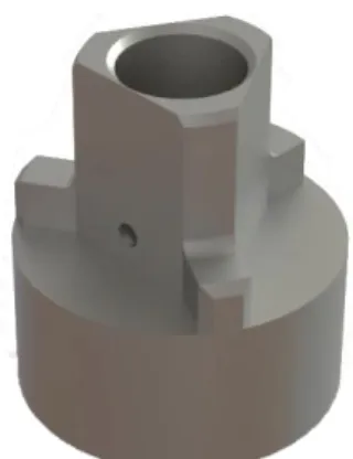
In the production line there is an occasional problem with the work holder on the carrier of the cast blanks to the first lathe. The root cause of the problem is that the work holder and the blanks tolerances does not match. When a batch is delivered close to the MIN tolerance it can cause the work holder to get stuck. When the lathe then picks up the blank, the work holder is pulled out of the carrier and into the machine. This can damage the lathe and cause a costly crash that stops the production line. When this situation occurs, the holder is today modified to compensate for the deviation. However, when the batch is delivered close to the MAX tolerances the modified work holder will no longer center the blanks, and so a completely new work holder must be manufactured. Producing work holders is both very costly and time consuming. This can also lead to additional cost if the production line must stop and wait for the modification or the completely reproduced work holder. The case study is made to test if the work holder can be 3D-printed with a desktop printer counteract the deviation. The described work holder can be seen in figure 12 below.
17
Figure 12: Rendered representation of WH1
Background, Work Holder Two
Due to a change in how a component is clamped in the lathe a new work holder must be designed. Currently, the component is centered using the inside diameter and clamped using the outside surface, company A vision is to do the opposite. The problem with the change is that no drawings exist of the machine parts. The new design will therefore be based entirely from manual measurements. The lack of information means an uncertainty in the new designs compatibility with the machine. To minimize the risk of incorrect design, the part will therefore first be manufactured using FDM technology. The described work holder can be seen in figure 13 below.
Figure 13: Rendered representation of WH2
Printing orientation and material
The strength and overall function of FDM components are mainly determined by the printing orientation and the material used. Printing cylindrical components on their top or bottom will result in minimal support material and higher surface quality. The orientation makes the part strong against bending loads but at the same time weaker against shearing. To study the difference, work holder one was printed both as standing and sideways. Due to the geometry of work holder two, it was not suitable to be print sideways. To study the effect of other determent factor, the material, both work holders were printed in PLA and nylon.
Tolerances
The printed components were sent to company A´s measuring lab to evaluate if the components fulfill the required tolerances and to evaluate how the printing orientation and material affect the tolerances. The full measurement datasheet can be seen in appendix 5. The lab could take accurate measurements using a coordinate measuring machine. In figure 14 below, the deviation on all the measurements can be seen. On the x-axis are the designed measurement and on the y-axis is the deviation. The different bars in colors represents the different printed components as seen. Despite that the component have been printed in two different orientations and two different materials the measurements are still deviating to the same side on the individual measurement. This means that the deviation is not directly related to either the printing orientation or the material.
18
Figure 14: Tolerances deviation for work holder one
To further try to find the cause of the deviations the measurements are grouped in different categories. In figure 15 they are grouped by the direction the measurement has been printed. The x and y direction have been grouped together as the component are built the same way in these directions. But as seen in the graph, the deviation in scattered all the way from almost -1 to +1 millimeters independent of the printing direction.
Figure 15: Comparison of axis deviation
The difference between the measurements between inner diameter and outer diameter can be seen in figure 16 below. It is here clearly shown how the dimensions of inner diameters holes shrink and outside diameter tend to grow.
19
Figure 16: Diagram of the difference of inner and outer diameter
The reason for the deviation is related to mainly three causes. Firstly, when the part is saved in to a STL file from the CAD software all surfaces are divided, usually in to triangles. This means that the holes are no longer circular but made up of a number of straight lines as seen in figure 17 below. Even though this is a very small deviation it can cause the hole to become smaller, especially if it is saved with a low tolerance setting as seen to the left in figure 17. Secondly, the printed material will shrink when it is cooled down. If the material is being printed in a straight line the deformation will not be an issue because it can only retract and not deviate from its path. Another reason why it is not an issue is because the layer cannot move as there are other layers next to it. However, when the layer is printed in an arc the material will want to shrink in to the ark. Regarding the outer diameter there will be support material that stop the movement but the inner diameter have nothing to stop the filament from shrinking. Lastly, the nozzle is pushing the material down to the previous layer, but as the nozzle is constantly moving it will also pull the material. This are not an issue when printing in straight lines or arks with a large radius since the pulling force is low. However, when printing small a diameter the nozzle will move at a higher angle and therefore the pulling effect is higher. This will cause the material to get placed closer towards the center of the arc. The result is that holes, especially small holes are printed smaller than they are intended.
Figure 17: Representation of a conversion to a STL file
When it was clear that dimensions of inner diameters shrink the question rose if changing the printing orientation or using a smaller nozzle would result in better tolerances. To test the hypothesis a plate with holes in varying sizes were printed. The measurements of the holes are presented in Table 5 below. The size in the table is the average from a minimum of five measurements performed
20
with a caliper. The plate was printed in nylon and with a layer height of 0,1 millimeter. All the measurements presented below are in millimeter.
Table 5: Result of 3D-printed holes in relation with nozzle size and orientation
Nozzle: 0,4 Orientation: Sideways Nozzle: 0,25 Orientation: Sideways Nozzle: 0,25 Orientation: Standing CAD Size Difference CAD Size Difference CAD Size Difference
50 49,89 0,11 30 29,98 0,02 30 29,75 0,25 30 29,91 0,09 20 19,96 0,04 20 19,75 0,25 20 19,87 0,13 15 14,94 0,06 15 14,84 0,16 15 14,89 0,11 12 11,92 0,08 12 11,9 0,1 10 9,74 0,26 10 9,91 0,09 10 9,92 0,08 8 7,79 0,21 8 7,86 0,14 8 7,95 0,05 6 5,77 0,23 5 4,8 0,2 5 5 0 5 4,79 0,21 3 2,74 0,26 3 2,97 0,03 4 3,76 0,24 3 2,73 0,27
The test clearly shows that using a smaller nozzle result in better tolerances. However, when printing sideways holes with size 8 millimeter or less the same inaccuracy still occurs. Standing orientation on the other hand succeed in print very exact small holes, but at the same time have greater inaccuracy when printing larger holes.
Tensile strength
The work holder will mainly be exposed for axial forces, but as the holder moves some radial forces occurs. The printed components were tested in a tensile strength machine in two different scenarios, illustrated in figure 18. Both scenarios were conducted in stages. Firstly, with lower load to simulate the real usage in the production line and secondly, with a higher force to study the breaking point.
Figure 18: Tensile strength test
21
Figure 19 below show the test result in a load-deformation curve from the first scenario. None of the work holders experienced any plastic deformation from the lower loads. The most durable component was the one printed with a standing orientation in nylon. It withstood the remarkable force of 9000N before permanent damage started to occur.
Figure 19: Result of tensile strength test with axial force (scenario one) 0 20 40 60 80 100 120 140 160 180 0 0,2 0,4 Load ( N ) Deformation (mm)
100N
PLA, Standing Nylon, Sideways PLA, Sideways Nylon, Standing 0 200 400 600 800 1000 1200 1400 0 0,5 Load ( N ) Deformation (mm)1000N
PLA, Sideways PLA, Standing Nylon, Sideways Nylon, Standing 0 1000 2000 3000 4000 5000 6000 7000 8000 9000 10000 0 1 2 3 4 5 Load ( N ) Deformation (mm)Breaking point
PLA, Sideways PLA, Standing Nylon, Sideways Nylon, Standing22
Figure 20 shows the test result from the second scenario in a load-deformation curve. None of the work holders experienced any deformation from the lower loads. The component printed in nylon were so tough that an additional experiment was conducted. In the experiment, the load was not removed until the component had deformed 25 mm. The one printed with a sideways orientation were so thought that it never completely broke in to two parts.
Figure 20: Result of tensile strength test with radial forces (scenario two) 0 200 400 600 800 1000 1200 0 10 20 Load ( N ) Deformation (mm)
1000N
PLA, Sideways PLA, Standing Nylon, Sideways Nylon, Standing -500 0 500 1000 1500 2000 2500 3000 0 2 4 6 8 10 Load ( N ) Deformation (mm)Breaking point
PLA, SIideways PLA, Standing Nylon, Sideways Nylon, Standing 0 500 1000 1500 2000 2500 -5 5 15 25 Load ( N ) Deformation (mm)Toughtness test
Nylon, Sideways Nylon, Standing23
Economic comparison
The printing cost for both work holders were calculated using the same formula presented in the quantitative data collection. A quotation requests were send to company A´s local tool department to get an estimate for the cost off CM. The theoretic cost was all cheaper than the cost for CM, as can be seen in table 6 below.
Table 6: Total printing cost for both work holders in different printing technologies.
Work holder one Work holder two
Metal FDM 1909 SEK 1345 SEK
Metal FDM 2 2222 SEK 1710 SEK
Metal EBM 4405 SEK 3092 SEK
Metal SLS 5043 SEK 3493 SEK
Plastic FDM 303 SEK 290 SEK
Conventional
manufacturing 6420 SEK 5870 SEK
To get a better understanding of the cost, quotation requests were also send out to companies. Another purpose of the request was to study the possibility of outsourcing manufacturing. Company B, C and a third one replied as seen below in table 7 and 8. This includes printing cost for metal SLS technology, removal of support material and material cost (maraging steel corresponding to European 1.2709). The price also includes a profit margin that accommodates for production error and faults. Company A claimed a two weeks lead time and company B claimed 20 work days.
Table 7: Quotation costs from company B and C
Work holder one Work holder two Together
Company C 22 550 SEK 20 250 SEK 31 900 SEK
Company B 27 254 SEK 19 899 SEK /
For the second one the price below includes printing cost, removal of support material, post processing, and material cost (stainless steel infiltrated with bronze: 90% Cu and 10% Sn). The company claimed a 3-4 weeks lead time.
Table 8: Quotation cost for Binder jetting
Work holder one Work holder two
Binder jetting 3763 SEK 2998 SEK
4.1.2 C
OMPANY VISITS
Two visits to different companies were made to get a better understanding on using 3D-printers on an industrial level. The two companies as described earlier is working with producing 3D-printed models for their customers. Company B works with plastic and company C in both plastic and metal. A visit was also made to another facility within company A, all visits was executed as semi constructed interviews.