DOCT OR AL DISSERT A TION IN ODONT OL OG Y R AMESH C HO WDHAR Y MALMÖ UNIVERSIT Y MALMÖ UNIVERSITY
RAMESH CHOWDHARY
ON EFFICACY OF IMPLANT
THREAD DESIGN FOR BONE
STIMULATION
isbn 978-91-7104-396-2 ON EFFIC A CY OF IMPL ANT THREAD DESIGN FOR BONE S TIMUL A TIONO N E F F I C A C Y O F I M P L A N T T H R E A D D E S I G N F O R B O N E S T I M U L A T I O N
Malmö University
Faculty of Odontology Doctoral Dissertations 2014
© Ramesh Chowdhary 2014 ISBN 978-91-7104-396-2 Holmbergs i Malmö AB 2014
RAMESH CHOWDHARY
ON EFFICACY OF IMPLANT
THREAD DESIGN FOR BONE
STIMULATION
Malmö University, 2014
Faculty of Odontology
Department of Prosthodontics
This publication is also available at: www.mah.se/muep
Dedicated to my father, mother, my beloved wife, Nagu, and my two boys, Rohan and Rishab
This thesis represents number 45 in a series of investigations on implants, hard tissue and the locomotor apparatus originating from the Department of Biomaterials, University of Gothenburg and the Department of Prosthodontics/Material sciences, Malmö University, Sweden.
1. Anders R Eriksson DDS, 1984. Heat-induced Bone Tissue
Injury. An in vivo investigation of heat tolerance of bone tissue and temperature rise in the drilling of cortical bone. Thesis defended 21.2.1984. External examiner: Docent K-G. Thorngren.
2. Magnus Jacobsson MD, 1985. On Bone Behaviour after
Irradiation. Thesis defended 29.4.1985. External examiner: Docent A. Nathanson.
3. Fredric Buch MD, 1985. On Electrical Stimulation of Bone
Tissue. Thesis defended 28.5.1985. External examiner: Docent T. Ejsing-Jörgensen.
4. Peter Kälebo MD, 1987. On Experimental Bone Regeneration in
Titanium Implants. A quantitative microradiographic and histologic investigation using the Bone Harvest Chamber. Thesis defended 1.10.1987. External examiner: Docent N. Egund.
5. Lars Carlsson MD, 1989. On the Development of a new Concept
for Orthopaedic Implant Fixation. Thesis defended 2.12.1989. External examiner: Docent L-Å Broström.
6. Tord Röstlund MD, 1990. On the Development of a New
Arthroplasty. Thesis defended 19.1.1990. External examiner: Docent Å. Carlsson.
7. Carina Johansson Res Tech, 1991. On Tissue Reaction to Metal
Implants. Thesis defended 12.4.1991. External examiner: Professor K. Nilner.
8. Lars Sennerby DDS, 1991. On the Bone Tissue Response to
Titanium Implants. Thesis defended 24.9.1991. External examiner: Dr J.E. Davies.
9. Per Morberg MD, 1991. On Bone Tissue Reactions to Acrylic
Cement. Thesis defended 19.12.1991. External examiner: Docent K. Obrant.
10. Ulla Myhr PT, 1994. On Factors of Importance for Sitting in
Children with Cerebral Palsy. Thesis defended 15.4.1994. External examiner: Docent K. Harms-Ringdahl.
11. Magnus Gottlander MD, 1994. On Hard Tissue Reactions
to Hydroxyapatite-Coated Titanium Implants. Thesis defended 25.11.1994. External examiner: Docent P. Aspenberg.
12. Edward Ebramzadeh MScEng, 1995. On Factors Affecting
Long-Term Outcome of Total Hip Replacements. Thesis defended 6.2.1995. External examiner: Docent L. Linder.
13. Patricia Campbell BA, 1995. On Aseptic Loosening in Total
Hip Replacement: the Role of UHMWPE Wear Particles. Thesis defended 7.2.1995. External examiner: Professor D. Howie.
14. Ann Wennerberg DDS, 1996. On Surface Roughness and Implant
Incorporation. Thesis defended 19.4.1996. External examiner: Professor P-O. Glantz.
15. Neil Meredith BDS MSc FDS RCSm 1997. On the Clinical
Measurement of Implant Stability Osseointegration. Thesis defended 3.6.1997. External examiner: Professor J. Brunski.
16. Lars Rasmusson DDS, 1998. On Implant Integration in
Membrane-Induced and Grafter Bone. Thesis defended 4.12.1998. External examiner: Professor R. Haanaes.
17. Thay Q Lee MSc, 1999. On the Biomechanics of the Patellfemoral
Joint and Patellar Resurfacing in Total Knee Arthroplasty. Thesis defended 19.4.1999. External examiner: Docent G. Nemeth.
18. Anna Karin Lundgren DDS, 1999. On Factors Influencing Guided
Regeneration and Augmentation of Intramembraneous Bone. Thesis defended 7.5.1999. External examiner: Professor B. Klinge.
19. Carl-Johan Ivanoff DDS, 1999. On Surgical and Impant Related
Factors Influencing Integration and Function of Titanium Implants. Experimental and Clinical Aspects. Thesis defended 12.5.1999. External examiner: Professor B. Rosenquist.
20. Bertil Friberg DDS MDS, 1999. On Bone Quality and Implant
Stability Measurements. Thesis defended 12.11.1999. External examiner: Docent P. Åstrand.
21. Åse Allansdotter Johansson MD, 1999. On Implant Integration in
Irradiated Bone. An Experimental Study of the Effects of Hyperbaric Oxygeneration and Delayed Implant Placement. Thesis defended 8.12.1999. External examiner: Docent K. Arvidsson-Fyrberg.
22. Börje Svensson FFS, 2000. On Costochondral Grafts Replacing
Mandibular Condyles in Juvenile Chronic Arthritis. A Clinical, Histologic and Experimental Study. Thesis defended 22.5.2000. External examiner: Professor Ch. Lindqvist.
23. Warren Macdonald BEng, MPhil, 2000. On Component
Integration on Total Hip Arthroplasties: Pre-Clinical Evaluations. Thesis defended 1.9.2000. External examiner: Dr A.J.C. Lee.
24. Magne Røkkum MD, 2001. On Late Complications with HA
Coated Hip Asthroplasties. Thesis defended 12.10.2001. External examiner: Professor P. Benum.
25. Carin Hallgren Höstner DDS, 2001. On the Bone Response to
Different Implant Textures. A 3D analysis of roughness, wavelength and surface pattern of experimental implants. Thesis defended 19.11.2001. External examiner: Professor S. Lundgren.
26. Young-Taeg Sul DDS, 2002. On the Bone Response to Oxidised
Titanium Implants: The role of microporous structure and chemical composition of the surface oxide in enhanced osseointegration. Thesis defended 7.6.2002. External examiner: Professor J.E. Ellingsen.
27. Victoria Franke Stenport DDS, 2002. On Growth Factors and
Titanium Implant Integration in Bone. Thesis defended 11.6.2002. External examiner: Associate Professor E. Solheim.
28. Mikael Sundfeldt MD, 2002. On the Aetiology of Aseptic
Loosening in Joint Arthroplasties and Routes to Improved cemented Fixation. Thesis defended 14.6.2002. External examiner: Professor N. Dahlén.
29. Christer Slotte CCS, 2003. On Surgical Techniques to Increase
Bone Density and Volume. Studies in the Rat and the Rabbit. Thesis defended 13.6.2003. External examiner: Professor C.H.F. Hämmerle.
30. Anna Arvidsson MSc, 2003. On Surface Mediated Interactions
Related to Chemomechanival Caries Removal. Effects on surrounding tissues and materials. Thesis defended 28.11.2003. External examiner: Professor P. Tengvall.
31. Pia Bolind DDS, 2004. On 606 retrieved oral and cranio-facial
implants. An analysis of consecutively received human specimens. Thesis defended 17.12.2004. External examiner: Professor A. Piattelli.
32. Patricia Miranda Burgos DDS, 2006. On the influence of micro-
and macroscopic surface modifications on bone integration of titanium implants. Thesis defended 1.9.2006. External examiner: Professor A. Piattelli.
33. Jonas P Becktor DDS, 2006. On factors influencing the outcome
of various techniques using, endosseous implants for reconstruction of the atrophic edentulous and partially dentate maxilla. Thesis defended 17.11.2006. External examiner: Professor K.F. Moos.
34. Anna Göransson DDS, 2006. On Possibly Bioactive CP Titanium
Surfaces. Thesis defended 8.12.2006. External examiner: Professor B. Melsen.
35. Andreas Thor DDS, 2006. On platelet-rich plasma in
reconstructive dental implant surgery. Thesis defended 8.12.2006. External examiner: Professor E.M. Pinholt.
36. Luiz Meirelles DDS MSc, 2007. On Nano Size Structures For
Enhanced Early Bone Formation. Thesis defended 13.6.2007. External examiner: Professor Lyndon F. Cooper.
37. Pär-Olov Östman DDS, 2007. On various protocols for direct
loading of implant-supported fixed prostheses. Thesis defended 21.12.2007. External examiner: Professor B. Klinge.
38. Kerstin Fischer DDS, 2008. On immediate/early loading of
implant supported prostheses in the maxilla. Thesis defended 8.2.2008. External examiner: Professor K. Arvidsson Fyrberg.
39. Alf Eliasson 2008. On the role of number of fixtures, surgical
technique and timing of loading. Thesis defended 23.5.2008. External examiner: Professor K. Arvidsson Fyrberg.
40. Victoria Fröjd DDS, 2010. On Ca2+ incorporation and
nanoporosity of titanium surfaces and the effect on implant performance. Thesis defended 26.11.2010. External examiner: Professor J.E. Ellingsen.
41. Lory Melin Svanborg DDS, 2011. On the importance of nanometer
structures for implant incorporation in bone tissue. Thesis defended 01.06.2011. External examiner: Associate professor C. Dahlin.
42. Byung-Soo Kang Msc, 2011. On the bone tissue response to
surface chemistry modifications of titanium implants. Thesis defended 30.09.2011. External examiner: Professor J. Pan.
43. Kostas Bougas DDS, 2012. On the influence of biochemical
coating on implant bone incorporation. Thesis defended 12.12.2012. External examiner: Professor T. Berglundh.
44. Arne Mordenfeld DDS, 2013. On tissue reactions to and
resorption of bone substitutes. Thesis defended 29.5.2013. External examiner: Professor C. Dahlin.
45. Ramesh Chowdhary MDS, 2014. On Efficacy of implant thread
design for bone stimulation. Thesis to be defended 21.05.2014. External Examiner: Professor Flemming Isidor.
List of Papers
I. Evaluation of stress pattern generated through various thread
designs of dental implants loaded in a condition of immediately after placement and on osseointegration- an FEA study. Implant Dent 2013; 22(1):91-6.
II. Biomechanical evaluation of macro and micro designed
screw-type implants: an insertion torque and removal torque study in rabbits. Clin Oral Implants Res 2013; 24(3):342-6.
III. The Osseointegration stimulatory effect of macrogeometry-modified implants: a study in the rabbit. Clin Oral Implants Res 2013 Jun 18.doi: 10.1111/clr.12212. [Epub ahead of print]
IV. Influence of micro threads alteration on osseointegration and
primary stability of implants: an FEA and In vivo analysis in rabbits. Clin Implant Dent Relat Res.2013 Aug 27.doi: 10.1111/ cid.12143. [Epub ahead of print].
TABLE OF CONTENTS
ABSTRACT ... 15
INTRODUCTION ... 18
Dental Implants ...18
The bone tissue response to titanium implants ...19
Integration of turned titanium implants in bone ...19
Biomechanics and Implants ...21
Functions of Implants (Force Transfer). ...21
Impact of occlusal overload. ...22
Biting Forces Generated on Implants ...24
Design Elements Affecting Force Transfer and Osseointegration Quality ...25
History of Design ...25
Methods for the Assessment (Mechanical Tests, Histology) ...25
Effects of Shape, Diameter, and Length ...27
Effects of Thread Design/Geometry. ...29
AIMS ... 31
In vitro ...31
In vivo ...31
MATERIALS AND METHODS ... 32
In vitro ...32
Geometry ...33
FE mesh ...33
In vivo ...36
Prototype implant preparation ...36
Implant surface analysis ...38
Surgical procedures ...39
Removal Torque Analysis ...40
Surgical procedures for histomorphometric analysis ...40
Histologic processing and histomorphometry ...40
Statistics ...41 RESULTS ... 42 In vitro ...42 In vivo ...46 DISCUSSION ... 54 In vitro ...54 In vivo ...57 CONCLUSIONS ... 62 In vitro ...62 In vivo ...62 FUTURE PERSPECTIVE ... 64 POPULÄRVETENSKAPLIG SAMMANFATTNING ... 65 ACKNOWLEDGEMENTS ... 68 REFERENCES ... 70 PAPERS I – IV ... 81
ABSTRACT
Introduction – The mechanism and efficiency of force transfer
by dental implants to surrounding biologic tissues are important determinants in the development of the implant-to-bone/tissue interface and implant longevity. Threads are used to improve the initial stability by maximizing bone contact through an enlarged implant surface area and thereby favor distribution of interfacial stresses. However, knowledge about optimal thread design for an enhanced implant integration in bone tissue is still lacking.
Aim – The aim of this thesis was to evaluate the efficacy of implant
micro thread design when combined with macro threads, for bone stimulation. The hypothesis is that the short threads will contribute with compression forces that may stimulate bone healing, while the larger threads will provide with primary stability necessary during the healing process. A further aim was to use an FEA model to describe the optimal thread form for reduced stress concentration immediately after implant insertion as well as after completed bone healing.
Materials and methods – In study 1, Two-dimensional finite element
models were made from 8 different thread designs. The crest module and apex of the implants were removed from the implant models, in order to enhance the effect of the thread designs only. Thus, the supra-structures and microsupra-structures of the implants were not considered. All the eight implant models were assumed to be embedded in cortical bone. In addition, a 3D model was used to evaluate stress in the bone generated by 6 different thread designed implants when the
implant models included the entire implant. In the In vivo studies 2 and 3, experimental turned implants with a diameter of 4mm and 8mm in length were prepared with micro threads in between macro threads along the body of the implants. These were used as test implants. Implants without micro-threads were used as controls. In study 4, similar implants were made but with alteration in depth of the macro-thread to improve the possibility for bone stimulation by compression during healing. Insertion and removal torque analysis along with histomophometric analyses were done to evaluate the bone response.
Results – In study 1, stresses were calculated using von Mises stress
analysis. The stress levels in the bone were in the range of 5-13 MPa in osseointegrated model and 14-107 MPa in immediate 2D models. 3D Analysis results showed the von Mises stress in the range of 4.8-30.9 MPa, when a load of 100N was applied vertically. In Study 4 FEA demonstrated stress levels in the range of 0.28 MPa to 62MPa for the control implant model designs, whereas the test implant models displayed a range of 0.28 MPa to 31Mpa. In study 2, the mean values of the ITQ for the control and test groups in the tibia were 15 and 20 Ncm respectively, and in the femur, the values were 11 and 12 Ncm, respectively. In study 4, the ITQ values were 11Ncm and 14 Ncm respectively in the tibia, and in the femur 13 Ncm and 19 Ncm respectively. The RTQ values for the control and test groups in tibia was 11Ncm and 17Ncm, respectively and in the femur, 13Ncm and 23Ncm, respectively. The histomorphometric analysis of study 3, showed the mean total bone area, BA% (SD) to be higher in the test implants, when compared to the control implants in both the tibia 24 (4), and 21(4), the femoral bone 29 (5), and 25 (7), respectively with no statistical significance. In study 4, the total bone area BA% was higher for the test implants with a mean value of 72% compared to 48% for the control group in tibial bone. In femural bone, the bone area was 63% for the test and 38 % for the control group implants with p value of 0.10 for both tibia and femur. Bone to implant contact showed significantly higher value for the test implants in the femur, p= 0.04.
Conclusion – The impact of different thread designs, with respect to
the magnitude of the transferred stress peak in the bone, was higher for the immediately inserted implants than for the osseointegrated implant model. The stress distribution was more effective in experimental micro-thread implant models, when compared to the non-micro thread models. The addition of pitch shortened threads in the test implant, did significantly improve the primary and secondary stability of the test implants, when mechanically evaluated with ITQ and RTQ analysis in corticular or trabecular bone rabbit bone. Histomophometrical analysis showed that the addition of the pitch shortened threads in between the macro threads did have a bone stimulatory effect in the femur of the rabbits.
INTRODUCTION
Dental Implants
In the past 40 years, the use of dental implants has become a widely accepted treatment alternative for treating fully or partially edentulous patients, and is regarded as therapeutic alternative to tooth supported fixed restoration or removable dentures. Excellent long term results and high success rates have been achieved using dental implants during the past decades.
Clinical follow-up studies show that survival rates around 95% can be expected on most indications over a 5-year period time.1, 2 From
the literature, it is also evident that some of the risk factors which may led to implant failures are soft bone, limited bone volumes, grafted bone, overload and smoking.3,4 In addition, there has been
a gradual challenge of biologic limits for osseointegration; implant healing times have been shortened, implants are placed in extraction sockets and immediate loading protocols have been introduced. 5,6,7
Whereas these approaches have certainly widened indications for osseointegrated implants and dramatically shortened the treatment time, they have at the same time presented increased risk for failure, at least for minimally rough surfaced implants placed in soft bone qualities. 8,9 The higher failure rates may be overcome by optimizing
the implant surface and design to promote bone integration and stability. One such change could be surface and design modifications to promote bone integration and stability. 10 Numerous experimental
studies have found a stronger bone tissue response and increased stability for moderately rough surfaced implants as compared to smoother control implants 11,12 As a consequence, most implants
systems of today have a moderately rough surface as opposed to the original Branemark turned and minimally rough surface.13
Macroscopical modification of the implant is another theoretical possibility to improve integration, stability and clinical function.14
Most dental implant system have some kind of interlocking geometry at the apical aspect of the implant where bone ingrowth may help stabilizing it.15 However, it would probably be even more beneficial if
macroscopic modificationwere performed and the consequences on implant stability in different clinical situations understood. A third way of improving the healing of implants would be to use bone growth factors.16 This would be especially beneficial in situations of
placing implants in defects and tooth extraction sockets in order to facilitate bone growth towards initially uncovered implant surfaces. It is possible that the combination of bone growth factors and implant surface modification may amplify the bone tissue response due to the previously demonstrated stronger bone reactions to moderately rough surfaces.
The bone tissue response to titanium implants
Titanium is the first element of group 4A in the periodic table; its atomic number is 22 and atomic weight 47.9. About 0.2 atomic % of the earth crust consist of titanium and titanium is commonly used as a construction material in air, space, marine and chemical industry. Titanium is suitable for machining and has a high strength/ weight ratio, corrosion resistance in saline solutions and a resistance to acids. Titanium has a well documented biocompatibility in bone and soft tissues, as it does not provoke any negative tissue reactions. The reasons may be due to its ability to rapidly form a few nanometers thick oxide film in air, which is of highly protection nature. The oxide layer has hydrophilic properties and a dielectric constant close to water, which may facilitate the interaction with bioliquids and biomolecules.
Integration of turned titanium implants in bone
A direct contact between bone and screw- shaped titanium implants was first described by Brånemark et al, (1969)17 and later by Schroeder
et al, (1976)18 Since then, numerous reports have demonstrated a
Sennerby studied the healing process around screw-shaped machined titanium implants in cortical bone after 3 to 180 days and found that it was characterized by an elderly cellular response, a relative absence of inflammatory cells and a rapid formation of woven bone from the endosteal surface.21 Seven days after implantation, solitary
bone formation was observed in the threads and at the endosteal surface of the cortical bone. With time both types of woven bone fused and increasingly filled the implant threads. The increased bone-titanium surface contact was thus a result of ingrowth of bone from the surroundings and did not start at the implant surface.
21The final mineralization of the interface bone could have been
an acellular process scattered crystals of mineral fused slowly and formed the interface bone. The implant surface not covered by bone was covered by multinuclear giant cells as also reported by Piatelli et al.22 This phenomena was earlier found by Donath et al, to
correlate with the roughness of the implant surface.23Johansson &
Albrektsson demonstrated an increased resistance to removal torque with healing time.24 Moreover, more bone-implant contacts were
seen with time, which could explain the observed stability increase. Sennerby et al, found differences in implant integration in cortical versus cancellous bone.25 Differences in removal torque for tibial
and femoral inter-articular implants were believed to depend on differences in mechanical properties of the surrounding bone tissue, which may depend on the type of bone and the degree of maturation of the bone tissue. The amount of compact bone in contact with implant correlated with the removal torque. Ultra-structural studies of the bone-titanium interface have usually demonstrated that there is an unmineralized or partly mineralized zone separating the titanium surfaces from the bone26-30 For instance, Sennerby et
al, described an amorphous layer separating the mineralized bone
and the titanium surface.25 This zone lacked collagen and mineral.
Rupture by unscrewing during removal torque occurred in the innermost amorphous zone. The stability of threaded machined titanium implants was therefore believed to be due to a mechanical interlock with surface irregularities at the microscopical level and/ or geometrical deviations at the macroscopical level.
Biomechanics and Implants
Functions of Implants (Force Transfer).
Dental implants are subjected to forces of the muscles of mastication. Parafunctional habits (clenching, bruxing, or engaging) can transmit forces to the supporting bone that could result in destructive lateral stresses and overload.31 Such loads can vary dramatically in magnitude,
frequency, and duration, depending on the degree of the patient’s parafunctional habits. Bragger et al, indicated that all of the technical complications in his study were associated with bruxism.32Therefore,
anticipated occlusal and chewing force should be considered.33 It
has been suggested that most nocturnal parafunctional habits can be ameliorated by acrylic resin night-guards.31 The maximum bite
force in parafunction is much greater than the natural forces attained during mastication. In normal dentition without implants, mean maximal vertical (axial) bite force magnitudes in humans can be 469-485N at the region of the canines, 583-599 N at the second premolar region, and 723-738 N at the second molar.34 In general,
maximal bite force in medial and posterior directions was larger than that in corresponding lateral and anterior directions. 34 Braun
et al, also showed the mean maximum bite force to be 738 N with
a standard deviation of 209 N. The mean maximum bite force as related to gender was found to be statistically significant, whereas the correlation coefficients for age, weight, stature, and body type were found to be low. Similar results were also reported by Raadsheer et
al, who showed average values of the maximal voluntary bite forces
as 545.7 N in men and 383.6 N in women.35
Morneburg and Proshchel measured vertical masticatory forces in vivo using a method that should be insensitive to the location of bite force impact. Their results on implant-supported fixed partial dentures produced a mean total masticatory force of 220 N with a maximum of 450 N. The single abutments experienced mean loads of 91 N (anterior) and 129 N (posterior) with a maximum of 314 N.36 Fontijn-Tekamp et al, reported similar results.37 They
showed patients with mandibular implant-retained overdentures had maximal unilateral bite forces in men and women ranging from approximately 50 to 400 N in the molar regions and 25 to 170 N in the incisor areas.
Impact of occlusal overload.
Dental implants could be subjected to initial loads during the healing stage. These passive mechanical loads are attributed to mandibular flexure, contact with the first stage cover screw, and/or second-stage permucosal extension. The force of the tongue and oral musculature can generate low loads on implant abutments; however, these could be of greater magnitude with para-functional oral habits or tongue thrust. Nonpassive prostheses applied to implant bodies during the healing phase could result in mechanical loads applied to the abutment, even in the absence of occlusal loads. Once the dental implant is loaded, the bone reacts to micro strain in different ways. Frost proposed the theory of mechanostatics and postulated that bone mass is a direct result of the use of the skeleton.38Frost established
a mechanical adaptation chart relating trivial loading, physiological loading, overloading and pathologic loading zones to ranges of microstrain. Cell destruction can be seen when the chewing forces are such that they exceed physiological tolerances. This overload zone is reached when microstrains are greater than 3000 units. Excessive occlusal force being generated presents an opportunity for loosening and/or fracture of the implant through bending overload. Bending moments resulting from nonaxial overloading of dental implants can cause stress concentrations exceeding the physiological supporting capacity of cortical bone, leading to an overload situation and various kinds of failures.
It has been stated that overloading of an oral implant can result in loss of the marginal bone or even complete loss of osseointegration.
39-42 Initial breakdown of the implant tissue interface generally
begins at the crestal region in successfully osseointegrated endosteal implants, regardless of surgical approaches (submerged or non- submerged). 43-45 Early crestal bone loss on average of 1.5 mm is
often observed after the first year of function followed by an annual bone loss after the first year of less than 0.2 mm.45 Six plausible
etiologic factors are hypothesized, including surgical trauma, occlusal overload, periimplantitis, microgap, biologic width, and implant crest module.31 Based on currently available literature, the
reformation of biologic width around dental implants, microgap if placed at or below the bone crest, occlusal over- load, and implant
crest module could be the most likely causes of early implant bone loss. Furthermore, it is important to note that other contributing factors such as surgical trauma and peri-implantitis could also play a role in the process of early implant bone loss.45 Implant overload
can be caused by a multitude of factors, including sub-optimal implant design and size, an insufficient number of implants to support the restoration, improperly splinted abutments, violation of conventional prosthetic limitations for natural dentition, excessively cantilevered pontics; splinting to natural dentition (even with a stress-breaking attachment), improperly positioned implants, the wrong type of restoration for the clinical condition, loss of supporting bone, excessive para-functional forces, and non maintenance of the components.42Crestal bone loss as well as loosened screws is
frequently the first detectable signs of implant overload and warrant immediate action. To eliminate or reduce the excessive stress at the crestal bone implant interface is a goal accomplished by balancing the whole arch, reducing occlusal contacts to the area of the implant supported regions, and shortening or eliminating cantilevers whenever possible. This uniquely specific occlusal philosophy of endosteal implant prostheses has been referred to as “implant-protected occlusion.”46 Implant orientation and the influence of
load direction, the surface area of implants, occlusal table width, and protecting the weakest area are blended together from a biomechanical rationale to provide support for a specific occlusal philosophy.46
Appropriate implant design selection through careful treatment planning is imperative to lower the magnitude of loads imposed on the vulnerable implant-to-bone interface. As the implants function to transfer occlusal loads to the surrounding biologic tissues, functional design objectives should aim to manage biomechanical loads (through dissipation and distribution) to optimize the implant supported prosthesis function.47
The mechanism and efficiency of force transfer by dental implants to contiguous biologic tissues are clearly important determinants in the development of the implant-to-bone/tissue interface and implant longevity. Whether a clinician seeks to gain a better understanding of
implant design rationale and/or to implement biomechanics concepts in patient care, a fundamental, yet clinically relevant, understanding of biomechanics is required48
The distribution of force with natural teeth depends on micro-movement induced by the periodontal ligament. Force distribution to the osseointegrated implant interface differs from natural teeth in that implants do not have micromovement associated with force distribution. Because of the lack of micromovement of implants, most of the force distribution is concentrated at the crest of the ridge.49Vertical forces at the bone interface are concentrated at the
crestal regions, and lateral forces increase the magnitude of the crestal force distribution.46
Prudent control of the biomechanical load on dental implants is imperative to achieve long-term clinical success.50 The design of the
final prosthesis and location of force transmission have a definitive influence on the quantification of induced strains and load partitioning among implants. 51Alterations to the implant crown location and
cusp inclination are suggested to limit implant overload.49 Cehreli
et al, who revealed that offset loading increases the magnitude of
strains when compared with axial loading. In addition, they believe it is a multifaceted phenomenon when they examined how force has been distributed around implants. This includes, but is not limited to, implant location, angulation, and design of prosthesis. 50
Biting Forces Generated on Implants
Dental implants are subjected to occlusal loads when placed in function. Because loading could be a determining factor in the treatment outcome, there is a need to further increase our understanding of the biomechanics of oral implant design. The greatest natural forces exerted against teeth, and thus against implants, occur during mastication and are the result of the action of masticatory muscles. The force is related to the amount and duration of function. Forces acting on dental implants possess both magnitude and direction and are referred to as vector quantities.46 The maximum
bite force decreases as muscle atrophy progresses throughout years of edentulousness. However, this force can increase in the years after implant placement. 52 The muscle strength, masticatory dynamics,
and maximum bite force exhibited by adults could all be influenced by sex, muscle mass, exercise, diet, bite location, parafunction, state of the dentition, physical status, and age.53-56 It has been found that a
vertical force in the long axis of an implant of only 10 mm in length with a 4-mm diameter can accept average maximum biting forces to the supporting bone within the physiological strain limits of the bone.57 The most common cause of early loss of rigid fixation during
the first year of implant loading may be the result of parafunction.58, 59 Para-functional bruxism or clenching often leads to hypersign
elements that could affect the force transfer and the quality of osseointegration. 59
Design Elements Affecting Force Transfer and
Osseointegration Quality
History of Design
The three- dimensional structure of the implant, with all the elements and characteristics that compose it, is referred to as the implant design. The type of prosthetic interface, the presence or absence of threads, additional macro irregularities, and the shape/outline of the implant are considered some of the most important aspects of implant design. Dental implants can be categorized into threaded and non-threaded, cylindric, or “press-fit” designs. Implant companies have been using a plethora of additional features to accentuate or replace the effect of threads. These features include vents, grooves, flutes, indentations, and perforations of various shapes. Implants can be hollow or solid, with a parallel, tapered/conical, or stepped shape/ outline and a flat, round, or pointed apex.46
Methods for the Assessment (Mechanical Tests, Histology)
The effects of implant design elements on the quality and strength of osseointegration can be validated through several assessment methods. To prove the value of one design feature over another, outcome variables such as histologic assessments and mechanical testing have been the main methods used.
There are generally 3 types of biomechanical tests: pull-out, push-out, and torque measurement. Push-out and pull-out tests are indicated with cylindric or press-fit implants, whereas threaded implants are more effectively tested with the counter- torque or reverse-torque
test. Thread volume fill and number of cells in contact with the implant surface are two other variables frequently reported in histomorphometric studies.60, 61 With reference to an implant’s ability
to transfer occlusal stresses at the interface, a common method of testing the mechanical performance is by using a pull-out or push through test. The results of such tests are often reported in terms of holding power or shear strength. Implants in a screw shape will resist push-out, but this shape requires a biomechanical interlocking if it is to resist torsion, which tends to loosen the implant along the threads. 62 Removal torque testing measures the resistance to
loosening of the implant, not necessarily to occlusal load conditions. Push-out and removal torque force are both proportional to the interfacial shear strength. 62 The interfacial strength ranges from 9
to 19 MPa for cortical bone and 2 to 6 MPa for trabecular bone after 12 weeks of insertion in various animal models.63However,
these results showed that surface roughness and texture could be a primary factors in the anchorage of dental implants.64 The
interfacial tensile strength of titanium was reported to be 2.5 MPa on average, whereas hydroxyapatite- coated titanium might not be much better.65On the other hand, several other studies demonstrated
that hydroxyapatite (HA) is superior to sand- blasted, large-grit, acid-etched (SLA), titanium plasma spray (TPS) and/or machined surfaces, even if one explanation to this fact could be the greater press fit achieved with plasma sprayed HA-coated implants that are hundreds of microns wider than non HA coated devices.66,67,68
Research of thread shape has been performed exploring the use of orthopedic bone screws placed into cadaveric bovine or canine long bones. In general, the holding power is a function of the test configuration, cortical thickness and the number of threads engaged,67 properties of the bone adjacent to the screw thread,
and the major diameter of the screw. Reports differ regarding the relative importance of the thread profile. Koranyi et al, found little difference between thread types, whereas others stated that the interface strength does depend on thread shape.67
It has been shown that roughened titanium surfaces can improve the clinical prognosis of implants by achieving a higher percentage of
bone implant contact and higher removal torque values in mechanical testing as compared with the traditional, smooth titanium surface.69, 70 However, high surface roughness alone is not the only criteria to
consider for optimal osseointegration, and the scope of this thesis does not focus on surface roughness. The following section reviews available studies addressing the effects of implant shape, diameter, length, and thread design on osseointegration of the bone to implant interface.
Effects of Shape, Diameter, and Length
The macro design or shape of an implant has an important bearing on the bone response; growing bone concentrates preferentially on protruding elements of the implant surface such as ridges, crests, teeth, ribs, or the edge of threads, which apparently act as stress risers when load in transferred.71The shape of the implant determines the surface
area available for stress transfer and governs the initial stability of the implant. Finite element analysis studies of implants indicate that bone stress distributions and magnitudes vary with implant shape.46, 67 It is known and accepted that bone respond differently to different
types of loading and is weakest under shear loading conditions.69
Bone is strongest when loaded in compression, 30% weaker when subjected to tensile forces, and 65% weaker when loaded in shear.61
Transforming shear forces into more resistant force types at the bone interface is the purpose of incorporating threads into the implant design as a surface feature. Smooth cylinder implant bodies result in essentially a shear type of force at the implant to bone interface. Surface features such as threads are incorporated into the design to transform the shear loads to more resistant force types. It is for this reason that, most implant designs are threaded, because the thread shape is particularly important in changing force at the bone interface. The available thread shapes of square, V-shaped, and reverse buttress are in- tended to reduce the development of shear at the dental implant tissue interface so as to improve long-term success.70
The significance in increased implant length for the ability to achieve osseointegration is not found at the crestal bone interface, but rather in initial stability and the overall amount of bone–implant interface.
The increased length can provide resistance to torque or shear forces when abutments are screwed into place. However, the increased length does little to decrease the stress that occurs at the transosteal region around the implant at the crest of the ridge or change its ability to achieve osseointegration. 71 In general, the use of short implants
has not been recommended because it is believed that occlusal forces must be dissipated over a large implant area for the bone to be preserved. Less favorable success rates for shorter implants were observed in clinical studies. 72-76 By the use of engineering statics, the
amount of force transferred to the crestal bone from a horizontal occlusal load, relative to the implant length necessary to support that load, was analyzed for hypothetical instances when the implant was embedded in a uniform mass of bone and when it was bi-corticated. The analysis revealed that implants longer than 12 mm will not significantly reduce force transfer proportionately to the increased length.77On the other hand, Bruggenkate et al78evaluated short ITI
implants of 6 mm and reported a cumulative survival rate at 6 years of 94%. This study recommended that short implants should be used in combination with longer implants, especially when used in the less dense bone that is often seen in the maxilla.78
The surface area of each implant support system is directly related to the width and height of the implant. Wider root form implants have a greater area of bone contact than narrow implants of similar height and design resulting from their increased circumferential bone contact areas.47As a result that occlusal load to the implant
causes most stress at the crest of the ridge, the crest of the ridge is where initial bone loss occurs. Consequently, width may be more important than length of the implant once a minimum or optimal height of more than 8mm has been obtained for initial fixation and resistance to torque.46,79,80
The posterior regions of the mouth can sustain greater forces, yet often present poorer bone density. The longest implants are typically inserted into the anterior regions of the mouth, where forces of less magnitude and superior bone quality are normally present. A common biomechanical approach, often presented to decrease risk factors in such regions, is to increase implant surface area primarily by focusing on diameter. However, this increases surface area by
only 30% for conventional thread designs despite the fact that forces increase by 300% in the posterior regions. A change in implant diameter and thread design could increase surface area by 300%. Such increases in surface area could decrease stresses to the crestal bone regions and reduce both crestal bone loss and early loading implant failure.81,82
Morrist et al, studied the influence of implant diameter and length on implant success rate.83 Their results on 3-year survival and
stability of various implant lengths (7 mm, 8 mm, 10 mm, 13 mm, and 16 mm) and diameters (3-3.9 mm and 4-4.9 mm) were 90.7% for the 3 to 3.9mm diameter and 94.6% for the 4 to 4.9-mm group. Survival ranged from 66.7% for the 7-mm implants to 96.4% for 16-mm implants. Overall, the shorter implants had statistically lower survival rates as compared with longer implants, and 3- to 3.9-mm diameter implants had a lower survival rate as compared with 4- to 4.9-mm implants. However, there was no significant difference in crestal bone loss for the 2 different implant diameters between placement and time for abutment operation. 83
Effects of Thread Design/Geometry.
Threads are used to maximize initial contact, improve initial stability, enlarge implant surface area, and favor dissipation of interfacial stress. 46, 84 Thread depth, thread thickness, thread face
angle, thread pitch, and thread helix angle are some of the varying geometric patterns that determine the functional thread surface and affect the biomechanical load distribution of the implant.85The
influence of the threads can be easily understood as the greater the number of threads that are present as well as the greater the depth of the threads, the more functional surface area that is available. Thread shapes in dental implant designs include square, V-shaped, and buttress. The face angle of the thread can change the direction of load from the prosthesis to a different force direction at the bone. Under axial loads to a dental implant, a V-thread face is comparable to the buttress compaction created by the tapping procedure. Functionally, there is always applied force acting on bone modified by an implant design, and there is always resisting
force acting on the implant through the viscoelastic properties of trabecular structure. Through biomechanical events in bone, osseous tissue can be stimulated within physiological limitations by implant design to develop along the lines of compressive forces dependent on the implant load-bearing area to sustain equilibrium. A sinusoidal thread design (eg, LaminOss immediate- load implant; Impladent Ltd., Hollis- wood, NY) has shown, in animal histologic observation, lamellar bone achieved by the function of osteocompression.86This implant design allows bone to be molded
and compacted circumferentially. Future human clinical research would be necessary to provide a meaningful statistical analysis to validate the importance of this implant design and the function of osteocompression.87,88 Hoshaw conducted an experimental animal
study to examine the bone modeling and remodeling response of interfacial tissues near screw-shaped v-threaded titanium dental implants (Nobel Biocare, Branemark) under different mechanical loading conditions.89 The study has shown that threaded implants
had higher remodeling rates and less mineralized bone formation when loaded with axial force than the non loaded threaded implants. The general elevation in bone modeling and remodeling activity observed near loaded implants supports Frost’s mechanostat theory and is consistent with the idea that these responses were triggered by tissue micro damage as a direct consequence of the applied loads. They speculated that this cortical bone remodeling around the implants could be an attempt to provide an improved strain orientation of the bone to loads. Square-thread design implants showed, in a 4 beagle dog animal study, that bone grew between the threads, closely adapted to the implant, and that the inferior aspect of the test implant threads showed greater bone to implant contact than the coronal aspect.90 These results suggest a biologic advantage
for the compressive load transfer mechanism for this thread design. This observation was further supported in a case report.91As a result
of limited sample size, additional histologic reports and clinical data are required to confirm the observations made in this study. However, limited information is currently available in examining the influence of the various thread design and their effect on bone stimulation, and thus enhancing osseointegration
AIMS
The main aim of this thesis was to know the efficacy of implant thread design for bone stimulation. Hence, the studies included were designed to investigate the following aspects:
In vitro
1. To investigate the characteristics of different thread designs, and to determine optimal thread form configuration in an experimental simulation model, which can reduce the stress concentration in the bone immediately after placement and after osseointegration.
In vivo
2. To biomechanically evaluate the combined effect of macro and pitch shortened threads on primary and biological stability. 3. To investigate histologically the bone formation properties
around the proposed implant design for the static strains gene-rated during implant placement and dynamic strains genegene-rated due to the movements of the rabbits.
4. To describe the early bone tissue response to full length micro threads designed between the reduce depth of macro threads, enhancing the initial bone to micro thread contact.
MATERIALS AND METHODS
In vitro
Finite element analysis (FEA) is an accepted theoretical technique mentioned in the literature, to evaluate implant design, its functions, and to optimize the design features. 92-99
In Study1, Initially, eight 3-dimensional (3D) dental implant models of same dimensions were designed using CATIA (Computer Aided Three-dimensional Interactive Application), a computer aided designing (CAD) modeling software, and files of these models were transferred in an initial graphics exchange specification (IGES) format to ANSYS 12.1 Software (Ansys INC, Houston PA, USA). Eight dental implant models were of different thread designs, out of which, the Power thread (model 1), Power acme thread (model 2), Triangular V-thread (model 3), Buttress thread (model 4), Reverse buttress (model 5) were the thread design of the implants, which were existing in the commercial market. In addition to these, three new thread design where selected; Crestal vertical slot power thread (model 6), Spiralock thread (model 7), and the Rounded power thread (model 8) (Fig 1) (All models mentioned were designed with a an equal external diameter of 4mm and an equal length of 12 mm. With these models designed, it was planned to conduct study 1 in two stages.
Stage 1: 2D analysis – The aim of this finite element analysis was to evaluate stress generated through different thread designs, in the alveolar bone, when loaded vertically in two different bone to implant interface. The first situation of the bone to implant interface
was designed simulating immediate loading and the other situation was designed for implant loading after osseointegration.
Geometry
Two-dimensional finite element models were made from the 3D CATIA files of 8 different thread designs. The crest module and apex of the implants were removed from the implant models, in order to enhance the effect of macro thread designs only. 6mm (length) threaded section was isolated to enhance the effect of only the macro thread design. Thus, the supra-structures and microstructures of the implants were not considered. All the eight implant models were assumed to be embedded in cortical bone.
FE mesh
Finite element meshing of the first 8 models was specific of both the conditions of analysis. For the first simulation of immediate loading of the implant after placement (before integration), the bone to implant interface in the 2D models was made of frictionless contact elements. This would allow minor displacement between the implant and the bone. Under the conditions, the contact zone transfers pressure and tangential forces (i.e. friction), but not tension. The friction co-efficient was set to 0.13.94,100 Similarly, in the other group of other
eight more 2 dimensional models were made with bonded (i.e., fully osseointegrated implant) bone to implant interface, wherein there will be no movement of the elements between the implant and bone interface (Fig 2).
Fig 2. Illustration of implant to bone contact (before and after integration).
before
integration
integration
after
Fig. 1. Three-dimensional computer-aided designs of 8 different thread-designed implants (A, V-thread; B, power acme; C, power; D, buttress; E, reverse buttress; F, crestal vertical slot power; G, rounded; H, spiral lock).
Boundary conditions:
All the 2D Implant bone models were assumed to be fixed at the lateral and apical borders of the bone, as the width of the bone segment of the models (the distance between the fixed surface and the implant surface) was substantially larger than the maximum dimensions of the implant.
This would make these boundary conditions not affected by resulting bone stresses in the implant bone interface. All the models in both conditions, before integration (i.e. frictional interface) and after integration (i.e., fully bonded interface) were loaded vertically with 100N from the top. To simulate the clinical situation, material properties were given to the all the models (Table 1). Stress and strain distributions along the bone-implant interface were calculated in newtons.
Stage 2: 3D analysis: The aim of this finite analysis was to evaluate stress in the bone generated through various thread designed implants, only in bonded (i.e. after osseointegration) situation of the bone to implant contact.
Geometry – when the implant models designed included, the thread shape, crest module, body of the implant and the apex. Only 6 thread designs were selected from the original 3-dimensional IGES data of 8 models, which was used for stage 1 study. All the implant models in this study where constructed in an isotropic bone.
FE mesh –The finite element mesh was constructed using tetrahedral
elements for the 3D modeling. Four-node linear cells were used instead of 10-node quadratic elements, since the later significantly complicate the computation of contact pressures. Bone-implant interfaces were designed as frictionless. All the models were statically loaded in vertical and oblique direction at 45o angulations.94 The
amount of load applied in both the conditions was 100N. Stress and strain distributions along the bone-implant interface were calculated. In all the simulations the same material properties were assumed (Table 1).
Table 1. Mechanical Characteristics of studied materials. Youngs module MPa Yield strength Mpa Poisson’s Ratio Titanium 96000 930 0,34 Cortical bone 12000 100 0,3
In study 4, a 2-Dimensional finite element analysis was planned with the aim to understand the pattern of stress distribution in bone, generated through the prototype implant design. A Pair of two-dimensional model was designed using CATIA, modeling software and transferred in an initial graphics exchange specification (IGES) format to ANSYS 12.1 (Ansys, NC, Honstan PA USA). The first model consists of a prototype dental implant, having macro threads at equal intervals and micro threads designed in between these macro threads. The other model consists of only macro threads at equal intervals with no micro threads in between them. Both the implant models were of 4mm in diameter and 12mm in length. The implants were assumed to be embedded in homogenous bone, with frictionless connection between the implant and bone. The macro threads and micro threads had V-shaped thread design. To enhance the efficiency of the threads, the crest module and apex was eliminated. The bone was assumed to be fixed at the lateral and apical borders, thus not affecting the resulting bone stresses in the implant bone interface. Material properties were given to the models and the models were statistically loaded vertically with 100N from the top of the models.
In vivo
Prototype implant preparation
In study 2 and 3, two sets of turned commercially pure titanium implants (4 mm in diameter, 8 mm in length, Grade 4) in total 40 each for both the studies, which included 20 each of test and control respectively, were prepared. The thread design of test group implants possessed V-shaped micro threads of 0.26 mm in thread pitch with 0.1±0.02mm of thread depth designed in between the macro threads,
which were also V-shaped threads. The control group of implants possessed only V-shaped macro threads at regular pitch intervals of 2.5mm, with 600 thread angulation and thread depth of 0.5mm.The
control group implants did not possess micro threads (fig 3).
Fig 3. The study implant with microthreads and control implant without microthread used in the study.
In study 4, based on the CAD model designs and the finite element analysis of these models, 48 implants which included two sets of oxidized surfaced prototype titanium implants (4 mm in diameter and 8 mm in length, grade 4 titanium) of 24 each were prepared, the basic implant design for control and test group implants was similar to that of implants used in study 2 and 3, but with alteration in the macro thread depth in relation to micro thread. The control implants possessed V-shaped macro threads at regular pitch intervals of 2.5 mm, with 600 thread angulation and thread depth of 0.4 mm, as
compared with 0.5 mm in study 2 and 3. V-shaped micro threads of 0.26 mm in pitch-height with 0.1 to 0.2 mm of thread depth, similar to our previous study implants were added in between the macro threads for the test group implants (Fig 4).21
Fig 4. FE model and Prototype implants for study 4.
Implant surface analysis
In study 2, 3 and 4, topographical analysis was performed for both test and control group of implants, using optical interferometry (MicroXAMt, PhaseShift, Tucson, AZ, USA). From each group, three implants were randomly selected and measured at nine areas each (three top areas, three thread valleys, three flank areas). The parametric calculation was performed after errors of form and waviness had been removed with a 50 μm2 sized Gaussian filter and
the following 3D parameters were selected: Sa (μm) = the arithmetic average height deviation from a mean plane; Sds (μm-2) = the density
of summits; Sdr (%) =the developed surface ratio; Sci=core fluid retention index (Table 2,3) (Fig 4).
Table 2. Interferometer values of control and test implant surface of study 2nad 3 implants.
Mean±SD Sa (µm) Sds (/µm2) S
dr (%) Sci
Control 0.15±0.05 172360.69±49219.06 5.18±4.64 1.29±0.33
Test 0.23±0.13 168324.13±31618.06 6.26±5.18 1.15±0.29
Table 3. Interferometer values for control and test implant surface of study 4 implants.
Mean ±SD Sa (um) Sds (um-2) Sdr (%) Sci
Test 0.25±05 189,422.31±52,397.04 7.59±6.28 1.42±0.32
Surgical procedures
(Study 2,3 and 4) and insertion torque measurements (Study 2)
In Study 2 and 3, a total of 20 Swedish lop-eared healthy rabbits were used with an average weight of 3.7-5.2kg. Before surgery, hind legs, the area of implant placement were shaved and disinfected with 70% ethanol and 70% chlorhexidine. The animals were anesthetized with intramuscular injections of a mixture of 0.15-mL/ kg medetomidine (1 mg/mL Dormitor; Orion Pharma, Sollentuna, Sweden) and 0.35mL/kg ketamine hydrochloride (50 mg/mL Ketalar; Pfizer AB, Sollentuna, Sweden). Lidocaine hydrochloride (Xylocaine; AstraZeneca AB, Södertälje, Sweden) was administrated as the local anesthetic at each insertion site at a dose of 1 mL. For the rabbits of study 2, 40 prototype implant of 20 each, test and control were alternately inserted in the left and right tibial and femoral metaphysis. After careful opening of the periostal flaps, implant sites were prepared with standardized drilling procedure. While placing the implants, the insertion torque (Ncm) was measured using a specially designed device (Elcomed, W&H, Milano, Italy). Fascia and skin flaps were closed in separate layers using single bioresorbable suture (Vicryl 4.0; Johnson & Johnson/Ethicon, Somerville, NJ). Postoperatively, buprenorphine hydrochloride (0.5 mL Temgesic; Reckitt Benckiser, Slough, UK) was administered as an analgesic for three days. After 4 weeks, these rabbits were sacrificed with an overdose (60 mg/mL) of pentobarbitalnatrium (Apoteksbolaget AB, Stockholm, Sweden).
In Study 4, 12 lop-eared rabbits were used. A total of 48 modified prototype implants of 24 each, test and control were placed contra laterally in left and right legs of the rabbit, one in the proximal tibia and one in the distal condyle of the femur in each hind leg, similar to our previous studies. The osteotomy sites after preparing for the adequate dimensions were pre-tapped at 35rpm, before inserting the implants. At the time of insertion, ITQ (Ncm) was measured in 9 rabbits out of 12, using the same special device (Elcomed, W&H, Milano, Italy). After 4 weeks, which was used in our previous studies all the rabbits were sacrificed with an overdose (60mg/mL) of Pentobarbitaluatrium (Apoteksbolaget AB, Stockholm, Sweden).
The 3 rabbits, which were not used to measure ITQ, were also sacrificed and the specimens were prepared for histomorphometric analysis.
The Malmö/Lund regional animal ethics committee approved all the three In-vivo studies.
Removal Torque Analysis
In study 2, all the implants of the 10 rabbits, and all the implants in 9 rabbits in the study 4, after 4 weeks of implant placement were subjected to RTQ test using an electronic device, with a special connector. A device used for many years as a standard technique and is described in our previous publications.101,102 The instrument was
connected to the implants, and a fixed rotation rate of reverse torque was applied until failure of the bone-implant interface occurred. The peak values of resistance to reverse torque rotation were recorded Ncm. To calculate for the initial offset generated by the RTQ device, 3 Ncm was subtracted from each obtained value.
Surgical procedures for histomorphometric analysis (Study 3)
In study 3, Ten Swedish lop-eared rabbits and 3 rabbits in study 4 were used for histomorphometric analysis of the prototype and modified prototype implants respectively. The detailed surgical procedures from disinfection to anesthesia and placement of implant was similar carried out as explained earlier.103
The control and test implants were placed contra laterally in left and right legs of the rabbit, both in the proximal tibia and the distal condyle of the femur. Postoperatively, each animal received oxytetracycline hydrochloride antibiotic (Terramicin, Pfizer pharmaceuticals, Finland; 1ml/3kg of bodyweight). The animals were euthanized after 4 weeks by an overdose of pentobarbital (Mebumal, ACO AB, Solna, Sweden).
Histologic processing and histomorphometry
In Study 3, All implants and surrounding bone tissue were retrieved
en bloc from the sacrificed rabbits after 4 weeks, and the specimens
were dehydrated in a graded series of ethanol and embedded in light-curing resin (Technovit 7200VCL, Kulzer, Friedrichsdorf, Germany). Cut and grind sections were prepared from the embedded blocks, with a final thickness of 20 μm, and were stained with toluidine blue and 1% pyronin-G. Histomorphometric analysis of the sectioned specimens were performed with a Nikon Eclipse 80i microscope (Teknooptik AB, Huddinge, Sweden) equipped with an Easy image 2000 system (Teknooptik AB) using x1.8 to x100 objectives. The bone-to-implant contact (BIC) and the bone area (BA) around the macro thread and micro threads of the test and control implants were quantified.
Similarly, in Study 4, all the implants from the 3 rabbits planned for histomorphometric evaluation were retrieved en bloc, surrounded by bone and fixed by immersion in 4% buffered formaldehyde. Later the specimens were dehydrated and the sections were prepared to a thickness of 20mm with the similar technique as described above for study 3.
The qualitative analysis aimed at describing the early bone formation events at the macro and in particular the micro threads. In this study as well, the histometric evaluation comprised of measurements of the degree of bone-implant contacts and bone volume in a specified area, along the implant threads.
Statistics
For the study 2, the ITQ and RTQ values were analyzed by Wilcoxon signed-rank test in tibia and femur. The level of significance was set at 5% for all the analysis. Comparison of the histomorphometric values in study 3 and study 4 was also carried using Wilcoxon signed-ranked test.
RESULTS
In vitro
In study 1and 4, Stress and strain levels of the analysis were calculated using von Mises stress analysis.
2D Analysis-In study 1, the finite analysis of all the 8 models in bonded conditions (after osseointegration), at the implant bone interface, were found to have minor impact of the thread design on the stress levels in the bone. The stress levels in the bone were in the range of 5-13 MPa, with least stress in the reverse buttress thread design with 5 MPa and13 MPa in v-thread design. Whereas, in frictional implant bone interface (immediately after implant placement) situation, the thread designs had a clear effect on the stress levels in the bone, with much variation in the stress levels amongst the different thread design. V-thread provided the lowest stress level at 14 MPa, Power acme, Buttress threads and Spiralock gave stresses in the range of 22-26 MPa. The crestal vertical slot gave maximum stress level at 80 MPa. Maximum stress was seen in Reverse buttress and rounded thread design with 107 MPa (Table 4) (fig 5,6).
Table 4. Results of the 2D Analysis for Bond and frictionless models. (Study 1)
Name Model Frictionless
(MPa)
Bonded (MPa)
Power thread Model 1 33 10 Power acme thread Model 2 22 8 Buttress threads Model 3 24 12 Reverse buttress threads Model 4 107 5 V- triangular threads Model 5 14 13 Crestal vertical slot thread Model 6 80 9 Rounded power threads Model 7 107 7 Spiralock threads Model 8 26 11
Fig 5. Two-dimensional bonded (osseointegrated) model analysis results in 8 different thread designs (A, V-thread; B, power acme; C, power; D, buttress; E, reverse buttress; F, crestal vertical slot power; G, rounded; H, spiral lock). (Study 1)
Fig 6. Two-dimensional frictionless model analysis results in 8 different thread designs (A, V-thread; B, power acme; C, power; D, buttress; E, reverse buttress; F, crestal vertical slot power; G, rounded; H, spiral lock). (Study 1)
3D Analysis – The study 1, 3D Analysis results showed the von Mises stress in the range of 4.8-30.9 MPa, when load of 100N was applied vertically. The Buttress threads and spiralock geometry provided the lowest peek stress of 8 MPa and 5 MPa respectively. The highest peek stress of 30MPa was found in Power Acme thread design. In the 45-degree oblique load application, spiral lock provided the lowest stress level of 13 MPa, and Power acme provided the highest stress level of 57 MPa. Power acme thread design provided the highest increase in peak stresses of 26 MPa between vertical and 45 degree. The buttress threads provided the smallest difference of 4
MPa between vertical and 45-degree load. (Table 5).
Table 5. 3D analysis results for vertical load and oblique load. (Study 1)
Thread design Vertical load (Mpa)
Oblique load, 45degree (Mpa)
Difference
Power thread 16.3 17.7 1.4 Power acme thread 30.9 57.13 26.23 V-triangular thread 12.6 30.13 17.9 Buttress thread 8.4 12.8 4.4 Crestal vertical slot thread 11.3 31.9 20.6 Spiral loc thread 4.8 12.8 8
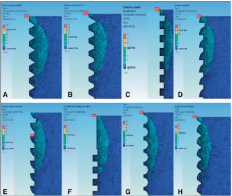
In study 4, the finite element analysis of the prototype test and control implant design showed, that the stress levels were in the range was 0.28 Mpa to 62Mpa for the control implant model design, where as it was in the range of 0.28 Mpa to 31Mpa for the test implant model (Fig 7).
In vivo
Surface topographical analysis
In study 2 and 3, the test and control prototype implants were confirmed to have a smooth surface, i.e. <0.5 lm in average height deviation, which is comparable to abutment surfaces. As there was no statistically significant difference of height deviation, the density, the ability to retain fluid (the Sci parameter) or the enlarged surface area between the two prototype implant design (Table 2). The roughness values for the valleys in between the V-shaped threads of the test implants presented significantly higher values than other parts, however, they were still smooth. Thus, the influence of micrometer structures was negligible.
In study 4, similarly, the test and control implant samples were both found to have a smooth surface i.e < 0.5um in average height deviation, even though they were having the oxidized surface. There was no statistically significant difference between the two-implant design regarding their height deviation, the density, the ability to retain fluid (the Sci parameter) or the enlarged surface area (Table 2).
ITQ and RTQ results
In study 2, the mean values of the ITQ measured by the ITQ device for the control and test groups in the tibia were 15 and 20 Ncm respectively,and in the femur, the values were 11 and 12 Ncm, respectively. The mean RTQ values measured by the RTQ device for the control and test groups in the tibia were 7 and 9 Ncm, respectively, and in the femur, 7 and 7 Ncm, respectively. As most of the mean values were higher for the test group, the statistical analysis presented statistically significant differences between control and test implants for ITQ and RTQ in tibia and RTQ of femur, whereas there was no significant difference between control and test group for Femur ITQ (Table 6,7,8).
Table 6. Insertion torque values of the study implants in rabbits. (Study 2)
Rabbit no. Tibia(control) Femur(control) Tibia (Test) Femur (Test)
1. 35.9 6.0 41.5 14.1 2. 13.3 13.0 16.1 16.3 3. 28.0 14.5 24.7 9.5 4. 1.7 3.1 9.7 3.5 5. 32.3 16.0 19.7 12.8 6. 13.2 13.5 13.1 7.2 7. 1.9 23.5 20.1 11.7 8. 10.0 3.2 16.9 20.4 9. 1.5 12.8 27.0 18.5 10. 19.2 12.1 16.8 14.4 Mean 15.7 11.8 20.6 12.8 Median 13.25 12.9 18.3 13.45 Standard Deviation 12.88 6.2 8.9 5.1
Table 7. Removal Torque values of the study implants at 4 weeks of time. (Study 2)
Rabbit Tibia (Control) Ncm Femur(control) Ncm Tibia (test) Ncm Femur(test) Ncm 1 4 4 7 11 2 7 7 17 9 3 14 14 14 11 4 6 6 5 5 5 17 17 12 11 6 9 9 5 7 7 7 7 12 3 8 4 4 7 5 9 5 5 4 5 10 6 6 8 10 Mean 7.9 7.9 9.1 7.7 STDV 4.3 4.3 4.4 3.1