SKI Report 2003:05
Research
Mechanical Integrity of Copper Canister
Lid and Cylinder
Marianne Karlsson
January 2002
ISSN 1104–1374 ISRN SKI-R-03/05-SE
SKI perspective
Background and purpose of the project
The integrity of the canister is an important factor for long-term safety of the repository for spent nuclear fuel. The mechanical integrity of the canister might be affected by different degradation mechanisms. Depending on different conditions i.e. loading intensity, loading mode and temperature etc, different degradation mechanisms can have a possible harmful effect on the mechanical integrity of the copper canister. The purpose of this project was to get an understanding of which degradation mechanism are most interesting, with regard to their harmful effect on the canister, by using simple calculation methods (FEM).
The calculations are made using the conditions in the repository and the canister design (presented by SKB) as boundary data.
Results
The most important conclusion is that in spite of the compression loads, the outer surface of the copper canister and the lid will be affected of tensile stresses. In presence of tensile stresses on the outer surface of the canister, stress corrosion cracking cannot be ignored and has to be taken care of in the canister lifetime calculations.
A sensitivity analysis is also performed to clarify the effect of design and creep parameters. Results of this analysis will be reported separately.
Effects on SKI work
The study will be a basis for coming SKI research projects and SKI reviews of SKB’s RD&D-programme.
Project information
Responsible for the project at SKI has been Behnaz Aghili. SKI reference: 14.9-010574/01107.
SKI Report 2003:05
Research
Mechanical Integrity of Copper Canister
Lid and Cylinder
Marianne Karlsson
Semcon Research and Development AB
Box 5028
SE-121 05 Johanneshov
Sweden
January 2002
SKI Project Number 01107
This report concerns a study which has been conducted for the Swedish Nuclear Power Inspectorate (SKI). The conclusions and viewpoints presented in the report are those of the author/authors and do not necessarily coincide with those of the SKI.
i
Summary
This report compiles finite element analyses performed to ensure the structural integrity of canisters used for storing of nuclear fuel waste of type BWR. The report comprises analyses performed on the canister lid and cylinder casing in order to determine static and long-term strength of the structure. The analyses are originally performed by Gert Herdner, SKI and subsequently supplemented by Semcon.
Finite element analyses compiled in this report are listed under Reference 1.
The numerical finite element calculations on the canister complement analytical estimates [2] and are performed in order to identify areas that may be of interest when reviewing the integrity of the copper canister.
The report analyses the mechanical response of the lid and flange of the copper canister when subjected to loads caused by pressure from swelling bentonite and from ground water at a depth of 500 meter. The loads acting on the canister are somewhat uncertain and the cases investigated in this report are possible cases. Load cases analysed are:
• Pressure 15 MPa uniformly distributed on lid and 5 MPa uniformly distributed on cylinder. • Pressure 5 MPa uniformly distributed on lid and 15 MPa uniformly distributed on cylinder. • Pressure 20 MPa uniformly distributed on lid and cylinder.
• Side pressures 10 MPa and 20 MPa uniformly distributed on part of the cylinder.
Creep analyses are also performed in order to estimate the stresses that will arise when the canister is placed in the repository.
The analyses in this report are recreated from the original analyses but the models differ in
geometry. Also, there is no information in the original reports on material data, time-independent as well as creep data, and analysis procedure. The data used in the recreated analyses are based on information from References 2, 3, 6 and 7.
The results presented in this report are based on the supplementary analyses. These results differ from the original results. Most likely this is due to differences in model geometry. The original results are appended to the report and are summarised for comparison with results from the supplementary analyses. Otherwise, these results are not further discussed.
Summary of results
For all load cases, high tensile stresses are found in the lid fillet between the planar part and the flange.
High tensile stresses are also found in the weld surface and on the outer side of the copper
cylinder, in the region from the weld down to the level of the insert. Since these stresses appear on the outside of the canister, a damage tolerance analysis of this region should be performed.
Tensile stresses appearing on the bottom of the lid are not likely to cause initiation of defects. Due to the magnitude of the stresses, the region should however be assessed regarding growth of existing defects.
In a modified design, the lid is fitted in the copper cylinder with zero gap as opposed to the original design where there is a gap of 1 mm between the lid and cylinder. The peak tensile
stresses caused by two critical load cases thus shift from the weld region to a region further down. Stresses in the order of magnitude of the yield strength do not appear until approximately 30 mm below the weld. This may be advantageous if the weld and the region in the vicinity of the weld are considered to be most critical as regards high tensile stresses.
ii
Contents
Summary ___________________________________________________________i
Contents___________________________________________________________ ii
1 Introduction_____________________________________________________ 1
2 Geometry _______________________________________________________ 1
3 Material ________________________________________________________ 3
3.1 Time-independent elastic-plastic properties 3
3.2 Creep properties 3
4 Load cases ______________________________________________________ 4
5 Design Criteria __________________________________________________ 6
6 Finite Element Analysis ___________________________________________ 6
6.1 Software 6
6.2 Finite element model 6
6.2.1 Model 6 6.2.2 Contact 6 6.2.3 Boundary conditions 10 6.3 Analysis procedure 10 6.3.1 Static analysis 10 6.3.2 Creep analysis 10 6.4 Limitations 10
7 Results ________________________________________________________ 10
7.1 Summary of results 12 7.2 Design 1 137.2.1 Axisymmetric load cases 13
7.2.2 Side load 15
7.3 Design 2 16
8 Discussion _____________________________________________________ 16
9 Conclusions ____________________________________________________ 17
10 References _____________________________________________________ 18
Appendices
A Summary of current and original analyses__________________________ 19
B Load case 1 — Lid 15 MPa, cylinder 5 MPa _________________________ 24
B.1 Contact 24
B.2 Stress 24
B.3 Strain 28
C Load case 2 — Lid 5 MPa, cylinder 15 MPa _________________________ 29
C.1 Contact 29
C.2 Stress 30
C.3 Strain 33
D Load case 3 — Uniform pressure on canister ________________________ 34
D.1 Contact 34
D.2 Stress 35
D.3 Strain 38
E Creep — Axisymmetric load______________________________________ 39
E.1 Contact 39
E.2 Stress 40
E.3 Strain 43
F Load case 4 — Side load _________________________________________ 44
F.1 Stress 44
F.2 Strain 46
F.3 Radial displacement 47
G Creep — Side load 10 MPa _______________________________________ 48
G.1 Stress 48
G.2 Strain 50
G.3 Radial displacement 52
H Design 2 _______________________________________________________ 53
H.1 Static analysis — Load case 1 and 2 53
H.2 Creep — Load case 1 65
I Results from originally performed analyses_________________________ 69
I.1 Load case 1 71
I.2 Load case 2 76
I.3 Load case 3 81
I.4 Creep—Axisymmetric load 86
1
1 Introduction
The canister used for storing nuclear fuel waste of type BWR consists of an inner part (insert) of ductile cast iron and an outer part of copper. The copper canister is to provide a sealed barrier between the contents of the canister and the surroundings.
This report compiles finite element (FE) analyses performed to ensure the mechanical integrity of canisters used for storing of nuclear fuel waste. The objective is to determine static and long-term strength of the canister lid and flange. The original FE analyses are performed by Gert Herdner, SKI, and the supplementary performed analyses also presented in this report are based on these original analyses.
The FE calculations complement analytically performed estimates [2]. The analyses are performed in order to identify areas that may be of interest when reviewing the integrity of the copper canister.
The report analyses the mechanical integrity of the lid and flange of the copper canister for the load cases:
• Uniformly distributed outer pressure
• Different pressure for the upper part of the lid and for the copper cylinder • Side pressure acting on a part of the cylindrical shell
Two designs, differing in initial gap distance between the copper lid and cylinder, are analysed. The analyses are initially performed on design 1, where the gap distance is 1 mm. Results from these analyses proved not acceptable why analyses also are performed on a design with zero gap between lid and cylinder. This design is more advantageous regarding high stresses in critical regions.
The recreated analyses in this report are performed on models that differ in geometry from the models used in the originally performed analyses. Geometrical dimensions were not determined at the time the original analyses were performed, and it is not possible to retrieve the data used for these analyses. Also, there is no information in the original reports on material data, time-independent as well as creep data, and analysis procedures. The data used in the recreated analyses are based on information from References 3-6 and are outlined in subsequent sections.
2 Geometry
The region analysed is shown in Figure 1. For more details about the analysed design, see
References 2 and 6.
The design of the copper canister was not definite and geometrical dimensions were not determined at the time the original analyses were performed. A preliminary design
proposal of the canister was used and it is not possible to retrieve the data used. Estimates on dimensions, however, are shown in Appendix A.
Two designs, differing only in initial gap distance between the lid and copper cylinder, are evaluated.
The dimensions used for the supplementary analyses are based on data from References 2-6 and are shown in Figure 2. The initial gap between lid and insert as well as the initial radial gap between the copper cylinder and the insert is 4 mm [2,6]. In design 1, the gap between
the lid and the copper cylinder is initially 1 mm [2,6], while in design 2 there is zero initial gap between lid and cylinder.
3
3 Material
3.1 Time-independent elastic-plastic properties
The material in the canister is copper with the following properties:
Young’s modulus: E =114 GPa
Poisson’s ratio: ν=0.35
Yield strength: σs=50MPa
The plastic properties are modelled using a bi-linear material model [2]. The plastic
deformation is assumed to follow von Mises yield law and isotropic hardening. The plastic modulus is assumed to be 1/100 of the elastic Young’s modulus, i.e.
Ep=E/100=114/100=1.14 GPa
Figure 3 compares the stress-plastic strain relationship according to SKB TR 92-30 with the
bi-linear stress-plastic strain relationship used in the current analysis. The difference between the two is small for plastic strains up to 10% or stresses up to 164 MPa [2].
Figure 3 Comparison of the plastic strain relationship according to SKB TR92-30 [8] and the bi-linear
stress-plastic strain relationship used in this analysis [2].
3.2 Creep properties
According to Reference 2, the long-term creep properties for copper at 100°C are not well known. The longest creep tests that have been carried out are 19 900 hours, i.e. less than 2.5 years. Extrapolating the creep behaviour for time periods exceeding 100 years thus is not reliable and all predictions for times beyond 10 000 years are associated with great uncertainties. A listing of the estimates of secondary creep shows that the uncertainty is great [2].
Analyses performed in this report assumes a secondary creep rate of 1% for 100 years at a temperature of 100°C and a stress level of 100 MPa, and a linear stress dependency
according to [2]: n k dt d ⋅ = 0 σ σ ε where: k=1⋅10-4 1/year σ0=100 MPa n=1
4 Load cases
Loads analysed in this report are swelling pressure from the bentonite and hydrostatic pressure from the ground water.
The canister is placed in a hole in the bedrock, where it will be surrounded by a couple of decimetres of compacted bentonite clay. When the bentonite becomes saturated with water it expands and fills any gaps in the bentonite buffer. The bentonite will exert a pressure of maximum 10 MPa on both the bedrock and the canister [2,7].
This report assumes that the canister will be deposited at a depth of 500 m. The hydrostatic pressure caused by the ground water on the canister thus is 5 MPa.
An outline and discussion of possible loads are found in Reference 2 and 7. The loads acting on the canister are somewhat uncertain. The swelling pressure from the bentonite may vary substantially over time and, depending on how the watering of the bentonite is done, the swelling may induce uneven pressure on the canister. Possible load cases are handled in this report.
The analyses in this report consider three loading conditions:
• axisymmetric outer pressure that varies between lid and cylinder • uniform outer pressure
• side pressure on part of the canister.
The load cases are listed in Table 1. Cases 1 to 3 are axisymmetric loads and case 4 is a side pressure applied on half of the cylinder casing. Regions A-C refer to axisymmetric regions and region D is symmetric in the x-z plane (about the x-y plane). Load cases will
hereinafter be referred to by their load case number. Creep analyses are performed for load case 1 and for a side pressure (load case 4). In the latter case, the creep analysis is performed for a side pressure of 10 MPa.
Table 1 Load cases. See Figure 4 and 5 for reference regions A-D.
Load case Lid Lid flange top Lid outer flange
and cylinder
Lid outer flange and cylinder
1 Static/
creep 500 yrs 15 MPa 5 MPa 5 MPa 2 Static 5 MPa 5 MPa 15 MPa
5
Figure 4 Outer pressure on lid and cylinder casing. Axisymmetric load cases.
Figure 5 Outer pressure on lid and cylinder. Side load on half of the copper cylinder. y x z D C B A
5 Design Criteria
Design criteria for the copper canister are referenced and discussed in Reference 2 and 7. Maximum principal stresses are of interest since initiation and growth of cracks (stress corrosion, stable and unstable crack growth) can take place in areas where tensile principal stresses are large. Damage tolerance analyses therefore should be performed in order to assess the risk for crack initiation and crack propagation. This is not done within the scope of this report. The creep strains are of interest since the creep ductility of copper in certain environments has proved to be low. Furthermore, deformations are of interest since large deformations may lead to thickness reductions of the canister causing the sealing margins for the copper canister to become to low [2,7].
6 Finite Element Analysis
6.1 Software
I-DEAS is used for modelling the geometry and for applying boundary conditions and loads. Abaqus is used for the finite element analyses. Post-processing of results is done using I-DEAS.
6.2 Finite element model
6.2.1 ModelThe lid and cylinder casing are in the axisymmetric case modelled using axisymmetric solid elements (Abaqus type CAX4). Figure 6 and 7 show the finite element (FE) model of design 1 and Figure 8 shows the FE mesh of design 2. In the case where a side load is applied on part of the canister the canister is modelled using 3D brick elements (Abaqus type C3D8 and C3D6), see Figure 9 and 10.
The axisymmetric model of design 1 consists of 383 elements and 446 nodes, yielding a total of 1338 degrees of freedom. Corresponding figures for design 2 is 485 elements, 552 nodes and 1656 degrees of freedom.
The three-dimensional (3D) model is modelled using 681 elements and 913 nodes, yielding a total of 2739 degrees of freedom. Gap elements are red in Figure 7 and 9.
6.2.2 Contact
Contact between lid and insert and between lid and cylinder casing are modelled using GAP elements (Abaqus type GAPUNI).
Each GAP element is connected to a pair of nodes and is given a specified initial distance. During analysis, the relative displacement between the connected nodes will determine whether the nodes are in contact.
For design 1, the initial distance is specified to 1 mm. For design 2 the initial distance is 0 mm, i.e. there is no gap between the nodes.
7
Friction between the copper lid and the insert and between copper cylinder and insert do not significantly affect the resulting stresses. In the calculations of design 2, the following friction coefficients are assumed, as they are considered conservative regarding stresses at the weld surface:
Copper – copper: µ1 =0.15
Copper – cast iron: µ2 =0.3
Figure 6 Axisymmetric FE model used in the axisymmetric analyses (load case 1-3). y
Figure 7 FE model in the transition region between lid and copper cylinder. Red elements are GAP contact elements.
Figure 8 Local FE mesh of the design 2. The initial zero gap between lid and cylinder is specified in the GAP element
9
Figure 9 3D finite element model used in analysing a side load (load case 4).
Figure 10 Local mesh in the 3D model.
y
x z
6.2.3 Boundary conditions
Both the axisymmetric and the 3D finite element model are restrained not to translate in the tangential direction (z-direction in Figure 6 and Figure 9). In the first case due to axisymmetry and in the latter due to symmetry about the x-y plane. The bottom of the cylinder casing is restrained in axial translation.
To ensure that the stresses in the lid-cylinder transition region is undisturbed by applied boundary conditions, a sufficiently large part of the copper cylinder (1105 mm) is included in the model.
6.3 Analysis procedure
6.3.1 Static analysisThe static analyses consider elastic-plastic material behaviour. The behaviour is modelled with a bi-linear material model (see Section 3.1) where the plastic deformation is assumed to follow von Mises yield law and isotropic hardening. The analyses account for geometric non-linearity.
6.3.2 Creep analysis
In the creep analyses the load is applied in one step that considers the elastic-plastic behaviour of the material and geometric non-linearity. The load is kept at that level in the second step where the creep behaviour is analysed. Creep data according to Section 3.2 is applied.
6.4 Limitations
The analyses in this report are recreated from the original analyses but the models differ in geometry. Also, there is no information in the original reports on material data, time-independent as well as creep data, and analysis procedure. The data used in the recreated analyses are based on information from References 2, 3 and 6 and are outlined in preceding sections.
The models used in the analyses are quite coarse and the analyses are intended to give an estimate of areas that may cause problems regarding stresses and deformations that appear due to the various possible cases of external pressure.
7 Results
Results discussed in this section are based on the supplementary analyses performed on design 1 and 2. Regions specifically analysed are the lid fillet region, the weld between lid and casing and the outside of the cylinder casing from the weld down to the level of the insert. Regions are shown in Figure 11.
The results are summarised in Section 7.1 and Appendix A. Referenced elements are shown in Figure 11-13. Details on results for each load case considered are presented in Section 7.2 and 7.3.
11
Results from the original finite element analyses are summarised and compared to results from the supplementary analyses in Appendix A. Original result figures are presented in
Appendix I. Otherwise, these results are not further commented in this section.
Figure 11 Elements in the lid/cylinder transition region for axisymmetric analyses (load cases 1-3). Design 1.
Figure 13 Design 2. Regions specifically analysed are the lid fillet, the weld region and the outside of the cylinder. The
region referred to as the weld region includes the weld surface and root, and the region in the vicinity of the weld.
7.1 Summary of results
Resulting maximum stresses and strains for all load cases and both designs are
summarised in Table 2 and Table 3. Generally, the two designs differ regarding tensile stresses on the outside of the cylinder, in the region from the weld down to the level of the insert. In design 1, high tensile stresses are concentrated to the weld region while in design 2 the peak stresses appear further down, in a region closer to the level of the insert. The stress level is however not affected. Tensile stresses in the lid fillet are high and increase by approximately 10% from design 1 to design 2. Plastic strains and creep strains are in the same order of magnitude between the two designs.
For all load cases where pressure is applied on both lid and cylinder, high tensile stresses are found in the lid fillet region. Maximum principal stress is 100 MPa for design 1 and appears for load case 1 during loading at a load fraction of 0.2. For design 2, the maximum tensile stress is 113 MPa and appears for both load case1 and 2.
The stresses in the weld are mainly compressive. Tensile stresses appear in the weld surface and root where the maximum principal stress for design 1 is above the yield limit (load case 1 and 2). Design 2 shows lower stresses in this region; maximum tensile stress is 29 MPa. Stresses just above the yield limit appear approximately 30 mm further down along the copper cylinder. Maximum principal plastic strain caused by tensile stresses is in the order of 2.6%. Plastic strain on the inner side of the casing (element 952) is caused by compressive stresses.
On the outside of the cylinder casing, from the weld down to the level of the insert, high tensile stresses are for design 1 found (elements 951-1058) for several of the calculations. The high stresses are concentrated to a region close to the weld (element 951) and at the level of the insert (element 226). Maximum principal stress in the latter region is 71 MPa
13
Plastic strains due to tensile stresses are less than 2.6%. Creep strains due to tensile stresses for the axisymmetric load cases are less than 2.8%. When a large side load is applied for a long period of time, the strain becomes in the order of 6%.
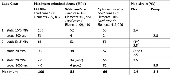
Table 2 Summary of resulting maximum tensile stresses and strains for analysed load cases. Supplementary analyses
on design 1.
Load Case Maximum principal stress (MPa) Max strain (%)
Lid fillet Load case 1-3: Elements 785, 852 Weld surface Load case 1-3: Elements 959, 951 Load case 4: Element 409, 410 Cylinder outside Load case 1-3: Elements -1058 Load case 4: Elements 413-226 Plastic Creep 1 static 15/5 MPa creep 500 yrs 100 51 52 4 55 2 2.4 2.8 2 static 5/15 MPa 85 53 53 (3*) 2.5 3 static 20 MPa 96 48 52 (3.5*) 2.5 4 static 20 MPa creep 1000 yrs <0 <0 34 (root) 6 (root) 66 52 2.6 5.5 Maximum 100 53 66 2.6 5.5
* Strains are due to compressive stresses in the regions.
Table 3 Resulting maximum tensile stresses and strains for supplementary analyses on design 2. Results are
summarised for a friction coefficient µ =0.15 between lid and copper cylinder.
Load Case Maximum principal stress (MPa) Max strain (%)
Lid fillet
Elements 6, 9 Weld surfaceElements 41, 45-46 Cylinder outside Elements 46-432 Plastic Creep 1 static 15/5 MPa creep 500 yrs 113 51 15 5 55 5 3.5 2.5 2 static 5/15 MPa 113 29 45 3.2 Maximum 113 29 55 3.5 2.5
7.2 Design 1
7.2.1 Axisymmetric load cases
Results for the axisymmetric loads are shown in Appendix B-D. Load case 1
Result figures and graphs for load case 1 are shown in Appendix B.
Maximum principal stress in the lid fillet is 100 MPa and appears at a load fraction 0.2. The stresses remain relatively constant for increasing pressure. Max principal plastic strains are less than 2.4%.
For load case 1 there is no contact between the lid lower edge and casing to relieve the weld at the surface (element 951) why high tensile stresses are concentrated to this region.
Maximum principal stress at the weld surface is 52 MPa. Stresses in the weld are otherwise compressive. Strains are negligible.
Maximum principal stress on the cylinder outside is 55 MPa. Strains are negligible. As an increasing part of the lid and the cylinder come into contact with the insert, tensile stresses appear in the lid. Maximum tensile stress in the lid bottom is approximately 90 MPa and at the inner side of the cylinder between 40 and 50 MPa.
Load case 2
Result figures and graphs for load case 2 are shown in Appendix C.
The lid lower edge and the copper cylinder come in contact at a load fraction 0.47 causing some of the load to be transferred at the contact point instead of the weld. As contact is established, the lid fillet and the weld will be relieved to some extent as seen in the result figures. Only the weld surface and root show tensile stresses.
The max principal stress in the lid fillet, approximately 85 MPa at load fraction 0.47, decreases with increasing load. At load fraction 0.85, the stresses have decreased to a level below the yield limit. Plastic strains at full load are negligible.
Weld maximum tensile stress, 53 MPa, appears at load fraction 0.5. Weld peak tensile stresses appear at the surface and decrease as the lid lower edge and the cylinder come in contact. Plastic strains appearing in element 952 are due to compressive stresses.
In the cylinder casing, except in the weld region, stresses are below the yield limit. Max principal plastic strains are negligible.
Tensile stresses due to bending in the lid bottom and at the inner side of the cylinder are lower than 45 MPa.
Stresses and plastic strains appearing in the contact region between the lid lower edge and the copper cylinder are not reliable. The contact is modelled as discrete points while
contact actually is distributed over a continuous area. Thus, stresses and strains are likely to be lower than the ones appearing in this analysis.
Load case 3
Result figures and graphs for load case 3 are shown in Appendix D.
The lid lower edge and the copper cylinder come into contact at a load fraction 0.3.
The max principal stresses in the lid fillet, approximately 95 MPa, appear at a load fraction 0.1. The stresses decrease with increasing load. At load fraction 0.45, the stresses have decreased to a level below the yield limit. Plastic strains at full load are negligible.
Weld maximum tensile stress, below 50 MPa, appears at the weld surface. Max principal stresses initially increase with increasing load and are then kept at a relatively constant level. Plastic strains appearing in element 952 are due to high compressive stresses. In the cylinder casing, max principal stresses are just below the yield limit. Stresses in the region below the weld (element 955 and 956) peak at approximately 53 MPa for a load fraction of 0.35. Max principal plastic strains are negligible at 15 MPa.
15
Creep
A creep analysis is performed for load case 1. Result figures and graphs for the analysis are shown in Appendix E.
During the initial loading, the lid lower edge and the cylinder casing do not come in contact, but after approximately 10 years of creep contact is established.
The initially high stresses in the lid fillet region are relaxed. In the fillet region the stresses decreases from initially 100 MPa to 55 MPa after 200 years and is then kept at a relatively constant level.
The stresses in the weld are compressive except on the outer surface. The tensile principal stresses in the weld in this region decreases from 55 MPa to approximately 5 MPa after 100 years and is then kept relatively constant.
The highest creep strains appear in this region. Maximum principal strain after 500 years is approximately 2.8%.
Tensile stresses due to bending in the lid bottom and at the inner side of the cylinder are also relaxed. The stress level is between 10 and 20 MPa.
7.2.2 Side load
Result figures and graphs for load case 4, side pressure, are shown in Appendix E-F. Static load
Tensile stresses are initially high in the inner part of the weld; maximum principal stress is approximately 82 MPa, but decreases with increasing load. At a side pressure of 20 MPa, the tensile stresses have stagnated at approximately 12 MPa. Stresses at the weld surface are compressive.
At the outer side of the cylinder casing, stresses close to the weld (in elements 410 and 413) are compressive while stresses at the level of the lid lower edge are tensile. Max principal stresses in this region are relatively constant at approximately 66 MPa.
Bending stresses are high in the copper cylinder. Maximum von Mises stress is approximately 90 MPa.
Creep
A creep analysis is performed for a side load of 10 MPa. Result figures and graphs for the analysis are shown in Appendix F.
Max principal stresses increases to 47 MPa after 1000 years. Max principal creep strains after 1000 years are 5.5% in this region.
Max principal stresses in the outer side of the copper cylinder decreases slowly from initially 60 MPa to 53 MPa after 1000 years. The maximum tensile stresses appear at the level of the lid lower edge (element 410). Max principal creep strains after 1000 years are approximately 5%.
7.3 Design 2
For design 1, tensile stresses are unacceptably high in the weld surface region on the outside of the cylinder why this region is specifically evaluated in the modified design. Since load case 1 and 2 proved to be the cases causing the most severe tensile stresses, these cases are used in the analysis of design 2.
Design 2, with zero gap between copper lid and cylinder, is analysed in terms of both static loading and creep. Results are summarised in Section 7.1 together with results for design 1. Result figures and graphs are shown in Appendix H.
The design shows better results regarding stresses in the weld region on the outside of the cylinder. Tensile stresses in the weld surface region and root are below the yield strength for both load cases. During static loading, the maximum tensile stress is less than 29 MPa, and after creep for 50 years, stresses on the weld surface are solely compressive. On the outside of the cylinder stresses in the magnitude of 50 MPa do not appear until
approximately 30 mm below the weld.
A zero-gap fitting of the lid is however not advantageous regarding stresses in the lid fillet region. Stresses in this region are not relieved. Maximum principal stress increases with approximately 10% compared to design 1, to 113 MPa. Plastic strains are high, maximum principal strain on the surface is 3.5%
These calculations are performed assuming a friction coefficient 0.15 between copper lid and cylinder. The results are affected by the friction; a low coefficient yield conservative results regarding the weld surface. Regarding stresses in the lid fillet, a low friction coefficient is advantageous. The affect of different friction coefficients is shown in
Appendix H.
8 Discussion
When the copper canister is subjected to the various cases of external pressure, the lid will partly come into contact with the insert causing tensile stresses in the lid bottom side. High tensile stresses appear on the lid bottom and the region with tensile stress increases with increasing load and time, as a larger part of the lid is pressed against the insert. As discussed in Reference 6, there is no known mechanism that will cause crack initiation on the inside of the canister; the material is assumed to be sufficiently ductile and defects from manufacturing cannot in absence of a corrosive environment propagate due to these stresses. Reference 6 also suggests that a crack propagation assessment be done when crack growth data for the material is available.
The gap between the lid lower edge and the cylinder casing (element 1109 in Figure 11) closes with increasing load for most load cases. For load case 1 there is no contact during the initial loading, contact is established after approximately 10 years. As also discussed in
Reference 6, contact between the lid and casing relieves the welded area, as some of the
load will be transferred at the contact point. The external pressure on the canister causes axial compression of the copper cylinder. Additionally, as the lid deforms, bending stresses will appear in the cylinder casing. Tensile stresses appear on the outside of the
17
relaxed during creep to 52 MPa (after 1000 years) and to 5 MPa (after 500 years),
respectively. As discussed in Reference 6, manufacturing defects in this region may, due to the state of strain and due to exposure to a corrosive environment, initiate crack growth. In design 2 the lid is fitted in the cylinder with zero gap in order to relieve the stresses in the welded region. The peak tensile stresses caused by load case 1 and 2 thus shift from the weld region to a region further down. Stresses in the vicinity of the weld thus become acceptable. This may be advantageous if the region at the level of the insert is considered less critical as regards high tensile stresses.
High principal stresses and strains appear in the lid fillet region. Peak tensile stress in this region is approximately 100 MPa and appears for load case 1. During creep, these stresses relax and after 200 years, the stresses are decreased to approximately 50 MPa. The high stresses and plastic strains as well as creep strains in this region suggest that a more
detailed analysis of this region be performed. The radius of the fillet will affect the stresses and strains appearing. The axisymmetric model has a radius of 3 mm, while the 3D model have no radius modelled. In addition, as suggested in Reference 6, the region should be assessed regarding crack propagation.
Fitting the lid in the cylinder with zero gap yields higher stresses in the fillet region. Uneven swelling of the bentonite is accounted for as a side load uniformly distributed along the height of the cylinder and lid flange. A possible case not considered in this report is an uneven distribution between the copper cylinder and the lid. Reference 2 estimates shear stresses in the copper cylinder for a case where a shear load is applied to the lid. The shear stresses thus appearing suggest that a numerical analysis considering plastic deformation and creep be performed.
9 Conclusions
For all considered load cases high principal stresses appear on the outside of the copper cylinder in the region from the weld down to the level of the lid lower edge. As suggested in Reference 6, a damage tolerance analysis should be performed to assess this region. In a design where the lid is fitted in the cylinder with no gap, the peak tensile stresses does not appear at the weld surface but further down. The level of maximum tensile stress is however not altered.
Tensile principal stresses also appear in the lid fillet region; particularly one load case causes high tensile stresses. The modification of the design does not significantly alter the resulting stresses. The state of strain in this region suggests that a more detailed analysis of this region be performed.
10 References
1 Result papers by Gert Herdner:
• Lock 15 MPa mantel 5 MPa elpl pålastning • Lock 15 MPa mantel 5 MPa elpl krypning • Lock 5 MPa mantel 15 MPa elpl pålastning • Lock mantel 20 MPa elpl pålastning
• Sidobelastning El-pl 20 MPa • Sidobelastning kryp, 1000 år
2 “Mechanical integrity of lid and cylindrical shell for the copper canister,” PM, SKI.
3 C-G Andersson, Test manufacturing of copper canisters with cast inserts, TR-98-09,
Swedish Nuclear Fuel and Waste Management Co, Stockholm, August 1998.
4 Drawing 00001-1111, Copper cylinder, BWR serial 1, rev 00, 970819.
5 Drawing 00001-31, Copper lid, BWR serial 1, rev 00, 970819.
6 “Creep stress analysis of the connection between the lid and the cylindrical shell of the
canister,” PM, SKI.
7 L Werme, Design premises for canister for spent nuclear fuel, TR-98-09, Swedish Nuclear
Fuel and Waste Management Co, Stockholm, September 1998.
APPENDIX A
19
A Summary of current and original analyses
Table 4 and Table 5 summarise and compare results from current (supplementary) and
original analyses.
There are differences between the results and the most noticeable differences appear on the outer side of the copper cylinder, especially for load case 1. In order to make it easier to see and also to draw conclusions as to why these differences exist, stress plots from
current and original analyses that also show deformations are presented side-by-side following the result tables.
As mentioned in Section 6.4, one obvious difference is the geometry. Other data (material
properties) do most likely not differ1 and thus are not likely to cause the differences in
results. An effort to estimate the geometry used in the original analyses is made in Figure
14. The dimensions are based on the assumption that the cylinder wall thickness is 50 mm. Figure 15 shows the geometry used in current analyses. As seen, there is one distinct
difference in the geometry, namely the height of the lid flange. The original lid has a higher flange, resulting in a weaker flange. The current stiffer design have the effect that contact between the lid lower edge and the cylinder (contact point 1109) for static load cases is either not established or established at a higher load. The difference in stiffness is more obvious when studying the creep behaviour, see Figure 17. The consequence is that the weld surface and the region in the vicinity of the weld are not relieved to the same extent as in the original weaker geometry.
Another distinction is the lid fillet radius. The smaller lid fillet radius in current analyses yields higher local stresses in the fillet region.
1 During the current analyses, possible alternative material data (in terms of yield strength and creep strain rate) have been used in an attempt to approach the original analyses as regards resulting stresses and strains and to interpret the differences in results. Conclusions from the analyses are that these alterations do not significantly affect the results, the behaviour of the model principally is the same.
APPENDIX A
Figure 14 Geometry used in original analyses. Dimensions are measured assuming a copper cylinder thickness of 50 mm. Figures are approximate. (mm)
Figure 15 Geometry used in supplementary analyses. Dimensions are based on data from Reference 2-5 and 7. (mm)
21
Table 4 Summary of resulting maximum tensile stresses for analysed load cases. Comparison between current (supplementary) and original analyses. If no load fraction is
specified, the stress appears at the final load.
Load Case Maximum principal stress (MPa)
Lid fillet Weld surface Cylinder outside
Current analyses Load case 1-3: Elements 785, 852 Original analyses Load case 1-3: Element 310, 311 Current analyses Load case 1-3: Element 951 Load case 4: 408-410 Original analyses Load case 1-3: Element 341 Load case 4: Element 362 Current analyses Load case 1-3: Elements 955-1058 Load case 4: Elements 413-226 Original analyses Load case 1-3: Element 344-366 Load case 4: Element 363-365 1 static 15/5 MPa creep 500 yrs 100 51 98 80 52 4 6 6 55 2 2 2
2 static 5/15 MPa 85 (load 40%)
28 84 (load 47%)37 53 (load 55%)31 40 (load 40%)18 53 (load 55%)42 (load 100%) 41
3 static 20 MPa 96 (load 10%)
20 95 (load 10%)28 48 (load 35%)41 34 (load 32%)9 52 (load 35%)45 <035 (load 32%)
4 static 20 MPa creep 1000 yrs <0 <0 <0 <0 0 34 (root; load 15%) 81 (inside; load 15%) <0 6 (root) 47 (inside) <0 28 (root) 62 (inside) <0 72 (root) 72 (inside) 71 52 69 80 (100 yrs) 60 (1000 yrs) Maximum 100 98 53 34 (root) 81 (inside) 40 72 (root) 72 (inside) 71 80
Summary of resulting maximum plastic strains for analysed load
cases. Comparison between current and original analyses.
Load Case
Maximum principal strain (%) Plastic
Creep Current analyses Original analyses Current analyses Original analyses 1
static 15/5 MPa creep 500 yrs
2.4 (fillet) 2.3 (fillet) 2.8 (fillet) 4 (lid fillet) 2 static 5/15 MPa 1.6 (weld inside) 1 (fillet/weld inside) 3 static 20 MPa 3.5 (weld inside) 2 (fillet/weld inside) 4
static 20 MPa creep 1000 yrs
2.1 (cylinder outside) 2.6 (cylinder inside) 2.2 (cylinder outside) 5.2 (cylinder outside) 5.5 (weld inside) 7.4 (cylinder outside) Maximum 3 .5 (weld inside) 2 .3 (fillet) 5.5 (weld inside) 7.4 (cylinder outside)
23 949 37074. 891 43883. 833 50692. 775 57501. 717 64309. 659 71118. 601 77927. 543 84736. 485 91544. 427 98353. 370 05162. 312 11971. 254 18779. 196 25588. 138 32397. 803 9206. 224 6014. -354 7177. -934 0368. -151 33559. -209 26751. u tpu t S e t: Lock 1 5 ,m an tel 5 M P a e for m ed( 0. 00425 ):T ot al T rans lat ion on tour :S o lidMa x Pr inS tr es s Figure 16
Max principal stresses. Load case 1. Current anal
ysis on left (MPa) and original on right (Pa).
X Y Z 0. 03 9 1 0. 03 6 7 0. 03 4 2 0. 03 1 8 0. 02 9 4 0. 02 6 9 0. 02 4 5 0. 02 2 0. 01 9 6 0. 01 7 1 0. 01 4 7 0. 01 2 3 0. 00 9 8 1 0. 00 7 3 7 0. 00 4 9 2 0. 00 2 4 8 0. 00 0 0 3 4 5 V1 L1 C1 Ou tp u t Set :5 00 år De for me d (0. 00 7 8 5 ):To tal Tr an sl at ion Co n tou r:So lidC ree p St rai n Figure 17
APPENDIX B
B Load case 1 — Lid 15 MPa, cylinder 5 MPa
B.1 Contact
There is no contact between the lid and cylinder casing during loading.
B.2 Stress
APPENDIX B
25
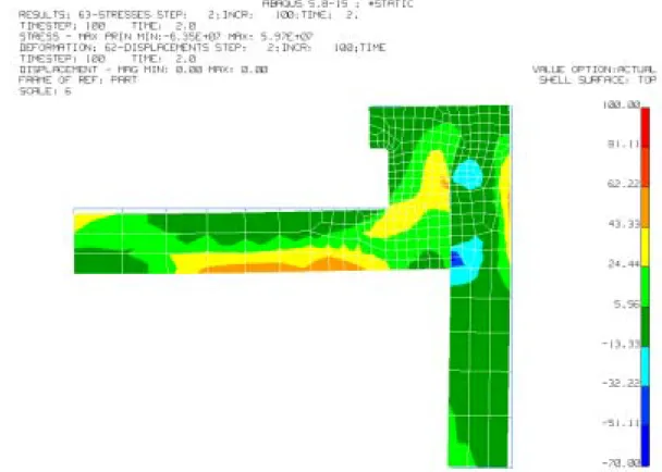
Figure 19 Max principal stresses (MPa). Load case 1 at a load fraction of 0.6.
APPENDIX B
Figure 21 von Mises stress (MPa). Load case 1.
0 10 20 30 40 50 60 70 80 90 100 0 0,1 0,2 0,3 0,4 0,5 0,6 0,7 0,8 0,9 1 Fraction of load St re ss , M P a Element 785 Element 852
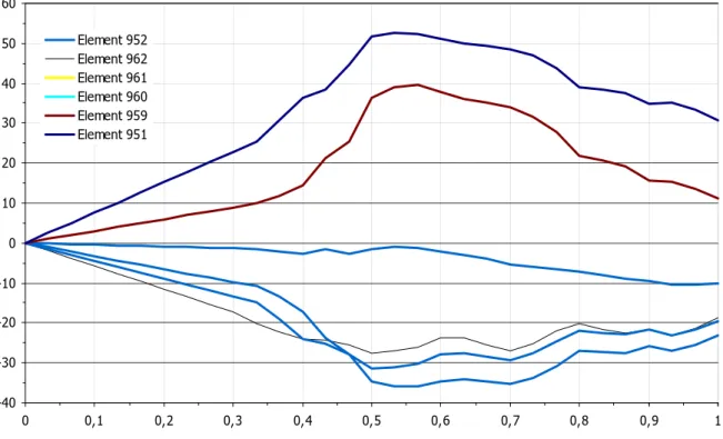
APPENDIX B 27 -30 -20 -10 0 10 20 30 40 50 0 0,1 0,2 0,3 0,4 0,5 0,6 0,7 0,8 0,9 1 Fraction of load St re ss , M P a Element 952 Element 962 Element 961 Element 960 Element 959 Element 951
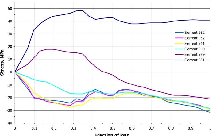
Figure 23 Max principal stress in weld during loading. Load case 1.
0 10 20 30 40 50 0 0,1 0,2 0,3 0,4 0,5 0,6 0,7 0,8 0,9 1 Fraction of load St re ss , M P a Element 951 Element 955 Element 956 Element 957 Element 958 Element 949 Element 1058
APPENDIX B
B.3 Strain
APPENDIX C
29
C Load case 2 — Lid 5 MPa, cylinder 15 MPa
C.1 Contact
0,00E+00 2,00E+05 4,00E+05 6,00E+05 8,00E+05 1,00E+06 1,20E+06 1,40E+06 0 0,1 0,2 0,3 0,4 0,5 0,6 0,7 0,8 0,9 1 Fraction of load Co n ta ct f o rc e, NFigure 27 Contact force between the lid lower edge and cylinder casing (element 1109 as shown in Figure 11) during
APPENDIX C
C.2 Stress
APPENDIX C
31 Figure 30 Max principal stress (MPa). Load case 2.
APPENDIX C 0 20 40 60 80 100 0 0,1 0,2 0,3 0,4 0,5 0,6 0,7 0,8 0,9 1 Fraction of load S tr e ss, M P a Element 785 Element 852
Figure 32 Max principal stress in lid fillet during loading. Load case 2.
-40 -30 -20 -10 0 10 20 30 40 50 60 0 0,1 0,2 0,3 0,4 0,5 0,6 0,7 0,8 0,9 1 Element 952 Element 962 Element 961 Element 960 Element 959 Element 951
APPENDIX C 33 0 10 20 30 40 50 60 0 0,1 0,2 0,3 0,4 0,5 0,6 0,7 0,8 0,9 1 Fraction of load St re ss , M P a Element 951 Element 955 Element 956 Element 957 Element 958 Element 949 Element 1058
Figure 34 Max principal stress in casing during loading. Load case 2.
C.3 Strain
APPENDIX D
D Load case 3 — Uniform pressure on canister
D.1 Contact
0,00E+00 2,00E+05 4,00E+05 6,00E+05 8,00E+05 1,00E+06 1,20E+06 1,40E+06 0 0,1 0,2 0,3 0,4 0,5 0,6 0,7 0,8 0,9 1 Fraction of load Co n ta ct f o rc e , NFigure 36 Contact force between the lid lower edge and cylinder casing (element 1109 as shown in Figure 11) during
APPENDIX D
35
D.2 Stress
Figure 37 Max principal stress (MPa). Load case 3: uniform loading of 5 MPa.
APPENDIX D
APPENDIX D 37 -40 -30 -20 -10 0 10 20 30 40 50 60 70 80 90 100 0 0,1 0,2 0,3 0,4 0,5 0,6 0,7 0,8 0,9 1 Fraction of load St re ss , M P a Element 785 Element 852
Figure 41 Max principal stress in lid fillet during loading. Load case 3.
-40 -30 -20 -10 0 10 20 30 40 50 0 0,1 0,2 0,3 0,4 0,5 0,6 0,7 0,8 0,9 1 Fraction of load St re ss , M P a Element 952 Element 962 Element 961 Element 960 Element 959 Element 951
APPENDIX D -10 0 10 20 30 40 50 0 0,1 0,2 0,3 0,4 0,5 0,6 0,7 0,8 0,9 1 Fraction of load S tr e ss, M P a Element 951 Element 955 Element 956 Element 957 Element 958 Element 949 Element 1058
Figure 43 Max principal stress in casing during loading. Load case 3.
APPENDIX E
39
E Creep — Axisymmetric load
E.1 Contact
0,00E+00 2,00E+05 4,00E+05 6,00E+05 8,00E+05 1,00E+06 1,20E+06 1,40E+06 0 50 100 150 200 250 300 350 400 450 500 Time, yrs Co n ta ct f o rc e , NFigure 45 Contact force between the lid lower edge and cylinder casing (element 1109 as shown in Figure 11) during
APPENDIX E
E.2 Stress
APPENDIX E 41 0 10 20 30 40 50 60 70 80 90 100 0 100 200 300 400 500 Time, yrs St re ss , M P a Element 785 Element 852
Figure 48 Max principal stress in lid fillet during creep 500 years. Load case 1.
-30 -20 -10 0 10 20 30 40 50 60 0 100 200 300 400 500 Time, yrs St re ss , M P a Element 952 Element 962 Element 961 Element 960 Element 959 Element 951
APPENDIX E -10 0 10 20 30 40 50 60 0 100 200 300 400 500 Time, yrs St re ss , M P a Element 951 Element 955 Element 956 Element 957 Element 958 Element 949 Element 1058
APPENDIX E
43
E.3 Strain
Figure 51 Max principal creep strains. Load case 1, creep 500 years.
0 0,01 0,02 0,03 0 100 200 300 400 500 Time, yrs C reep st rai n
Max principal strain element 785 Max principal strain element 852 von Mises strain Element 785 von Mises strain element 852
APPENDIX F
F Load case 4 — Side load
F.1 Stress
APPENDIX F
45
Figure 55 von Mises stress (MPa). Load case 4: side load of 20 MPa.
-20 -10 0 10 20 30 40 50 60 70 80 90 0 0,1 0,2 0,3 0,4 0,5 0,6 0,7 0,8 0,9 1 Fraction of load St re ss , M P a Element 408 Element 409 Element 410
APPENDIX F -20 -10 0 10 20 30 40 50 60 70 80 0 0,1 0,2 0,3 0,4 0,5 0,6 0,7 0,8 0,9 1 Fraction of load St re ss , M P a Element 410 Element 413 Element 416 Element 419 Element 226
Figure 57 Max principal stress in casing during loading. Load case 4: side load of 20 MPa.
APPENDIX F
47 Figure 59 Max principal strain. Load case 4: side load 20 MPa.
F.3 Radial displacement
-0,01 -0,009 -0,008 -0,007 -0,006 -0,005 -0,004 -0,003 -0,002 -0,001 0 0 0,1 0,2 0,3 0,4 0,5 0,6 0,7 0,8 0,9 1 Fraction of load Ra d ia l d is p la ce m e n t, mAPPENDIX G
G Creep — Side load 10 MPa
G.1 Stress
APPENDIX G
49
Figure 63 von Mises stress (MPa). Side load 10 MPa, creep 1000 years.
-10 0 10 20 30 40 50 60 0 100 200 300 400 500 600 700 800 900 1000 Time, yrs St re ss , M P a Element 408 Element 409 Element 410
APPENDIX G -10 0 10 20 30 40 50 60 0 100 200 300 400 500 600 700 800 900 1000 Time, yrs St re ss , M P a Element 410 Element 413 Element 416 Element 419 Element 226
Figure 65 Max principal stress in casing during creep for 1000 years. Load case 4
APPENDIX G
51
Figure 67 Max principal creep strain. Side load 10 MPa, creep 1000 years.
0 0,01 0,02 0,03 0,04 0,05 0,06 0,07 0 100 200 300 400 500 600 700 800 900 1000 Time, yrs C reep s tr a in
Max principal strain element 408 Max principal strain element 409 Max principal strain element 410
APPENDIX G 0 0,01 0,02 0,03 0,04 0,05 0,06 0 100 200 300 400 500 600 700 800 900 1000 Time, yrs Creep strain
Max principal strain element 410 Max principal strain element 413 Max principal strain element 416 Max principal strain element 419 Max principal strain element 226 von Mises strain element 419 von Mises strain element 226
Figure 69 Max principal creep strain and von Mises creep strain in casing during creep for 1000 years. Load case 4.
G.3 Radial displacement
-0,03 -0,02 -0,01 0 0 100 200 300 400 500 600 700 800 900 1000 R a dia l dis p la ce me n t, mAPPENDIX H
53
H Design 2
H.1 Static analysis — Load case 1 and 2
H.1.1 Contact 0,0E+00 2,0E+05 4,0E+05 6,0E+05 8,0E+05 1,0E+06 1,2E+06 0 0,1 0,2 0,3 0,4 0,5 0,6 0,7 0,8 0,9 1 Load fraction Co n ta ct f o rc e, NLoad case 1, friction Load case 1, no friction Load case 2
Figure 71 Contact force (N) between the lid lower edge and cylinder casing (element 627 as shown in Figure 13)
during loading. Load case 1 and 2. Contact for load case 1 is shown for a case where the friction coefficient µ=0.15 between lid and copper cylinder and for a case with no friction. For load case 2 µ=0.15 between lid and cylinder.
H.1.2 Stress
Stress plots are shown for load case 1 and 2, for load levels 20%, 60% and full load. Results
(figures and graphs) are shown for a friction coefficient µ=0.15 between copper lid and
cylinder. For load case 1, result figures are also shown for additional friction coefficients to depict the influence of sliding friction between lid and cylinder on the stress level.
Note that the scale on stress plots is linear between –20 MPa and 50 MPa only. Red areas indicate regions with stresses above 50 MPa.
APPENDIX H
Load case 1, µ=0.15 between lid and cylinder
Figure 72 Max principal stress (MPa). Load case 1 at a load fraction of 0.2.
APPENDIX H
55 Figure 74 Maximum principal stress (MPa). Load case 1.
Figure 75 von Mises stress (MPa). Load case 1.
APPENDIX H 0 10 20 30 40 50 60 70 80 90 100 110 120 0 0,1 0,2 0,3 0,4 0,5 0,6 0,7 0,8 0,9 1 Load fraction St re ss , M P a Element 6 Element 9
Figure 76 Maximum principal stresses in lid fillet during loading. Load case 1.
0 10 20 30 40 50 60 0 0,1 0,2 0,3 0,4 0,5 0,6 0,7 0,8 0,9 1 Load fraction St re ss , M P a Element 37 Element 41 Element 45 Element 46 Element 47 Element 48 Element 399
APPENDIX H 57 0 10 20 30 40 50 60 0 0,1 0,2 0,3 0,4 0,5 0,6 0,7 0,8 0,9 1 Load fraction S tr e ss, M P a Element 409 Element 410 Element 411 Element 412 Element 413 Element 400 Element 432
Figure 78 Maximum principal stresses on cylinder outside during loading. Load case 1.
Load case 2, µ =0.15 between lid and cylinder
APPENDIX H
Figure 80 Maximum principal stress (MPa). Load case 2 at a load fraction 0.6.
Figure 81 Maximum principal stress (MPa). Load case 2.
APPENDIX H
59 Figure 82 von Mises stress (MPa). Load case 2.
0 10 20 30 40 50 60 70 80 90 100 110 120 0 0,1 0,2 0,3 0,4 0,5 0,6 0,7 0,8 0,9 1 Load fraction St re ss , M P a Element 6 Element 9
APPENDIX H 0 10 20 30 40 50 60 0 0,1 0,2 0,3 0,4 0,5 0,6 0,7 0,8 0,9 1 Load fraction St re ss , M P a Element 37 Element 41 Element 45 Element 46 Element 47 Element 48 Element 399
Figure 84 Maximum principal stresses in weld region during loading. Load case 2.
0 10 20 30 40 50 60 0 0,1 0,2 0,3 0,4 0,5 0,6 0,7 0,8 0,9 1 Load fraction St re ss , M P a Element 409 Element 410 Element 411 Element 412 Element 413 Element 400 Element 432
APPENDIX H
61
Load case 1, varying friction coefficient between lid and cylinder
Figure 86 Maximum principal stress (MPa). Load case 1. Friction coefficient µ=0 between copper lid and cylinder.
0 10 20 30 40 50 60 0 0,1 0,2 0,3 0,4 0,5 0,6 0,7 0,8 0,9 1 Load fraction St re ss , M P a Element 37 Element 41 Element 45 Element 46 Element 47 Element 48 Element 399
Figure 87 Maximum principal stresses in weld region during loading. Load case 1. Friction coefficient µ=0 between
copper lid and cylinder.
APPENDIX H
Figure 88 Maximum principal stress (MPa). Load case 1. Friction coefficient µ=0.3 between copper lid and cylinder.
0 10 20 30 40 50 60 0 0,1 0,2 0,3 0,4 0,5 0,6 0,7 0,8 0,9 1 Load fraction St re ss , M P a Element 37 Element 41 Element 45 Element 46 Element 47 Element 48 Element 399
Figure 89 Maximum principal stresses in weld region during loading. Load case 1. Friction coefficient µ=0.3. 60 mm
APPENDIX H
63
Figure 90 Maximum principal stress (MPa). Load case 1. Friction coefficient µ=0.5 between copper lid and cylinder.
0 10 20 30 40 50 60 0 0,1 0,2 0,3 0,4 0,5 0,6 0,7 0,8 0,9 1 Load fraction St re ss , M P a Element 37 Element 41 Element 45 Element 46 Element 47 Element 48 Element 399
APPENDIX H
H.1.3 Strain
APPENDIX H
65
H.2 Creep — Load case 1
H.2.1 Contact 0,0E+00 2,0E+05 4,0E+05 6,0E+05 8,0E+05 1,0E+06 1,2E+06 0 100 200 300 400 500 Time, yrs Co n ta ct f o rc e , NAPPENDIX H
H.2.2 Stress
Figure 95 Maximum principal stress (MPa). Load case 1, creep 500 years.
0 10 20 30 40 50 60 70 80 90 100 110 120 0 100 200 300 400 500 Time, yrs St re ss , M P a Element 6 Element 9
APPENDIX H 67 0 10 20 30 40 50 60 0 100 200 300 400 500 Time, yrs St re ss , M P a Element 37 Element 41 Element 45 Element 46 Element 47 Element 48 Element 399
Figure 97 Maximum principal stresses in weld region during creep for 500 years. Load case 1.
0 10 20 30 40 50 60 0 100 200 300 400 500 Time, yrs St re ss , M P a Element 409 Element 410 Element 411 Element 412 Element 413 Element 400 Element 432
APPENDIX H
H.2.3 Strain
Figure 99 Maximum principal creep strain. Load case 1, creep 500 years.
0,000 0,010 0,020 0,030 0 100 200 300 400 500 Time, yrs C reep s tr a in
Max principal strain element 6 Max principal strain element 9 von Mises strain element6 von Mises strain element 9
APPENDIX I
69
I Results from originally performed analyses
X Y Z 304 303 297 295 316 312 324 324 312 320 314 313 316 315 317 319 318 310 308 311 233 235 299 309 301 232 234 302 300 290 292 291 293 304 303 298 296 294 297 295 580 58 V1 L1 C1
Figure 101 Elements in the lid fillet region for axisymmetric analyses.
X Y Z 366 347 346 345 344 341 268 561 581 583 590 589 587 305 304 303 297 295 289 316 312 573 572 323 322 312 320 314 313 316 315 321 317 319 318 310 308 311 307 233 235 237 239 299 309 301 232 236 238 234 302 306 300 290 292 284 285 291 293 286 287 304 303 296 298 305 281 294 288 297 295 289 336 282 562 580 582 584 588 586 283273 272 354 353 350 348 342 337 338 271 339 343 340 349 269 351 352 360 268 341 344 345 346 347 366 V1 L1 C1
APPENDIX I X Y Z 354 355 356 357 358 359 360 361 362 363 364 365 367 368 369 371 372 373 375 376 377 1 1 5
APPENDIX I
71
I.1 Load case 1
GeneralNo contact between the lid lower edge and casing to relieve the lid fillet. Fillet
Maximum principal stress is 98 MPa and remains relatively constant for increasing pressure.
Outer side of cylinder casing Stresses and strains are negligible. Weld
Mainly compressive stresses. Tensile stresses appearing at the surface are low. Strain
Maximum plastic strain 2.3 % appears in the lid fillet.
1.5E+7 1.5E+7 1.5E+7
5000000. 1.5E+7 5000000. 1.5E+7 1.5E+7 1.5E+7 1.5E+7 1.5E+7 5000000. 1.5E+7 1.5E+7 1.5E+7 1.5E+7 1.5E+7 1.5E+7 1.5E+7 1.5E+7 5000000. 1.5E+71.5E+7 1.5E+7 5000000. 1.5E+7 1.5E+7 5000000. 5000000. 1.5E+7 5000000. 5000000. 5000000.5000000. 5000000. 5000000.5000000.5000000. 5000000. 5000000.
Figure 104 Axisymmetric loading. Load case 1: pressure 15 MPa on lid inside and 5 MPa on lid top. Outer pressure 5
APPENDIX I 85670468. 81248776. 76827083. 72405391. 67983699. 63562007. 59140315. 54718623. 50296931. 45875239. 41453547. 37031854. 32610162. 28188470. 23766778. 19345086. 14923394. 10501702. 6080010. 1658317. -2763375. OutputSet:Lock3,mantel1MPa Deformed(0.00409):TotalTranslation Contour:SolidM ax PrinStress
Figure 105 Maximum principal stress (Pa). Load case 1 at 20% (lid 3MPa/cylinder 1 MPa) of final load. Maximum
stress 86 MPa appears in the fillet.
91669443. 86604887. 81540332. 76475776. 71411221. 66346665. 61282110. 56217554. 51152999. 46088443. 41023887. 35959332. 30894776. 25830221. 20765665. 15701110. 10636554. 5571999. 507443. -4557112. -9621668.
OutputSet:Lock 9,mantel3 MPa Deformed(0.00414):TotalTranslation Contour:SolidM ax Prin Stress
APPENDIX I 73 94937074. 89143883. 83350692. 77557501. 71764309. 65971118. 60177927. 54384736. 48591544. 42798353. 37005162. 31211971. 25418779. 19625588. 13832397. 8039206. 2246014. -3547177. -9340368. -15133559. -20926751.
OutputSet:Lock 15,mantel5 MPa Deformed(0.00425):TotalTranslation Contour:SolidM ax Prin Stress
Figure 107 Maximum principal stress (Pa). Load case 1 at final load (lid 15 MPa/casing 5 MPa). Maximum stress 95
MPa appears in the fillet.
0.0218 0.0207 0.0196 0.0185 0.0174 0.0164 0.0153 0.0142 0.0131 0.012 0.0109 0.00981 0.00872 0.00763 0.00654 0.00545 0.00436 0.00327 0.00218 0.00109 0.
OutputSet:Lock 15,mantel5 MPa Deformed(0.00425):TotalTranslation Contour:SolidPlasticStrain
APPENDIX I
1:SolidM ax PrinStress,Element310
2:SolidM ax PrinStress,Element311
0. 10000000. 20000000. 30000000. 40000000. 50000000. 60000000. 70000000. 80000000. 90000000. 0. 0.1 0.2 0.3 0.4 0.5 0.6 0.7 0.8 0.9 1. SetValue
Figure 109 Max principal stresses (Pa) in lid fillet. Load case 1.
2:SolidM ax PrinStress,Element344
3:SolidM ax PrinStress,Element345
4:SolidM ax PrinStress,Element346
5:SolidM ax PrinStress,Element347
6:SolidM ax PrinStress,Element366
0. 5000000. 10000000. 15000000. 20000000. 25000000. 30000000. 35000000. 40000000. 45000000. 0. 0.1 0.2 0.3 0.4 0.5 0.6 0.7 0.8 0.9 1. SetValue
APPENDIX I
75
1:SolidM ax PrinStress,Element338
2:SolidM ax PrinStress,Element339
3:SolidM ax PrinStress,Element340
4:SolidM ax PrinStress,Element341
-40000000. -30000000. -20000000. -10000000. 0. 10000000. 20000000. 30000000. 40000000. 0. 0.1 0.2 0.3 0.4 0.5 0.6 0.7 0.8 0.9 1. SetValue
Figure 111 Max principal stresses (Pa) in weld. Load case 1.
1:Gap X Force,Element562
0. 10000. 20000. 30000. 40000. 0. 0.1 0.2 0.3 0.4 0.5 0.6 0.7 0.8 0.9 1. SetValue
APPENDIX I
I.2 Load case 2
X Y Z 500000 500000 1.5E 500000 500000 1.5E 500000 500000 1.5E 1.5E 1.5E 1.5E 500000 1.5E 1.5E 500000 500000 500000 500000 500000 500000 500000 1.5E 500000 500000 500000 500000 1.5E 500000 500000 500000 500000 500000 500000 500000 1.5E 500000 500000 1.5E 500000 500000 500000 V1 L6 C1
APPENDIX I 77 X Y Z 63241044. 58844480. 54447916. 50051352. 45654788. 41258224. 36861660. 32465097. 28068533. 23671969. 19275405. 14878841. 10482277. 6085713. 1689150. -2707414. -7103978. -11500542. -15897106. -20293670. -24690234. V1 L6 C1 OutputSet:Lock 1,mantel3M Pa Deformed(0.00407):TotalTranslation Contour:SolidM ax Prin Stress
Figure 114 Maximum principal stresses (Pa). Load case 2 at 20% (lid 1 MPa/casing 3 MPa) of final load. Maximum
stress 86 MPa appears in the fillet.
X Y Z 65426875. 59649634. 53872394. 48095153. 42317913. 36540672. 30763432. 24986191. 19208951. 13431710. 7654470. 1877229. -3900011. -9677251. -15454492. -21231732. -27008973. -32786213. -38563454. -44340694. -50117935. V1 L6 C1 OutputSet:Lock 3,mantel9M Pa Deformed(0.00429):TotalTranslation Contour:SolidM ax Prin Stress
APPENDIX I X Y Z 41091446. 37194490. 33297533. 29400577. 25503620. 21606664. 17709707. 13812751. 9915794. 6018838. 2121881. -1775075. -5672032. -9568988. -13465945. -17362901. -21259858. -25156814. -29053771. -32950727. -36847684. V1 L6 C1 OutputSet:Lock 5,mantel15M Pa Deformed(0.00445):TotalTranslation Contour:SolidM ax Prin Stress
Figure 116 Maximum principal stresses (Pa). Load case 2.
X Y Z 0.0194 0.0185 0.0175 0.0166 0.0156 0.0147 0.0138 0.0128 0.0119 0.0109 0.00999 0.00905 0.0081 0.00716 0.00622 0.00528 0.00433 0.00339 0.00245 0.0015 0.000561 V1 L6 C1 OutputSet:Lock 5,mantel15M Pa Deformed(0.00445):TotalTranslation Contour:SolidPlastic Strain
APPENDIX I
79
1:Solid Max Prin Stress,Element310
2:Solid Max Prin Stress,Element311
0. 10000000. 20000000. 30000000. 40000000. 50000000. 60000000. 70000000. 80000000. 90000000. 0. 0.1 0.2 0.3 0.4 0.5 0.6 0.7 0.8 0.9 1. SetValue
Figure 118 Max principal stresses (Pa) in lid fillet during loading. Load case 2.
1:Solid Max Prin Stress,Element341
2:Solid Max Prin Stress,Element344
3:Solid Max Prin Stress,Element345
4:Solid Max Prin Stress,Element346
5:Solid Max Prin Stress,Element347
6:Solid Max Prin Stress,Element366
0. 5000000. 10000000. 15000000. 20000000. 25000000. 30000000. 35000000. 40000000. 45000000. 0. 0.1 0.2 0.3 0.4 0.5 0.6 0.7 0.8 0.9 1. SetValue
APPENDIX I
1:Solid Max Prin Stress,Element338
2:Solid Max Prin Stress,Element339
3:Solid Max Prin Stress,Element340
4:Solid Max Prin Stress,Element341
-40000000. -30000000. -20000000. -10000000. 0. 10000000. 20000000. 30000000. 40000000. 0. 0.1 0.2 0.3 0.4 0.5 0.6 0.7 0.8 0.9 1. SetValue
Figure 120 Max principal stresses (Pa) in weld during loading. Load case 2.
1:Gap X Force,Element562
0. 10000. 20000. 30000. 40000. 0. 0.1 0.2 0.3 0.4 0.5 0.6 0.7 0.8 0.9 1. SetValue
APPENDIX I
81
I.3 Load case 3
GeneralLoad up to 20 MPa.
Set value 0.1 = 2 MPa, 0.2 = 4 MPa, etc
The lid lower edge comes into contact with the cylinder at the pressure 6 MPa. Lid fillet
Element 310 (surface), 311 (10 mm from the surface)
Maximum tensile stress 95 MPa in the weld surface at approximately 6 MPa. Decreases with increasing load.
Outer side of casing
Element 341, 344 – 347, 366
Maximum stress in element is approximately 30 MPa. Large stress gradient towards the surface.
Maximum principal stress is 56 MPa at a node on the surface. Weld
Compressive stresses except at the weld surface (element 344). Strain
Plastic strain less than 2% at 15 MPa.
X Y Z
2.E+7 2.E+7 2.E+7 2.E+7 2.E+7 2.E+7 2.E+7 2.E+7 2.E+7 2.E+7 2.E+7 2.E+7 2.E+7 2.E+7 2.E+72.E+7 2.E+7 2.E+7 2.E+7 2.E+7 2.E+7 2.E+7 2.E+7 2.E+72.E+72.E+72.E+72.E+72.E+7 2.E+7 2.E+7 2.E+7 2.E+7 2.E+7 2.E+7 2.E+7 2.E+7 2.E+7 V1 L1 C1
APPENDIX I X Y Z 92107120. 86361305. 80615490. 74869675. 69123859. 63378044. 57632229. 51886414. 46140599. 40394784. 34648969. 28903154. 23157339. 17411524. 11665709. 5919894. 174079. -5571736. -11317551. -17063366. -22809181. V1 L1 C1 OutputSet:5 M Pa Deformed(0.00414):TotalTranslation Contour:SolidM ax Prin Stress
Figure 123 Max principal stresses (Pa). Load case 3: uniform pressure 5 MPa.
X Y Z 74333790. 68117203. 61900616. 55684029. 49467442. 43250855. 37034269. 30817682. 24601095. 18384508. 12167921. 5951334. -265253. -6481840. -12698427. -18915014. -25131601. -31348188. -37564775. -43781361. -49997948. V1 L1 C1 OutputSet:10 M Pa Deformed(0.00418):TotalTranslation Contour:SolidM ax Prin Stress