Research
Report number: 2012:49 ISSN: 2000-0456
Hydrogeological characteristics of
sites for low- and intermediate-level
waste disposal
2012:49
SSM perspective
Background
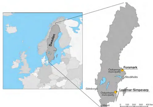
The Swedish Radiation Safety Authority (SSM) is responsible for the review of license applications for final repositories for low- and interme-diate-level radioactive waste (LILW). The Swedish Nuclear Fuel and Waste Management Co. plans to apply for an extension of the SFR facility in Forsmark to be able to dispose of decommissioning LILW. As a prepara-tion for this license applicaprepara-tion review SSM has commissioned a project to study the hydrogeological characteristics of some alternative sites for such a facility. An inland location in the Forsmark area and two sites in the Laxemar-Simpevarp area have been selected as potential alternative sites that are studied in this project.
Objectives
The objective of the study is to improve the knowledge on the controls on groundwater flow at selected potential alternative sites for a final reposi-tory for LILW. In particular, the aim is to compare these sites in terms of likely ranges of flow rates through depths of interest for a LILW facility, in terms of magnitude, predictability and uncertainties. Furthermore, the aim is to gather knowledge on the likely discharge areas and correspon-ding transport distances for groundwater passing through potential LILW facility locations, and how sensitive these are to changes in surface climate and relative sea level.
Results
The Forsmark area with its selected two sites and the Laxemar-Simpevarp area with its two sites are broadly similar in terms of lithology, rock ages, and tectonic histories. The two areas differ in terms of degree of deforma-tion, and tectonic fabric. Some lithologic and tectonic differences are noticeable between the two sites in the Forsmark area and between the two sites in the Laxemar-Simpevarp area.
These differences can be expected to influence hydrologic properties inclu-ding the magnitude and anisotropy of effective hydraulic conductivity on various scales. However, prediction of the consequences is dependent on complex fracture-network models, and these have not been presented at the same level of development or level of detail for all sites. In this study a simple evaluation of Darcy flux and transport resistance has been made for the sites. This evaluation indicates that the inland Forsmark-lens site has highest predicted fluxes and also the lowest minimum transport resistances, due to the very high horizontal hydraulic conductivity in the shallow bedrock. The simple evaluation also indicates that the Laxemar and Simpevarp sites have a lower minimum value of transport resistance than the Forsmark-SFR site; however, estimates are within roughly an order of magnitude.
Project information
2012:49
Author:Date: February 2012
Report number: 2012:49 ISSN: 2000-0456
Joel Geier
Clearwater Hardrock Consulting, Corvallis, U.S.A.
Hydrogeological characteristics of
sites for low- and intermediate-level
waste disposal
This report concerns a study which has been conducted for the Swedish Radiation Safety Authority, SSM. The conclusions and view-points presented in the report are those of the author/authors and do not necessarily coincide with those of the SSM.
Abstract
Hydrogeological circumstances are compared for four example locations in Sweden, focusing on factors that could be relevant for a disposal facility for short-lived, low-and intermediate-level radioactive waste (LILW). The four sites are:
SFR site at Forsmark (the proposed site for SFR expansion),
Forsmark tectonic lens (current candidate site for a spent-fuel repository), Laxemar (former candidate site for a spent-fuel repository), and
Simpevarp (former candidate site for a spent-fuel repository).
All four sites are coastal sites with low to moderate relief, and relatively thin, discontinuous Quaternary deposits overlying granitic bedrock of low per-meability which limits infiltration to the deep groundwater system. The two sites in the Forsmark area have relatively low relief and are undergoing relat-ively land rise. This implies a more dynamically evolving hydrologic situ-ation, with greater influence of both modern and relict marine waters, in comparison with the Laxemar-Simpevarp area.
Although broadly similar in terms in terms of lithology, rock ages, and tec-tonic history, bedrock in the Forsmark area differs from the Laxemar-Sim-pevarp area in terms of degree of deformation, and tectonic fabric. Litholo-gic and tectonic differences also are seen between each pair of sites in each of these areas. These differences influence patterns of deformation zones and smaller-scale fractures, and can be expected to influence hydrologic proper-ties including the magnitude and anisotropy of effective hydraulic conductiv-ity on various scales.
A simple evaluation of Darcy flux and transport resistance yields a conclu-sion that the Forsmark-lens site has the highest predicted fluxes and also the lowest minimum transport resistances, due to the very high horizontal hy-draulic conductivity in the shallow bedrock. This indicates that the
Forsmark-lens site would be the least optimal for a LILW disposal facility in the shallow bedrock, due to the high hydraulic conductivity of the shallow bedrock (in contrast to the deep bedrock). The Laxemar and Simpevarp sites compare favourably to the Forsmark-SFR site in terms of the minimum value of transport resistance, although estimates are within roughly an order of magnitude.
Content
1. Introduction...1 2. Site investigations...4 3. Surface conditions...7 4. Bedrock characteristics...16 5. Groundwater flow...40 6. Evaluation...47 7. Conclusions...53 8. References...551. Introduction
Background
Short-lived, low-and intermediate-level radioactive waste (LILW) from Swedish nuclear facilities is currently being sent to the SFR facility along the northern coast of Uppland, near the Forsmark nuclear power facility. The Swedish Nuclear Fuel and Waste Management Co. (SKB) has estimated that in addition to the space available in the current SFR, an additional 140,000 cubic meters of space will be needed to dispose of the volume of LILW that is expected to be generated in future decades, including operational waste and decommissioning waste from existing nuclear power plants.
One option under investigation is an expansion of the existing SFR, by adding a connected set of waste-disposal tunnels a short distance to the southeast of the facility (SKB, 2008b). As background for evaluating this choice of options for meeting the need for an expanded LILW disposal facil-ity, it is of interest to compare with other sites that could be considered. This research project compares hydrogeological circumstances among four example locations in Sweden for which comparable amounts of geoscientific information are available:
SFR site at Forsmark (the proposed site for SFR expansion),
Forsmark tectonic lens (current candidate site for a spent-fuel repository), Laxemar (former candidate site for a spent-fuel repository), and
Simpevarp (former candidate site for a spent-fuel repository, and location
of CLAB facility).
All four of these sites have been the focus of detailed site investigations and groundwater modelling studies by the Swedish Nuclear Fuel and Waste Management Co. (SKB). The first two are located near the Forsmark nuclear reactor site in the Östhammar municipality, while the last two are located near the Oskarshamn nuclear reactor site in Oskarshamn municipality. For the sake of brevity, the two sites in the Forsmark area are referred to herein collectively as the “Forsmark sites” and individually as “Forsmark-SFR” and “Forsmark-lens.” The Laxemar and Simpevarp sites are referred to collect-ively as the “Oskarshamn sites.”
Figure 1.1 Location of Forsmark and Laxemar-Simpevarp sites in Sweden (from SKB R-08-95, Figure 1-1).
Scope
The principal research questions addressed in this report are:
What are the fundamental controls on groundwater flow at these sites
(in-cluding geologic features influencing groundwater flow, topographic dif-ferences, surface climate, palaeohydrological impacts, and existing subsur-face facilities)?
How do the sites compare in terms of likely ranges of flow rates through
depths of interest for a LILW facility, in terms of magnitude, predictability and uncertainties?
What are the likely discharge areas and corresponding transport distances
for groundwater passing through potential LILW facility locations, and how sensitive are these to changes in surface climate and relative sea level?
All four of these sites have been the subject of hydrological and hydrogeolo-gical modelling using sophisticated computer models. Results from these modelling studies, in combination with a simple evaluation based on funda-mental hydrogeologic principles, are used as the basis for analysis, rather than entirely new, complicated site models.
Approach
The research questions outlined above are addressed by the following steps:
Literature survey to identify the most relevant site documents; Compilation of hydrological information from these sources; Simple evaluation of groundwater flow for each site
Evaluation of findings
The details of the literature survey have been documented in an earlier memorandum, and are not repeated in full detail here. The main results are documented by the list of references for this report (Chapter 8).
2. Site investigations
The Simpevarp, Laxemar, and Forsmark-lens sites have been investigated extensively as part of the Swedish spent-fuel repository programme. In gen-eral, the regional-scale results of investigations for the Forsmark-lens site are also relevant for the Forsmark-SFR site, which is within the regional-scale modelling area for the former.
Preliminary feasibility studies at these locations are given by (SKB, 2000a) and (SKB, 2000b). Simplified overviews of the subsequent investigations from 2002 through 2007 at Forsmark and Oskarshamn are given by (SKB, 2008c) and (SKB, 2008d).
Technically comprehensive descriptions of the investigations and their out-comes are given for Forsmark as (SKB, 2008e), for Laxemar as (SKB, 2009A), and for Simpevarp as (SKB, 2005a). In the case of Simpevarp, site investigations were terminated after a preliminary version of the site-de-scriptive model. The investigations for Forsmark and Laxemar were carried out fully to the point of producing site-descriptive models that could support a license application for a spent-fuel repository.
Ultimately, in March, 2011 a spent-fuel repository license application was submitted only for Forsmark, with the safety assessment SR-Site (SKB, 2011) as supporting documentation. However the investigations for
Forsmark and Laxemar followed the same formal methodology, were carried out to very similar levels of detail, and documented in a consistent fashion. Site investigations specifically for the Forsmark-SFR site are described in (SKB, 2008b), plus numerous subsequent reports on specific parts of the on-going site investigation for expansion. The focus of these investigations have generally been at shallower depths , so far as bedrock hydrogeology is con-cerned, but similar in terms of surficial hydrological characterisation.
Depth and area of site descriptive models
The site-descriptive models for the Laxemar, Simpevarp, and Forsmark-lens sites extend to 2.1 km depth below sea level, although drill-hole investiga-tions are generally limited to depths of 1 km. The local site-descriptive mod-el for the Forsmark-SFR site extends to 300 m bmod-elow sea levmod-el, although a regional-scale model (which overlaps with the regional-scale model for the Forsmark-lens site) is developed to 1 km depth.
The regional model area investigated for both Laxemar and Simpevarp covered an area of 273 km2. Local model areas were 16 km2 for Laxemar
(SKB TR-09-01), and 24 km2 for Simpevarp (SKB R-5-08). The local model
area for Forsmark-lens covers about 12 km2, with more intensive
re-gional-scale structural models for the SFR have been developed for a com-paratively small area (0.6 km2 and 2.6 km2, respectively). However,
geoscientific understanding of the Forsmark-SFR area is augmented by in-formation from the overlapping Forsmark regional model.
Quaternary cover and bedrock exposure
Bedrock exposure is comparatively good in the Laxemar-Simpevarp area, where Quaternary overburden covers the bedrock in only about 58% of the area (SKB TR-09-01). Bedrock exposure is comparatively limited in the Forsmark-lens area, where Quaternary deposits cover about 90% of the ground surface. For the Forsmark-SFR site, most of the local model area is covered by water, except for bedrock exposures on several small islands, plus and artificially constructed causeway. Thus Laxemar and Simpevarp provide the best exposures for studying bedrock characteristics, followed by the Forsmark-lens site.
Geologic mapping data from underground in the existing SFR facility partly compensates for the comparative lack of surface exposure at the Forsmark-SFR site. Underground exposures are also available from the Äspö Hard Rock Laboratory which is within the Laxemar-Simpevarp regional model area, plus information from shallower depths obtained during construction of the Central Interim Storage Facility (CLAB) on the Simpevarp peninsula. In addition to covering a larger area, Quaternary deposits also tend to be deeper in the Forsmark area. Along with artificially placed fill which forms the causeway to the SFR, Quaternary deposits are expected to be more im-portant for present and future shallow groundwater flow in the Forsmark area than in the Laxemar-Simpevarp area.
Surface-based geophysics and lineament studies
An extensive suite of surface-based geophysics and remote-sensing methods have been used in both the Laxemar-Simpevarp areas and in the Forsmark area, to support descriptions of the bedrock geology and to identify potential deformation zones, as summarized in Table 2.1.
LIDAR mapping was used for identification of minor deformation zones down to a length scale of 100 m at the Laxemar site, but was judged to be unsuitable for Forsmark due to extensive Quaternary cover limited the iden-tification of lineaments. At Forsmark-lens, a high-resolution ground mag-netic survey was key for identifying potential steeply-dipping deformation zones down to a length scale of 100 m.
For Forsmark, access to high-precision bathymetric data improved detection of lineaments in the seabed. However, even with these data, the interpreted lineaments are noticeably more sparse offshore than onshore.
Seismic reflection and seismic refraction surveys have been used to identify potential sub-horizontal to gently-dipping deformation zones at depth, in both the Laxemar-Simpevarp area and the Forsmark area.
Underground facilities in vicinity
Several of the sites contain or closely border underground facilities which might act as sinks for groundwater. The existing SFR in the Forsmark-SFR site adjoins the Forsmark-lens site but is situated across a major regional de-formation zone (the Singö Zone), which is interpreted as a hydrogeologic barrier, and thus limits the hydrologic impact within the site. Groundwater pressures were measured in boreholes during construction of the under-ground caverns, and under-groundwater chemistry was analysed for samples taken from conductive zones near the facility. During construction and operation since April 1988, monitoring of groundwater pressures and leakage to tun-nels and underground rooms has been carried out, along with continued hy-drogeochemical sampling (SKB, 2002, SKB R-02-14).
The CLAB facility is located in the western part of the Simpevarp area. This is near the east edge of the Laxemar area. The Äspö Shear Zone, a major re-gional structure, lies between Laxemar and the CLAB , and may limit hy-draulic communication between these areas.
3. Surface conditions
Regional setting
The Laxemar-Simpevarp area is located along the Baltic coast of southeast-ern Sweden, with the Småland highlands rising to elevations of 300 m over a distance of about 60 km inland. Thus the topographic gradient on the region-al scregion-ale is on the order of 0.005, from east to west.
The Laxemar-Simpevarp area is in the middle part of an approximately 20 km long section of generally eastward-projecting coastline (neglecting local inlets). This headland area is bounded to the north and south by coastal em-bayments of 5-10 km where the two nearest regional-scale rivers (Marström-men and Virån) reach the sea. The drainages of these two rivers join about 10 km inland of Laxemar, which means that this headland area essentially constitutes its own regional-scale catchment, and is drained by local streams generally less than 10 km in length. The highest points on the inland edge of this area are around 100 m.a.s.l., so maximum topographic gradients on the local scale are on the order of 0.01, from east and west.
The Forsmark area is also located on the Baltic coast, along a NW-trending stretch of coastline along the Gulf of Bothnia. The island of Gräsö, separated from the mainland by just a shallow, narrow strait, extends northward about 10 km east of the Forsmark-lens and -SFR sites, partly shielding a coastal bay, Öregrundsgrepen, from storm surges and larger-scale marine circula-tion.
For the Forsmark sites, the nearest area with elevation above 100 m is about 80 km to the WSW. Thus regional topographic gradients are generally less than 0.00125, about a factor of four lower than in the Laxemar-Simpevarp area. On a local scale the topography in the Forsmark area is also relatively subdued. The steepest local-scale gradient results from a minor (20 m.a.s.l) ridge about 4 km SW of the NW-trending sea coast, yielding a topographic gradient of 0.005.
As for the Laxemar-Simpevarp area, the Forsmark-lens site is within an area that is bounded a short distance inland (4 to 5 km) by surface water divides for one of the two rivers that flows into Öregrundsgrepen via Kallrigafjärden to the SE (Forsmarksån), and a smaller stream that flows into Öregrundsgre-pen to the NW. Within this area, surface flow is either directly to the sea, or indirectly via an assortment of shallow lakes and mires.
Precipitation and evapotranspiration
Long-term average annual precipitation in the Laxemar-Simpevarp area is approximately 600 mm/yr according to (SKB, 2008c; Werner, 2009), which is close to the 608 mm/yr precipitation averaged over a three-year monitor-ing period from October 1, 2004 to October 1, 2007 (SKB TR-09-01; Bos-son et al., 2008). A local gradient in precipitation (increasing in the inland
direction) is indicated by a 7% difference between a station at Äspö on the coast, versus a station 10 km inland (Werner, 2009).
The annual average potential evapotranspiration for terrestrial areas is calcu-lated from climate data as 530 mm/yr (inland) to 540 mm/yr (near the coast.. Water-balance calculations for the Laxemar-Simpevarp area indicate an ac-tual annual evapotranspiration of 435 mm/yr (Werner, 2009).
Long-term average annual precipitation in the Forsmark area is approxim-ately 560 mm/yr according to (Johansson, 2008), which is slightly higher than the 546 mm/yr precipitation averaged over a three-year monitoring peri-od from April 15, 2004 to April 14, 2007. A relatively strong gradient in pre-cipitation (increasing from east to west or inland) is indicated by a 29% dif-ference between a station on the island of Örskär (15 km NE of the area) vs. Lövsta which is 15 km inland (Johansson and Öhmann, 2008, SKB R-08-10).
The annual average potential evapotranspiration for terrestrial areas of the Forsmark site is calculated from climate data as about 509 mm/yr. Water--balance calculations indicate an actual annual evapotranspiration of 410 – 420 mm/yr (Johansson, 2008).
Thus, in the current climate, the Laxemar-Simpevarp area receives about 7% more annual average precipitation than the Forsmark area. The difference between sites is within the range of local variation in inland vs. coastal sta-tions, for both areas. Both potential and actual annual evapotranspiration are lower at Forsmark, by a similar degree.
At both sites, precipitation in the cold winter months is typically as snow, which accumulates rather than becoming immediately available for run-off or infiltration. Snow melt at intervals during the winter months, but primar-ily during spring, yields a large contribution to run-off/infiltration/recharge, resulting in a strong temporal variation in this source term over the course of a year (Werner, 2009).
In both areas, recharge to the deeper bedrock appears to be limited by hy-draulic conductivity rather than precipitation.
Surface waters and their expected evolution
Lakes, mires, streams, and other surface waters
Freshwater hydrologic features at the Laxemar, Simpevarp, and Forsmark-lens site consist of streams, fens, and natural lakes. The Forsmark-SFR site is under the Baltic, with no significant freshwater features on the neighbour-ing islets, causeways, and jetties.
The natural lakes at Forsmark (Bolundsfjärden, Fiskarfjärden, Eckarfjärden, Gunnarsboträsket, Gällsboträsket, Puttan, Lillfjärden, Vambörsfjärden, and Stocksjön approximately in decreasing order of size) are all small and shal-low, and are generally underlain by clays and gyttja which are indicated to impede hydraulic communication between lakes and groundwater in the
deeper rock. Several of these lakes periodically receive brackish water dur-ing storm surges on the Baltic.
Wetlands cover up to 25% of the area of some catchments (Grolander, 2009). There are no major, year-round streams, but a variety of small creeks and ditches provide seasonal drainage.
A major artificial feature at the NW end of the Forsmark-lens site is the cooling-water intake canal connecting to the Baltic, which is used to draw water for the nuclear reactors. This canal zigzags inland from the coast over a length of 2.5 km, to where it intercepts a stream that flows out from one of the local lakes, Gunnarsboträsket.
The canal was excavated during the 1970s by blasting a steep-walled chan-nel about 8-10 m deep in the bedrock. The excavation revealed a set of ex-tensive, sub-horizontal fractures which are now understood as part of a very highly transmissive, “shallow bedrock aquifer.” For the past four decades, brackish water from the Baltic has presumably been brought into enhanced communication with the “shallow bedrock aquifer” along the length of this canal.
The Laxemar-Simpevarp area includes six small lakes and ponds: Jämsen, Frisksjön, Söråmagasinet, Plittorpsgöl, Fjällgöl and Grangöl. These lakes are shallow with average depths of 1-4 m and maximum depths of 11 m or less (SKB, TR-09-01). Wetlands cover only about 3% of the area.
According to (SKB, 2009) all of these lakes and ponds are well above sea level and hence currently do not receive brackish water input from the Balt-ic. An exception to this statement might be Söråmagasinet, part of the strait between the Simpevarp peninsula and Hålö which has been separated from the seaward part by a short causeway which is mapped as fill.
A larger lake, Götemar, lies about 7 km north of the local model area for Laxemar, and straddles the northern boundary of the regional model area. Lake Götemar is in a separate catchment as defined by topography, and has generally been excluded from hydrologic models of this area for that reason. However, Kärrviksån (the main stream in the northern part of the Laxemar area) has one tributary that starts from a spring just 300 m south of the lake, in a narrow valley which is a few meters below the elevation of the lake sur-face. Thus it seems likely that the Kärrviksån catchment receives some input via shallow groundwater seepage from the Götemar catchment.
The other perennial stream in the area is Laxemarån, in the south part of the Laxemar area. A smaller stream draining the east-central part of Laxemar, Ekerumsån, can flow year-round in wet years but is dry during dry summers. Other small streams in the area are generally dry for about half of the year (SKB, 2009). Most of the streams have been affected to some degree by ag-ricultural drainage measures.
Setting with respect to Baltic
The Baltic acts as a time-dependent boundary condition for regional ground-water flow, with a coastline that changes over time due to global sea level changes in combination with land rise due to isostatic rebound of the Scand-inavian lithosphere following the past continental glaciation. The Baltic is a brackish sea, and hence has a density slightly higher than fresh water (1,004 kg/m3at Forsmark). The difference in density between the Baltic and
groundwater of meteoric origin is an important constraint on groundwater flow and discharge patterns along Sweden's eastern coast.
The Forsmark lens area is presently a coastal site with Öregrundsgrepen (an arm of the Gulf of Bothnia) bordering the site to the NE, and with a rate of uplift relative to sea level of about 6 mm/yr. The site is already part of the mainland. However, the site includes a string of lakes and low wet areas run-ning from NW to SE, that are still less than a meter above sea level. Some of these lakes show evidence of seawater inflows during periods of very high sea levels (e.g. storm surges). Thus the surficial boundary conditions are still strongly influenced by the Baltic. Regional groundwater flows from higher--elevation areas inland (as high as 20 m.a.s.l. within 2 km) could discharge within the site as a consequence of this coastal setting.
The Forsmark SFR area is mainly under Öregrundsgrepen, approximately half a kilometre offshore of the present-day coastline. The sea is generally shallow (less than 15 m deep) in the immediate area. Several emergent rocks and islets (Lilla and Stora Asphällen, Asphällskulten, and Grisselgrundet) are connected by an artificial causeway which is built over a natural under-sea ridge.
The coastline at Forsmark is expected to continue to recede seaward with continuing land rise due to post-glacial isostatic rebound. The rate of land rise relative to sea level is approximately 6 mm/yr (60 cm per 100 years); this rate is expected to decrease gradually but is expected to remain substan-tial for many thousands of years (Brydsten, 1999). Due to the shallow bathy-metry of Öregrundsgrepen, this is expected to produce a pronounced pro-gression of the shoreline.
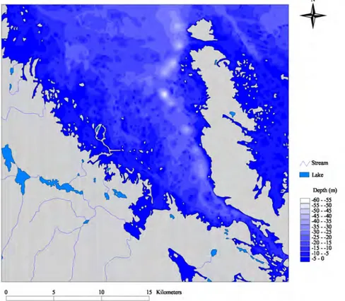
As shown in Figures 3.1 through 3.3 (from Brydsten, 1999), changes are ex-pected to include closure of the narrow strait that separates Grässö from the mainland, narrowing of Öregrundsgrepen, and eventual transition of the east-ern part of Öregrundsgrepen to a chain of freshwater lakes. These lakes are predicted to have high volumetric turnover, due to flow from the two region-al rivers that currently flow into Kregion-allrigafjärden (Forsmarksån and Oland-sån), continuing on via a new river that discharges to a distant Baltic.
Other lakes forming in shallow bathymetric basins in the western part of Öregrundsgrepen – including one just NW of the SFR – will be fed by only local streams and hence have lower turnover. The sea bottom directly above the current SFR facility predicted begin to emerge from the sea and to drain around 2400 AD, and to be “completely dry” (presumably sub-aerial) by 3500 AD (Brydsten, 1999).
Figure 3.1 Öregrundsgrepen with the water depth conditions that prevail as of 2000 AD. Figure from Brydsten
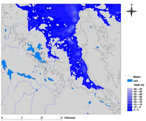
Figure 3.2 Öregrundsgrepen with the water depth conditions that are predicted to prevail in 4500 AD. The
current shoreline is marked (black lines) for reference. The larger rivers, their new extensions, and new larger lakes are also shown. Figure from Brydsten (1999).
Figure 3.3 Future lakes in Öregrundsgrepen after retreat of the Baltic from the area. SFR-1 is marked in red,
The Simpevarp investigation area consists of a small peninsula extending eastward into the Baltic, connecting to the mainland by a narrow strip of land plus two islands (Ävrö and Hålö) which are separated from the penin-sula by narrow straits. The Simpevarp area thus is nearly surrounded by wa-ter at sea level, limiting the likelihood of regional groundwawa-ter flow being a strong influence on the site. Thus present-day groundwater flow is expected to be driven mainly by the moderate local topographic relief on the peninsula and these two islands (nearly all below 10 m).
Laxemar is situated to the W and NW of Simpevarp, further inland on the same system of narrow straits between the peninsula and nearby islands. The general topographic gradient is (decreasing) toward the brackish strait between the east side of the Laxemar area and the island of Äspö.
The rate of land rise relative to sea level in the Laxemar-Simpevarp area is currently just 1 mm/yr (10 cm per 100 years). The brackish straits on the north side of the Simpevarp peninsula area, to the west of Ävrö, and around the island of Äspö, are generally less than 10 m deep so will fill in gradually over the next 10,000 years, leaving the current land areas as hills and hil-locks of high ground, bounded by wetlands and stream courses.
The Baltic deepens rapidly to the SE of Ävrö, reaching depths of over 10 m within about 250 m of the current shoreline. Hence only minor progression of the SE shoreline is expected during the interglacial period. The embay-ment to the south of Simpevarp is shallower so the shoreline will shift sea-ward in this area at a somewhat faster rate. However, in comparison with the Forsmark area, the position of the coastline relative to the Laxemar and Sim-pevarp areas is expected to be relatively stable for the remainder of the cur-rent interglacial period. The slower rate of shoreline progression at Oskar-shamn also means that the position of the interface between meteoric and brackish groundwaters has changed much less rapidly over recent centuries, compared to Forsmark.
Possible consequences of anthropogenic climate change
These expectations for shoreline progression in the Forsmark and Oskar-shamn areas are based on continuation of recent rates of land rise relative to sea level. However, as discussed by (SKB, 2006b) following the results of (IPCC, 2001, later updated in IPCC, 2007), anthropogenic greenhouse-gas emissions may result in short-term warming (over a time scale of centuries) and an extended interglacial warm period, resulting in short-term global sea level rises possibly as high as 7 to 14 m These rises in sea level should be offset by continuing isostatic rebound in the the Forsmark area, within the next two thousand years, and over a longer time period in the Laxemar area. The consequences of short-term climate change on sea level have been eval-uated for the operational phase of radioactive-waste repositories at Forsmark and Oskarshamn by Brydsten et al. (2009). For the year 2100 AD, extreme sea levels (including effects of transient storm surges along with
cli-mate-change effects) are expected to be 3.16 m or less at Forsmark, and 3.41 m or less at Laxemar-Simpevarp. The most extreme scenarios considered by
Brydsten (2009) would result in incursions of Baltic water up to 2 km inland of the present coastline at Forsmark, with near-submergence of the islands on which the SFR surface facilities are currently located, and also some parts of the planned surface facilities for the deep repository at Forsmark-lens. For the Simpevarp and Laxemar areas, incursion by Baltic waters would be much more limited due to the generally steeper shorelines.
Presumably (although not addressed by Brydsten et al., 2009), continued melting of Greenland and Antarctic glaciers beyond 2100 AD as predicted by the scenarios described by IPCC (2001; 2007) would lead to further in-creases in mean sea levels which would only be partly offset by continued isostatic land rise, leading to further inundation in the post-closure period. According to the persistent warm climate scenario developed by (SKB, 2006b), the higher global sea levels could continue for several thousand years.
Locally, this would mean that inundated areas at Forsmark would remain in that condition until the global sea level rise is offset by continuing isostatic land rise. The sequence of shoreline progression, narrowing of Öre-grundsgrepen, and transition to a chain of freshwater lakes, would presum-ably be delayed for some thousands of years into the future. During the peri-od of inundation, it seems likely that some of the recently formed lake-bed sediments and older glacial till in the Forsmark-lens area could be reworked by wave action, affecting local topography (although likely not bedrock-de-termined topography). Brackish waters could also re-infiltrate into sedi-ments and shallow bedrock in areas that had previously been infiltrated by lower-density meteoric waters. Thus in hydrologic terms, the consequences of global sea level rise due to anthropogenic warming would not be simply a “rewinding of the clock” to the state that existed several thousand years ago, but a more complex hydrogeochemical state with somewhat altered local to-pography and sediment distributions.
Local topography and Quaternary deposits/regolith
All of these sites, particularly the Forsmark area sites, have fairly low relief, due to a history of peneplanation and later continental glaciation. The rego-lith forms a discontinuous uppermost layer at all of the sites. Its properties can potentially potential affect the spatial and temporal variability of re-charge to the bedrock surface following precipitation events, as well as dis-charge from the bedrock.Forsmark area
The topography at Forsmark is gently undulating on the local scale with el-evations generally under 20 m.a.s.l. Bathymetry offshore in the Forsmark-S-FR are is also subdued, with sea depths generally less than 15 m, although basins as deep as 60 m occur in the regional area closer to Grässö.
The Forsmark-lens area is mostly overlain by Quaternary deposits, mainly glacial till, which covers 75% of the area, typically less than 5 m deep but up
to 15 m deep in places. Typically the deepest layers of till are found in bed-rock surface depressions. Over most of the area the till is sandy, but clayey till dominate in the SE part of the site. Forsmark also contains organic gyttja deposits, particularly in the bottoms of lakes and fens, which reduce the ver-tical permeability of near-surface sediments. About 5% of the area is ex-posed bedrock, i.e. lacking Quaternary deposits.
The Forsmark-SFR site lacks data on Quaternary deposits for some areas (cf. Figure 4-10 in Lindborg, 2010, SKB TR-10-05 and Figure 5-26 in Heden-ström and Sohlenius, 2008, SKB R-08-04). For the areas that have been characterised, till is the primary cover, followed by glacial clay (often topped with a thin layer of post-glacial sand or gravel). Areas of post-glacial fine sand are found to the N of the SFR. The offshore islets/skerries that rise above the sea typically have good bedrock exposure and little Quaternary cover, except where covered by artificial fill (e.g. for building site, cause-ways, and jetties in the SFR and biotest areas). The hydraulic conductivity of the glacial till has been estimated by Sigurdson (1987) to be within a range of 1x10⁻⁵ m/s through 1x10⁻⁸ m/s. (SKB R-01-02).
Laxemar-Simpevarp area
The Laxemar-Simpevarp area is entirely below 50 m.a.s.l., with distinct val-leys bordering elevated bedrock areas. Hummocky moraine is found in the SW and central part of the area, which results in locally undulating topo-graphy. A few eskers are found on the regional scale, one of which wends through the SW corner of the regional-scale model area.
The Quaternary deposits at Laxemar are dominated by sandy-gravelly till which overlies the bedrock in most of the area (Werner 2009; Grolander, 2009). Elevated areas are dominated by exposed bedrock or shallow till, while valleys have deeper deposits typically 5-10 m deep, consisting of post-glacial as well as post-glacial deposits. In most areas the till is overlain by post-glacial clay with low permeability, which affects groundwater discharge patterns in valleys, constraining discharge to areas where glacial and post-glacial depos-its are lacking (Grolander, 2009).
4. Bedrock characteristics
The main documents describing the bedrock geology of these sites are the site-descriptive models by Wahlgren et al. (2008) for Laxemar (with region-al-scale coverage of Simpevarp), and Stephens et al. (2007) for Forsmark-lens (with regional-scale coverage of the Forsmark-SFR site). Bedrock hy-drogeological site descriptions are presented by Rhén and Hartley (2008) for Laxemar, Follin (2008) for Forsmark-lens, and Axelsson et al. (2002) for SFR. An updated analysis of bedrock hydrogeology for Forsmark-SFR has recently been presented by Öhman & Follin (2010). This document, despite being published in SKB's P-report sequence, presents a significantly more advanced level of analysis than previous documents, and therefore is treated as a major reference for this report.
Bedrock origins, lithology and ductile deformation
The bedrock in the vicinity of all four sites is mainly granitic rock, formed in the Paleoproterozoic era. Rocks in the Forsmark area show strong foliation as a result of polyphase ductile deformation during the Fennian and Sveco-baltic orogenies at 1860-1800 Ma. Ductile shear zones formed during these events had a strong effect on later brittle deformation. Rocks in the Laxemar-Simpevarp area were less strongly affected by these events, and generally show only a weak foliation; however ductile shear zones developed which have since influenced brittle deformation.The Laxemar-Simpevarp area was also affected by igneous activity in the Mesoproterozoic era, around 1450 Ma. This produced the Götemar granite (around Lake Götemar to the north of the Laxemar model area), the Utham-mar granite a few km to the south of LaxeUtham-mar, and the granite island of Blå Jungfrun about 20 km SSE of Simpevarp.
Rocks of Mesoproterozoic or younger ages have not been found at Forsmark or in the immediate vicinity. Remnants of Jotnian sandstones are still found locally in the sea well to the NE of Forsmark, in the deepest depressions in the older bedrock surface (Tirén and Beckholmen, 2009).
The bedrock within the Forsmark-lens area is dominantly a medium-grained (meta)granite which has been affected by penetrative ductile deformation at mid-crustal depths and under high-temperature metamorphic conditions 1.87 to 1.86 Ga. Amphibolite and fine- to medium-grained granitoid were in-truded syntectonically as dykes and minor bodies. Locally, at least the am-phibolites gave rise to conspicuous alteration (albitization) in the older gran-itic rocks. Ductile deformation with folding continued to affect the younger intrusive rocks, including amphibolite, under lower metamorphic conditions, prior to 1.85 Ga. Subsequently, until at least 1.8 Ga, the ductile strain contin-ued to affect the bedrock, predominantly along the margins of the tectonic lens along discrete zones (Söderbäck 2008). Borehole data indicate that the
tectonic lens is a major geological structure that can be traced from the sur-face down to at least 1,000 m depth.
In the Forsmark-SFR area, the main rock type according to (Stephens et al., 2007) is a felsic to intermediate volcanic rock, metamorphic, and in part albitised. According to (SKB, 2008 /SKB R-08-67/) the rock volume within which the SFR is placed is strongly metamorphised and inhomogeneous, with fine-grained felsic rock types which have been evaluated as vulcanites and pegmatitic granite. Secondary rock types include metagranitoids, and dykes with amphibolite, pegmatite, and granite. Similar rocks are expected in the area to the SE which has been proposed for SFR expansion. However (SKB, 2008 /SKB R-08-67/) note that the mapping of seabed areas has been less intensive than on land, so some differences might be encountered. The predominant bedrock at in the Laxemar-Simpevarp area is a medium-grained, finely porphyritic rock that varies in composition between quartz monzodiorite, granodiorite, and granite. This rock is broadly referred to as Ävrö granite, despite the variable composition. A rock of more basic com-position, medium-grained quartz monzodiorite, is dominant in the southern part of the Laxemar local model area (Wahlgren et al., 2008). Important sub-ordinate rock types in the area include a fine-grained granite (or aplite), a fine-grained diorite-gabbro, and pegmatites. Dolerite dykes associated with later extensional tectonics around 900 Ma are also found, particularly in the western part of the Laxemar area.
Large-scale brittle deformation zones
Large-scale brittle deformation zones – including ductile deformation zones which have been reactivated in brittle deformation modes – are interpreted as being the most important water-conducting features in the bedrock for depths greater than 100-150 m, at all of these sites. Identification and charac-terisation of brittle deformation zones has therefore been a central focus of the geological investigations.
Structural configuration
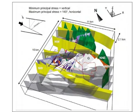
The Forsmark-lens site is situated in a shear lens between two NW- to WN-W-striking, anastamosing regional deformation zones, the Singö deformation zone on the NE side, and the Eckarfjärden deformation zone on the SW side. The target volume for the repository is in the footwall of a stack of gently SE-dipping fault zones. The target volume is bounded by the limbs and hinge of a steeply dipping synform, which helps to give confidence in down-ward projections of the lithology. The bounding regional-scale structures are also presumed to bound the extent of brittle deformation zones within the shear lens. The interpreted configuration of brittle deformation zones is illus-trated in Figure 4.1.
At Forsmark, the deformation zones which are interpreted as being most sig-nificant for site-scale flow (other than the regional shear zones that bound the shear lens that contains the candidate site) are a stack of gently dipping
brittle deformation zones that dip SE or SSE. These gently dipping zones show only brittle deformation. Most exhibit evidence of reverse dip slip and subordinate strike-slip displacements, implying origins in a compressive tec-tonic environment as thrust faults, but they also are interpreted as having been reactivated multiple times. Hydrologically these zones indicate strong, laterally extensive connections across the site. This has been confirmed by responses in observation wells during in pumping tests.
The local-scale hydrostructural model for Forsmark includes several dozen vertical or sub-vertical hydrogeological zones. These vertical/sub vertical hydrogeological zones at Forsmark result in an interconnected network of zones, particularly in the vertical direction, and provide routes of relatively high hydraulic conductivity (relative to the rock mass) via which groundwa-ter can be driven to depth (e.g. due to local topographic heads), lagroundwa-terally, and then upward.
At Forsmark, the vertical/sub-vertical zones tend to be relatively narrow fea-tures rather than broad zones, and in places may be represented by just a few discrete fractures.
The Forsmark-SFR site lies to the NE of the Singö zone, and thus is in a dif-ferent structural domain (though the surface facilities for the SFR are within the shear lens, and the access ramp passes through the Singö zone). One gently dipping zone (H2 in Figure 4.2) is similar in orientation to the stack of gently-dipping deformations zones in the Forsmark-lens.
A deformation zone regarded as a major splay of the Singö zone, ZFMN-W0805 in the nomenclature of (Stephens et al., 2007 /SKB R-07-45/), lies to the NE of the existing SFR tunnels. Thus the site lies within a wedge that is bounded on two sides by the Singö zone and a major splay of the Singö zone, opening toward the NW. Several additional deformation zones are in-terpreted as lying within this volume (Figure 4.2). The priority considered for SFR expansion is to the SE of the existing disposal tunnels, and thus moving toward the narrower part of this wedge.
Within the regional-scale geological site-descriptive model for the
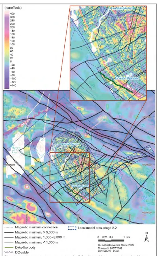
Forsmark-lens (Figure 4.1), which contains the Forsmark-SFR site, there is a noticeable deficit in the intensity of deformation zones in the portion of the model that is currently covered by the sea. This might be partly an artefact of the more limited data from the seabed areas. The structural wedge that con-tains the SFR site, in particular, has an anomalously low frequency of recog-nized deformation zones. However, the narrower part of this wedge to the SE of the SFR site is in a low-magnetic region (Figure 4.3), which is sug-gestive of more fractured rock, possibly including smaller-scale deformation zones that have not been recognized in the regional model for Forsmark.
Figure 4.1 3-D visualisation of the 131 deformation zones modelled deterministically for the Forsmark site
de-scriptive model, stage 2.2 (Stephens et al., 2007) focused on the Forsmark-lens site. The steeply dipping zones (107) are shaded in different colours and labelled with regard to their principal direction of strike. The gently dipping zones (24) are shaded in pale grey and denoted by a G. The border of the candidate area is shown in red and the regional and local model domains in black and purple, respectively (Fig 3-4 from Follin, 2008, SKB R-08-95).
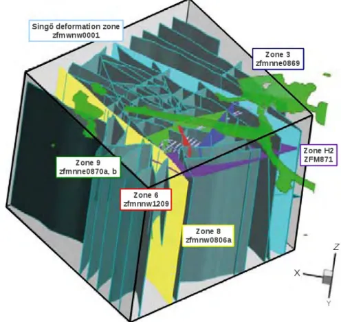
Figure 4.2 Interpreted configuration of brittle deformation zones at the Forsmark-SFR site, as viewed from the
NE looking toward the SW. The structural model extends to a depth of 490 m from level 0 according to the RHB70 elevation system, but here the vertical extent of the deformation zones is illustrated only for a level dir-ectly above the SFR (figure from Holmén and Stigsson, 2001).
An updated structural model for the Forsmark SFR site includes 58 “updated geological structures ... which require hydraulic parametrisation” according to Öhman & Follin (2010). These are shown as grey zones in Figure 4.4. This indicates a significantly higher intensity of structures within the wedge than was recognized in the Forsmark-lens site-descriptive model (although it should be noted that this structural wedge was outside the main area of focus for the site-descriptive model). At present, as noted by Öhman & Follin (2010), there is little or no information on the hydraulic properties of these structures. SKB (2008, R-08-67) note that, based on experiences from the Forsmark-lens site as described by Stephens et al. (2007), the representativ-ity of low-magnetic lineaments as indicators of deformation zones needs to be assessed, as some of these could represent rock types with low magnetic susceptibility due to oxidation of iron-rich minerals.
Figure 4.4 Deformation zones of the regional SFR domain (58) as defined in the preliminary structural model
SFR v. 0.1. The zones that existed in the previous structural model of Axelsson and Mærsk-Hanson (1997) are shown in colours similar to those for the same zones in Figure 4.2, with both the earlier and current names of the zones. Figure from Öhman & Follin (2010, P-09-49). The view is from the N/NE. According to Öhman & Follin (2010), updated structures are from SKBdoc 1224847 - DZ_SFR_REG_v0.1_prelim, Version 0.1, 2010-06-08.
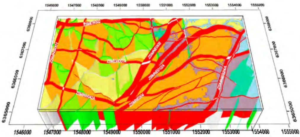
The Laxemar and Simpevarp areas have a differently oriented pattern of large-scale deformation zones (Figure 4.5), dominated by NE-striking, steeply to moderately dipping structures which are sub-parallel to the Äspö Shear Zone, and an intersecting set of E-W striking, southward dipping re-gional structures. On a large scale these structures have an anastamosing character, with NE-striking structures curving toward the east beyond the in-terference zone.
A set of N-S, steeply dipping regional structures occurring to the NW of the Äspö Shear Zone have been suggested by Wahlgren et al. (2008) to be pos-sibly related to the NE-striking structures, as Riedel shears in a strike-slip system dominated by the NE-striking structures. Several of these N-S struc-tures also have a radial configuration with respect to the younger granites (Götemar and Uthammar). The N-S set of structures are also associated with dolerite dykes which, when fractured internally or along their boundaries with the country rock, may be of hydrogeological significance.
The Simpevarp portion of the regional-scale structural model lies to the SE of the Äspö Shear Zone. In this area, N-S striking features longer than 1 km have not been found (the regional model contains one N-S deformation zone about 1 km long, which forms the strait between Ävrö/Jungfrun and the is-lands of Äspö and Hålö. Otherwise, the regional-scale fabric in the Sim-pevarp area is a series of elongated rock, apparent shear lenses bounded by the anastamosing NE- and E- striking deformation zones. This contrasts with the Laxemar area where deformation zones divide the area into an
as-semblage of more equidimensional blocks. Wahlgren et. al (2008) suggest that the Laxemar site can be viewed as part of a larger-scale “tectonic lens.” bounded to the NW and SE by systems of NE-striking, broad ductile belts represented by the deformation zones ZSMNE011A-90 to the NW, and ZSMNE004A and ZSMNE005A to the SE.
Figure 4.5 A 3-D view of large-scale deformation zones in the Laxemar regional model area (from SKB
Hydraulic properties of deformation zones
In the hydrogeological site-descriptive models, the term “hydraulic conduct-or domain” (HCD) is used to distinguish hydraulically conductive defconduct-orma- deforma-tion zones from the remainder of the bedrock, which is termed “hydraulic rock domain” (HRD). The correspondence of HCDs to geologically defined deformation zones is only approximate, as sometimes the significantly con-ductive part of a zone is just a small part of its geological thickness as ob-served in boreholes.
Forsmark-lens
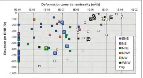
Hydraulic transmissivities measured in deformation zones at Forsmark are presented by Follin (2008, R-08-95). As seen in Figure 4.6, measured values range from less than the measurement threshold (10-10 m2/s or less) to a
max-imum of about 10-3 m2/s. At any given depth down to 900 m, the highest
measured transmissivities are associated with gently-dipping deformation zones. These gently-dipping zones show a trend of logarithmically decreas-ing transmissivity with depth.
For the more steeply dipping sets of deformation zones, the hydrogeological site-descriptive model for Forsmark (Follin et al., 2007b) uses a trend of de-creasing transmissivity with depth. While such a model can be fitted to the dataset, the evidence is ambiguous. For the steeply dipping sets of deforma-tion zones in Figure 4.6, no clear trend with depth is obvious, although a few very high values (>5x10⁻⁵ m2/s) are obtained for depths of less than 150 m in
WNW- and NW-striking deformation zones.
Among steeply dipping zones, the WNW-striking deformation zones are as-sociated with most of the transmissivity measurements above 10-6 m2/s,
al-though ENE-striking zones are responsible for two such measurements and a NW-striking zone accounts for another.
At shallow depths of under 100 m (i.e. depths at which an SFR extension would most likely be located), transmissivities of 10-5 m2/s or higher were
re-corded in all but one of the tested borehole-zone intersections, regardless of deformation-zone strike or dip.
Figure 4.6 Deformation-zone transmissivities vs. depth for deformation zones at Forsmark. Tests with no
measurable flow are assigned an arbitrary low transmissivity value of 10-10 m2/s in order to make them vis-ible on the log scale. Figure from Follin (2008, R-08-95, Figure 5-3). Larger “X” symbols denote measure-ments that were made in the last stage of site characterisation proper to SDM-Site.
Forsmark-SFR
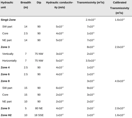
For the deformation zones around the SFR, early models developed by SKB made use of hydraulic conductivity values and zone thicknesses as given in Table 4.1. These are also presented here as transmissivities, for ease of com-parison. Two of the deformation zones (Singö Zone and Zone 8) were evalu-ated as being heterogeneous across their thickness, with a higher-trans-missivity “core” and lower-transhigher-trans-missivity outer parts. Another zone (Zone 3) was assessed as having anisotropic properties depending on whether flow was horizontal (along strike) or “vertical” (presumably along dip).
In later modelling, transmissivity estimates for the same zones have been ob-tained by calibration of a continuum model based on inflows to tunnels in the SFR (Holmén and Stigsson, 2001), and assuming homogeneous proper-ties within the zones. From Table 4.1, it may be noted that the calibrated val-ues are consistently lower than the initial estimates which were based on hy-draulic testing in boreholes that intersected these zones. If the values from the calibrated models are correct, this would imply either that (1) the earlier hydraulic tests were fortuitously located in relative high-transmissivity por-tions of the deformation zones, or (2) effective averaging of the deformation zone properties, as they act in the site-scale flow system, is more strongly in-fluenced by the low-transmissivity portions of these zones, than the aver-aging methods that were used for the early estimates. Alternatively, the transmissivity values estimated by calibration with respect to tunnel inflows might be too low, because the model neglected tunnel “skin” effects, which can occur due to a variety of causes including unsaturated-zone effects near the tunnel and hyperconvergence of channelized flow.
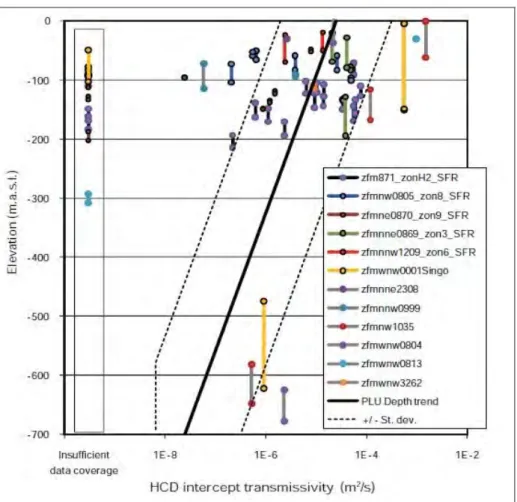
Most recently, Öhman and Follin (2009) have re-evaluated hydraulic data from the Forsmark-SFR area that were available prior to the initiation of the SFR extension programme. They present a new parametrization based on a trend in transmissivity with depth, assuming the same form of trend that was
applied for the Forsmark(-lens) site descriptive model by Follin et al. (2007b). The motivation for applying this parametrization at Forsmark SFR is, according to Öhman and Follin (2009), to give a reasonable extrapolation of the SFR dataset which comes mainly from depths of less than 150 m, to the greater depths of up to 1100 m that are considered in the new, v.0.1 mod-el of the Forsmark-SFR site.
Figure 4.7 shows the fitted trend in comparison with the reinterpreted trans-missivities from HCD intercepts with boreholes. The validity of a systematic trend with depth is arguable. However, this plot illustrates the substantial heterogeneity within these deformation zones, particularly the gently dipping Zone H2 for which point measurements of transmissivity within the depth range 100 m to 200 m vary across two orders of magnitude.
Further evidence of HCD variability is suggested by comparing transmissiv-ity estimates from single-hole hydraulic tests vs. interference tests, as sum-marized by Holmén and Stigsson (2001, SKB R-01-02, Tables 5.1 and 5.2). For a given zone, the interference-test estimates are systematically higher than the single-hole estimates, reflecting the likelihood that interference tests represent the most transmissive pathways between boreholes, rather than av-erage properties within the tested deformation zones.
Table 4.1 Estimated hydraulic properties of deformation zones in local model of SFR. Adapted from SKB
R-02-14, Table 3.3 (originally from SKB, 1993, Table 2-4). For the Singö Zone and Zone 8, net transmissivities are calculated as the sum of the transmissivities for different parts of the zones. For Zone 3, a geometric mean value of the anisotropic transmissivities is given. The transmissivity values in the last column are the based on values calibrated by Holmén and Stigsson (2001) and used by Odén (2009) in the SKB's v. 0.0 model for the SFR.
Hydraulic unit
Breadth (m)
Dip Hydraulic
conductiv-ity (m/s) Transmissivity (m2/s) Calibrated Transmissivity (m2/s) Singö Zone 2.4x10⁻⁵ 1.6x10⁻⁶ SW part 14 90 5x10⁻⁷ 7x10⁻⁶ Core 2.5 90 4x10⁻⁶ 1x10⁻⁵ NE part 14 90 5x10⁻⁷ 7x10⁻⁶ Zone 3 8x10⁻⁵ 2.0x10⁻⁵ Vertically 7 75 NW 3x10⁻⁶ 2x10⁻⁵ Horizontally 7 75 NW 5x10⁻⁵ 3.5x10⁻⁴ Zone 4 2.5 90 4x10⁻⁷ 1x10⁻⁶ Zone 6 2.5 90 4x10⁻⁷ 1x10⁻⁶ Zone 8 3x10⁻⁵ 4.0x10⁻⁶ SW part 15 90 6x10⁻⁸ 9x10⁻⁷ Core 15 90 2x10⁻⁶ 3x10⁻⁵ NE part 10 90 2x10⁻⁸ 2x10⁻⁷ Zone 9 5 80 NE 4x10⁻⁸ 2x10⁻⁷ 2.0x10⁻⁸ Zone H2 10 18 SSE 1x10⁻⁶ 1x10⁻⁵ 1.6x10⁻⁶
Figure 4.7 Transmissivities of deformation zones at Forsmark-SFR site, based on reinterpretation of older
borehole data. HCD transmissivity as function of depth, shown with a depth trend according to Follin et al. (2007). No HCD transmissivity is calculated for intercepts with insufficient data coverage (shown next to y-ax-is). Data points show modelled elevation interval of HCDs. Figure from Öhman and Follin (2009, P-09-49 Fig-ure 5-14).
Laxemar-Simpevarp area
Hydraulic properties of deformation zones within the Laxemar-Simpevarp regional area have been evaluated by Rhén et al. (2008). Measurements of transmissivity at borehole-zone intercepts have been analysed in terms of
four major categories of deformation zones:
Larger E-W striking zones;
Smaller E-W striking zones;
Larger zones of other orientations; Smaller zones of other orientations;
where the division between larger and smaller zones is based on whether the map traces extend for more or less than 2 km, respectively.
For each of these categories, trends in log transmissivity as a linearly de-creasing function of depth have been fitted to the data (Figure 4.8). Rhén et
al. (2008) note that heterogeneity is observed for deformation zones for
which transmissivities have been measured at multiple borehole intercepts. For individual zones, the standard deviation of log10(T) for individual zones
ranges from 0.5 to 2, but the highest standard deviations are associated with zones with a very small number of data points. The fitted trends have been applied in a depth-dependent model (Figure 4.9).
As for the Forsmark area, deformation zone transmissivities in the range 10-4
m2/s to 10-3 m2/s are encountered in the shallow bedrock, particularly for the
larger-scale zones (though for a few points in smaller zones). Values on the order of 10-5 m2/s are more typical for the smaller-scale deformation zones.
In addition to the deformation zones, dolerite dykes associated with the N-S deformation zones are found in the western part of the Laxemar area. Ac-cording to Rhén et al. (2008), the dolerite core of these dykes tends to be rel-atively impermeable, with hydraulic conductivity less than 10-9 m/s.
However, the flanking contacts with granitic rocks tend to be highly con-ductive, with transmissivities of 1.2x10⁻⁵ m2/s to 4.8x10⁻⁴ m2/s. Thus along
their strike and dip directions these dykes can act as significant conductors, but in the transverse direction, at least locally they may act as barriers to flow through the rock mass.
Figure 4.8. Deformation zone transmissivity (T) related to deformation zone strike direction and size, vs.
elev-ation Mean of log10(T) is plotted as well as the number of observations (n). Top figure shows data in regional model. Bottom figure shows regression line and data, regional model. Figure from SKB (2009, SKB TR-09-01, Figure 8-16).
Figure 4.9 Deformation zone (HCDs) in the Laxemar regional-scale model, with inferred depth-dependent
transmissivities. Oblique view from the south. The regional model volume used for groundwater flow simula-tions is shown in black; the area of this model is 21 km x 13 km with a bottom elevation at -2.3 km Figure from SKB (2009, SKB TR-09-01, Figure 8-25).
Bedrock excluding major deformation zones
The bedrock exclusive of major deformation zones is usually referred to as “rock mass” in SKB's documentation. The bedrock at all four of these sites is crystalline, and generally is effectively impermeable to groundwater flow in the absence of macroscopic fractures (the exception being one rock type, “vuggy granite” which is found in a few boreholes at Forsmark-lens, which has been altered by quartz dissolution to yield a skeletal rock of locally high permeability). Thus the hydraulic properties of the rock mass depend on the geometrical and hydraulic properties of the fracture system – specifically, on how these fractures connect to form networks on scales of meters to a kilo-metre or more.
The conceptual approach that has been used at the Laxemar, Simpevarp, and Forsmark-lens sites, and to a lesser extent at the Forsmark-SFR site, is the statistical discrete-fracture network (DFN) approach. The fundamental as-sumption of the statistical DFN approach is that, by building a statistical model that accounts for the geometry and hydraulic properties of individual fractures, networks of fractures can be constructed by stochastic simulation which reproduce, in a statistical sense, the hydraulic properties of the rock mass on the scales of interest. In particular, DFN models are often used to estimate effective continuum properties (i.e. effective hydraulic conductivity tensors, flow porosities, and flow-wetted surface, where these are valid for the scale of consideration).
A complete comparison of the statistical DFN models that have been de-veloped for these sites would require stochastic simulations, and is beyond the scope of this report. Instead, the fracture systems are compared in terms
of their general features. For the Forsmark-SFR site where models to date have been based mainly on continuum approximations, comparison is made in terms of the interpreted effective continuum properties.
At these sites, the principal information regarding permeability of typical bedrock (“rock mass”) comes from hydraulic injection tests on fixed inter-vals of drill holes, and (at the Laxemar, Simpevarp, and Forsmark-lens sites) differential flow-logging using the Posiva Flow Log (PFL) has been used. Larger-scale hydrologic testing using interference tests in multiple drill holes has focused on the more permeable deformation zones, which have been dis-cussed above. The single-hole methods essentially measure the local trans-missivity of fractures at their intersections with the drill holes. Injection tests sample all conductive fractures. The PFL samples only those that connect to larger-scale networks, and thus the PFL is more indicative of fractures that participate in large-scale flow.
Fracture system geometry and fracture hydraulic properties
For all three of the sites for which DFN models have been presented (Sim-pevarp, Laxemar, and Forsmark-lens), fracture sets have been deduced primarily on the basis of fracture orientation.
Simpevarp
For Simpevarp, two alternative DFN models are presented in the preliminary site descriptive model (SKB, 2005). Both of these models use the same definition for a single sub-horizontal fracture set, but combine these with dif-ferent assumptions regarding the sub vertical fracture sets (six sub vertical fracture sets, in each case). Alternative Model 1 includes three sets which are based on local lineaments, and three sets which are not, while in Alternative Model 2, all six sets are tied to the local lineament orientations. Both altern-atives have a relatively high proportion of NE-striking fractures vs. NW-striking fractures, which reflects the larger-scale structural geological fabric. The most extensive fractures, however, tend to be in the N-S direction. The Hydro-DFN models for Simpevarp did not distinguish among these sev-en differsev-ent fracture sets, in either alternative, whsev-en assigning hydraulic properties. Instead, three different sub-models for fracture transmissivity were tested for all seven fracture sets: a log-normal distribution of trans-missivity (uncorrelated to fracture length or size), a log-linear correlation between fracture length and transmissivity, and a semi-correlated model which includes a randomized “noise” term in the correlation.
Laxemar
At Laxemar, six different fracture domains were identified for different rock blocks and lithological units within the area (Figure 4.10). Four fracture sets (one sub-horizontal, and three sub vertical striking nominally N-S, ENE, and WNW) were identified by a combined analysis of fracture orientation data from all six domains. Then, for each of the four fracture sets in each of the
fracture domains, coupled size-intensity models were developed as presented by La Pointe et al. (2007).
Overall, the sub-horizontal fracture set was found to have the highest intens-ity (after correcting for borehole directional bias), followed by the N-S, ENE, and WNW sub vertical sets in that order. However, the relative intens-ities of these sets and coupled size-scaling models vary between fracture do-mains. For example, according to the intensity statistics presented by La Pointe et al. (2007, Table 7.1.2), the N-S set is relatively strong in the frac-ture domains FSM_NE005 and FSM_S which are in the SE part of the Lax-emar area, and also in FSM_W on the west side of the area. The WNW set is relatively strong in FSM_C in the central part of the site, and FSM_N in the northern part of the site.
Due to these variations in the intensity parameters, it should be expected that directional connectivities and anisotropy of effective hydraulic conductivit-ies could vary between fracture domains. However, because the DFN geo-metric models for Laxemar are expressed in terms of power-law scaling models in which fracture intensity statistics are coupled with size-distribu-tion scaling exponents and addisize-distribu-tional minimum and maximum radius para-meters, evaluation of the hydrogeological implications by inspection is not straightforward.
The hydrogeological implications of the geometrical DFN models were as-sessed after a further step in which statistical models for fracture trans-missivity (either correlated to, semi-correlated to, or uncorrelated to fracture size) for each fracture set were fitted by calibration of simulated flows to boreholes to obtain a statistical match to Posiva flow-log (PFL) anomaly data. The procedure is described by Rhén et al. (2008, R-08-78 Chapter 10). The models were developed for six Hydraulic Rock Domains (HRDs) which correspond to the fracture domains FSM_S, etc. but are denoted HRD_S, etc. in the hydrogeological model development. Within each HRD, models were calibrated for four different depth intervals (-1000 to -650 m.a.s.l., -650 to -400 m.a.s.l., -400 to -150 m.a.s.l., and -150 to 0 m.a.s.l.), resulting in 24 dif-ferent Hydro-DFN model variants (one per fracture domain and depth class).
Figure 4.10 Fracture domains at Laxemar. All northings and eastings are in the Swedish RT90(25 gon W) co-ordinate system. Figure from La Pointe et al. (2007, SKB R-08-55, Figure 4-6).
Forsmark-lens
At Forsmark(-lens), six different fracture domains were identified for differ-ent rock blocks and lithological units within the area (Figure 4.11). Geolo-gical (geometrical) DFN models were developed by Fox et al. (2007) for four of these fracture domains: FFM01, FFM02, FFM03, and FFM06. Fracture data from Forsmark show three broad groups of fractures by orient-ation, one of which is nominally horizontal while the other two are nomin-ally vertical, striking NE- and NW-striking, with the NE-striking set domin-ant. The Geo-DFN model for Forsmark (Fox et al., 2007, R-07-46) further divides these into as many as nine fracture sets, depending on the fracture domain. In contrast to Laxemar, fracture orientation distribution statistics for each set were derived independently by domain.
Coupled size-intensity models were developed following a methodology similar to that used for Laxemar. Three alternative models were presented in each case, to account for alternative assumptions regarding the relationship of large-scale fractures and fault zones inferred from lineament maps, to the smaller-scale fractures that could be observed on outcrops. The statistics of the fitted models are summarized in Fox et al. (2007, Section 7.3).
Figure 4.11 Fracture domain model for SDM Forsmark 2.2. Upper figure shows plan view of fracture
do-mains at sea level. Lower figure shows a three-dimensional visualisation of the fracture domain model. Frac-ture domains FFM01, FFM02, FFM03, and FFM06 are coloured grey, dark grey, blue, and green, respect-ively. The gently dipping and sub-horizontal zones ZFMA2 and ZFMF1 as well as the steeply dipping zones ZFMENE0060A and ZFMENE0062A are also shown. Figures from Fox et al. (2007, R-07-46, Figure 1-2) and from Olofsson et al. (2007, R-07-15, Figure 5-7).
Investigation of fracture location processes at Forsmark included both simple Poisson processes (uniformly random in three dimensions) and fractal mod-els which can produce more strongly clustered DFN simulations than are ex-pected with a simple Poisson process. A small but possibly significant de-gree of fractal clustering is indicated by the DFN analysis.
Another important aspect of fracture location is whether small-scale frac-tures are more likely to be found in rock bordering deformation zones.