MASTER THESIS
Model-checked
Space Plug-and-Play Architecture
Local Subnet Adaptation
implemented in Ada with
Ravenscar restrictions
Author
Christoffer Holmstedt
Supervisor Examiner
Adj. Prof. Fredrik Bruhn, PhD Prof. Kristina Lundqvist
M ¨ALARDALEN UNIVERSITY
School of Innovation, Design and Engineering
Abstract
Space Plug-and-Play Architecture (SPA) is a set of standards to make it eas-ier to build small satellites. Focus is put on improving the integration phase and the time consuming validation and verification process by introducing plug-and-play functionality. From mission call-up to operational satellite it should only take six days.
A SPA network consists of several different types of subnets with different pros and cons. For each processing node there must be one Local Subnet Manager (SM-L). The SM-L can communicate over different communication protocols depending on how the respective local subnet is set up, one option is UDP/IP.
In this thesis Ada Protected Objects is presented as a viable option for inter-process communication instead of UDP/IP in a SPA network. This thesis presents the initial work towards a SPA Local Subnet Adaptation that builds on language constructs in Ada such as Ada Tasks and Protected Objects. The system design and implementation is verified deadlock free with UPPAAL but shows indications of livelock possibilities. The severity of these livelock situations is discussed in the conclusion.
Keywords: Space plug-and-play Architecture, SPA, UPPAAL, Timed au-tomata, Ada, Ravenscar, Unified Common Architecture, UNICA, Virtual Network Protocol, VNP
Contents
List of Abbreviations iii
1 Introduction 1
1.1 Problem Statement . . . 2
1.2 Structure of this report . . . 3
2 State of the Art 4 2.1 Space plug-and-play Architecture . . . 4
2.2 UPPAAL . . . 6
2.3 Internet of Things . . . 7
3 Method 9 3.1 Literature study . . . 9
3.2 An Agile Unified Process . . . 10
4 Space Plug-and-Play Architecture 11 5 Designing and modeling the system 14 5.1 First iteration . . . 15 5.2 Second iteration . . . 18 5.3 Third iteration . . . 22 5.4 Verification . . . 23 6 Result 28 6.1 Model verification . . . 28 6.2 Implementation . . . 28 7 Conclusion 31 Bibliography 37 A System Design 38 A.1 Virtual Network Library implementation, high-level design . . 38
List of Abbreviations
AFRL Air Force Research Laboratory
AIAA American Institute of Aeronautics and Astronau-tics
BAP Bruhnspace Advanced Projects AB CAS SPA Central Addressing Service CDD Common Data Dictionary
CUUID Component Universally Unique Identifier IPC Inter-Process Communication
IP Internet Protocol LS SPA Lookup Service MDH M¨alardalen University SDM System Data Model
SM-L SPA Local Subnet Manager
SPA Space Plug-and-Play Architecture UDP User Datagram Protocol
UNICA Unified Common Architecture VNP Virtual Network Protocol XSD XML Schema Definition
Chapter 1
Introduction
Space plug-and-play Architecture (SPA) is intended to decrease the time needed in the integration phase when constructing satellites for specific mis-sions. This is done by introducing plug-and-play interfaces between different components, both software and hardware components. SPA is a set of stan-dards published by ”American Institute of Aeronatuics and Astronautics” (AIAA). The different standard documents define everything from power supply interfaces to how components automatically describe themselves to other components.
SPA has been developed since 2004 and has been shown to work as intended. As of early 2014 efforts are now taking place to broaden the scope of SPA under the names of ”Unified Common Architecture” (UNICA) and ”Virtual Network Protocol” (VNP). The goal with Unified Common Architecture is to introduce SPA concepts and ideas to the field of robotics, unmanned vehicles, industrial automation and internet of things. This work is done in a collaboration between M¨alardalen University (MDH) and Bruhnspace Advanced Projects AB (BAP) in Sweden.
VNP is a subset of the SPA standards that strictly limit the focus to the software parts of SPA. The goal is to try to stay interoperable with SPA as much as possible though some differences might be necessary to introduce. As a part of SPA is the ”inter-process communication” (IPC) through UD-P/IP within respective processing node. The dependability of UDUD-P/IP can be discussed but the starting point for this thesis work is that UDP/IP is not good enough, better options exist.
To increase dependability of a SPA network this thesis work will look at the possibilities of developing core parts of SPA in the Ada programming language which has a good track record in the field of safety-critical systems.
Focus will be on the local subnet which exists on each processing node. During implementation the system will be modeled with UPPAAL to verify specified requirements.
Before describing the problem statement it is important to define a few key terms. Both the term safety-critical system and high-integrity system are commonly used in different fields of research and communities. In this report the term critical system will be used and the definition of a safety-critical system is that it is dependable. ”Dependability” is a broad term and in this thesis the definition used by Aviˇzienis et al. [5] and Laprie [16] is used. More specifically the attributes in focus are availability, reliability, safety, integrity, maintainability and resilience in no specific order. Confidentiality is deemed out of scope and left for future work.
1.1
Problem Statement
This thesis work will focus on the core parts of a SPA network which runs on each processing node. This includes the Central Addressing Service (CAS), the Lookup Service (LS) and the Subnet Manager for ”Local Subnets” (SM-L) components. Only one instance of the CAS and LS runs within each SPA network at the same time but each processing node must have a SM-L running. Each component will be implemented as one or several Ada Tasks and communication between the Ada Tasks will be through Ada Protected Objects which is a shared memory construct defined as a part of the Ada programming language.
For SPA interoperability the SM-L will have two interfaces to other SPA components one to other local Ada Tasks through dedicated protected ob-jects and one through UDP/IP. The interface to external systems, the UD-P/IP interface, will be the system boundary of the analyzed system in this thesis.
The following list includes the questions to be answered
1. Does the system have any possibility to reach a state of deadlock? 2. Does the system have any possibility to reach a state of livelock? To answer these questions focus was first put on reading literature on how to develop safety-critical systems in Ada. Designing the system, implementing in Ada and modeling in UPPAAL was done over a few iterations to reach the end result.
1.2
Structure of this report
The report is structured as follows. Chapter 2 goes through the state of the art of Space plug-and-play Architecture, UPPAAL modeling and verification as well as Internet of Things. Chapter 3 continues with the research and development method used throughout the thesis work, from literature study to modeling and implementation. A thorough presentation on how Space plug-and-play Architecture works is then given in chapter 4. Chapter 5 presents how the system design and UPPAAL model have evolved over the development iterations. Chapter 6 shows all the results acquired and chapter 7 finishes the report with the discussion about the results and suggestions for future research and development.
Chapter 2
State of the Art
This chapter on the state of the art in related research fields aims at giv-ing the reader a basic steppgiv-ing stone for later chapters where more details are described concerning Space plug-and-play Architecture and UPPAAL modeling.
2.1
Space plug-and-play Architecture
The Air Force Research Laboratory (AFRL) Space Vehicle Directorate started a project referred to as ”Space plug-and-play Avionics” in 2004 with the in-tent to understand why space systems used in various missions became so complex and how they can be made easier to assemble [11, 26]. The solution was to look at plug-and-play systems already available on the ground. An example to this is how USB devices work with laptop and desktop comput-ers in everyday life. It does not matter which keyboard that is used, basic functionality will work in any computer it is used with, no matter if it runs Windows, OS X or a Linux distribution.
”Space plug-and-play Avionics” was released during the 2000-decade as a set of standards and in an updated version in 2011 renamed to ”Space plug-and-play Architecture” [26], all standards are available from AIAA [35]. Development and testing of implementations conforming to the standards have been ongoing since the launch of the program. One project that has been presented is the PnPSat by Fronterhouse et al. [11] and Martin et al. [25]. They have demonstrated the first created plug-and-play satellite and given their view on the problems encountered during development of both hardware and software components. The first plug-and-play satellite flown on orbit is presented by Martin et al. [26] where most parts of the
plug-and-play experiment passed all tests one year after launch.
As a critical part of plug-and-play satellite research and development is the ”System Data Model” (SDM) middleware software presented by Sundberg et al. [38], previously under the name ”Satellite Data Model” [23]. The SDM can be viewed in two different ways, as a middleware or as a ”sideware” [11]. The SDM is one implementation of the SPA standards that manage the parts of network and data capabilities discovery. The SDM source code has been released under public domain license [23].
As this thesis work focus on Ada the SDM source code available in C++ could not be used but it relates closely. This thesis is the starting ground for an Ada implementation that would be interoperable with the SDM. In other words, a SPA network could consist of multiple SDM processing nodes and multiple processing nodes running the Ada source code.
To enable components to be self-describing all SPA components must have an ”Extensible Transducer Electronic Data Sheet” (xTEDS) file stored within the component. The xTEDS file includes all the information other compo-nents need to understand its capabilities e.g. which interfaces the component has. The problem at this point is that multiple vendors start to create their own interface definitions and all benefits with self-describing components are lost. This is where the ”Common Data Dictionary” (CDD) comes into play.
The first work to create the CDD is described by Pasko as an informal approach. Instead Pasko suggests a more formal approach using Resource Description Framework (RDF). Pasko suggests that RDF and RDF Schemas can be used to not only describe the CDD formally but also be used to visually represent the CDD with suitable software [31].
Hansen et al. [12] describes the dictionary as an ontology which consists of several taxonomies in a hierarchical structure. This means that if different vendors create SPA components with temperature sensors, the vendors use the CDD to describe the interfaces with the correct vocabulary. To manage the risk of adding too many terms in the CDD Lanza et al. [15] suggests the forming of a CDD panel to ”[...] serve as a regulatory structure for the CDD”. To make it easier for developers to write xTEDS files with the correct vocabulary and improve the CDD, Lanza et al. [15] have created a web based tool to manage the CDD.
One benefit of using XML file structure for the xTEDS is that a XML schema definition (XSD) can be created and with the help of a XML validating parser xTEDS can be verified automatically to conform to the xTEDS file format and the CDD [15].
2.2
UPPAAL
To verify that a system meets safety-critical standards different approaches can be taken and depending on the severity of failures that can be caused by the system different approaches must be taken. To verify that the core SPA system implementation presented in this paper meets some basic re-quirements it will be modeled and verified with the model-checking tool UPPAAL.
On the official website UPPAAL is described as follows, ”UPPAAL is an integrated tool environment for modeling, validation and verification of real-time systems modeled as networks of real-timed automata, extended with data types (bounded integers, arrays, etc.).” [39]. It is maintained and developed by participants mainly from Uppsala University in Sweden and Aalborg University in Denmark.
The formal methods behind UPPAAL builds on the research originally pre-sented by Alur et al. [4] where real-time systems are shown to be modeled with timed finite automata, or just timed automata in short. The key part is that the system has a finite amount of states so it is possible to model it in a network of automata. Since the presentation of the formal method, tools have been developed to make the method useful. UPPAAL has over the last decade been forked to more specific versions such as ”TIMES” which can be used for schedulability analysis and ”TRON” for online real-time testing, other forks exist and for a more detailed history of the development process ”Developing UPPAAL over 15 years” by Behrmann et al. [7] is suggested. In this thesis ”classic” UPPAAL is used to verify real-time properties of the system.
UPPAAL is used mainly to verify real-time systems in a wide variety of research fields. From the field of radiation therapy [24] and safety-critical systems in the nuclear engineering domain [14] to embedded system in a university satellite [1] and flight-program in an unmanned helicopter [18]. Worth noting is that UPPAAL can also be used to verify protocols such as in a distributed lift system with a CAN Bus presented by Pang et el. [30] and the spacewire architecture presented by Ermont et al. [10].
The implementation presented in this thesis is done in Ada 2005 with the Ravenscar restriction to make it easier to verify requirements in a model-checking tool. Related to this is earlier work done in UPPAAL regarding Ada software and tasking. Bj¨ornfot presented ”Ada and timed automata” in 1996 [8] and Lundqvist et al. presented verification of an Ada RTS kernel with the Ravenscar restriction applied in four papers [22, 20, 19, 21].
2.3
Internet of Things
As part of this thesis work a first look at the field of Internet of Things is included and more specifically the different application layer protocols avail-able. This section lists the main other protocols and frameworks available for use in the field of ”Internet of Things” which could be related to the future of SPA and the ”Virtual Network Protocol” fork.
Constrained Application Protocol (CoAP)
Constrained Application Protocol (CoAP) is an application layer protocol going through standardization process in the IETF working group ”core”. The publication of the CoAP draft as a proposed standard is imminent as the document has reached ”Authors’ Final Review” as of May 2014 [13]. CoAP is designed for highly constrained nodes, that is nodes with a 8-bit microcontroller and very little ROM and RAM. Added to the hardware constrains the microcontrollers are often connected to lossy networks with low bandwidth. The protocol is a request-response protocol that relatively easily can be proxied to HTTP as it works with URIs in the same manner [9].
MQ Telemetry Transport (MQTT)
Originally invented in 1999 MQTT is a publish and subscribe, lightweight protocol designed for highly constrained nodes, just like CoAP. It runs over TCP/IP so it expects a network stack on all devices. A version of MQTT called MQTT-SN for ”Sensor Networks” is a branch of the protocol dedi-cated for networks without TCP/IP capabilities [28, 27]. The main protocol is undergoing standardization process in the OASIS organization, MQTT Working Group [29].
AllSeen Open Source project
From the beginning developed by Qualcomm as the AllJoyn project, the AllSeen Open Source Project is now run as a Linux Foundation Collaborative Project. It is a framework which offers service discovery, remote procedure calls, security and a lot of other features independent of the transport layer used. It is a framework with a core written in C++ with bindings to multiple other languages and runs on a wide variety of platforms from embedded to desktop devices [2, 3].
BACnet
In contrast to CoAP, MQTT and AllSeen Open Source Project the goal and primary concern for BACnet is building automation. BACnet, that is building automation and control networks, was originally started as stan-dardization project within the American Society of Heating, Refrigerating and Air-Conditioning Engineers (ASHRAE). After publication of the amer-ican standard it has since been published as both an european standard and an ISO standard [6].
Chapter 3
Method
This chapter describes the method used throughout the thesis work. First the literature study and then the method used for designing, modeling and implementation.
3.1
Literature study
To get a general understanding of the field and current state of the art, a literature study was conducted. The result of the study is presented in chapter 2. The literature study for Space plug-and-play Architecture and the Model Checking was conducted by selecting different key terms related to the topics and searching for them in two different search engines. The first one was Google scholar and the second one was the ”Discovery” search en-gine available to the students and employees of M¨alardalen University. The Discovery search engine search through multiple databases such as IEEE Xplore, ACM Digital Library and SpringerLink. For searches in the Discov-ery search engine only articles with full text available was requested. In Google scholar the first 20 results were looked into and the first 40 results given by Discovery search engine was looked into. Only results with full text PDFs were selected from Google Scholar.
A first read through of abstracts was conducted to filter out unrelated papers followed by a read through of introductions and conclusions for another filtering round. The key terms selected are shown below.
3.1.1 Space plug-and-play Architecture
The key terms chosen were ”Space and-play Avionics”, ”Space plug-and-play Architecture” and ”why Space plug-plug-and-play Avionics”.
3.1.2 Model Checking and UPPAAL
The key terms chosen were ”UPPAAL”, ”UPPAAL Modeling” and ”UP-PAAL Modeling Ravenscar”.
3.1.3 Internet of Things
”Internet of Things” is a broad field for research and development. As this is only a first look at the topic no specific key terms were selected instead previously known protocols were selected for a short presentation in section 2.3.
3.2
An Agile Unified Process
For the development process inspiration was taken from the Agile Unified Process presented by Larman in ”Applying UML and Patterns” [17]. As the SPA software is a framework no user stories nor use-cases was created instead the different SPA standards were used as a feature requirements list. Throughout the spring regular meetings took place to discuss design issues with the author of a related thesis work, Nils Brynedal Ignell. Major parts of the design and implementation have been created in collaboration. The implementation in Ada with ravenscar restriction in combination with the UPPAAL model of the system have been created in small increments to reach their final state.
Chapter 4
Space Plug-and-Play
Architecture
Space plug-and-play Architecture (SPA) is a set of standards that define how different players can create plug-and-play components that can easily be assembled to form a complete satellite for a specific mission. The stan-dards are published by American Institute of Aeronatuics and Astronautics (AIAA). The standards range from how power supply should be handled to how components communicate in the application layer, focus in this report is put on the software parts.
To describe how a SPA network works some terminology needs to be defined. All nodes in a SPA network are called ”components”, there is no differenti-ation between software and hardware components. Each component has a ”Component Universally Unique Identifier” (CUUID) which is 128 bit long. Each component also has an ”Extensible Transducer Electronic Data Sheet” (xTEDS) file that describes respective components capabilities. To be able to support different underlying link layer technologies such as Ethernet, Spacewire and one-wire, most functionality has been put in the application layer. This means that a SPA network can be built with any combina-tion of link layer ”subnets”, for example a SPA network can consist of two Spacewire subnets and one Ethernet subnet.
The important concepts to remember is that each SPA component is con-nected to one or more SPA subnets, on each SPA subnet there is a subnet manager (SM-x) that acts as a gateway to other SPA subnets and when SPA subnets are linked together they form a SPA network. To make things clear, a single SPA subnet with a CAS, LS and SM-x is also a SPA network. Spacewire and Ethernet have been mentioned earlier, another SPA subnet
is the SPA Local Subnet. Each processing node that can have multiple SPA components running on it has a ”SPA Local Subnet Manager” (SM-L). Components within a processing node should do inter-process communica-tion over UDP/IP [36].
Components communicate with each other with the help of ”logical ad-dresses” that each component receives during boot up. It is the responsib-lity of the ”Central Addressing Service” (CAS) to hand out logical addresses to all components in the SPA network through the connected Subnet Man-agers. After a component receives its logical address it can share its xTEDS file with other components. It is the responsibility of the ”Lookup Service” to keep track of the capabilities of each component in the SPA network. For a detailed overview of the discovery process see section A.2.
To describe what a SPA network can look like figure 4.1 shows a minimal SPA network which consists of a CAS, LS, a sensor and a monitor applica-tion, all running on the same processing node and in the same local subnet managed by the SM-L.
Figure 4.1: A processing node running a minimal SPA network.
A more complex SPA network is shown in figure 4.2. Three different pro-cessing nodes are connected to each other over a SPA-Ethernet subnet. The CAS, LS and Monitor Application are now running on different nodes and the sensor application is located on its own embedded device.
For a detailed view on how SPA works the SPA standards is the best source for information. The SPA standards and drafts that specify software re-quirements are the Logical Interface standard [32], Networking standard [33], Local Subnet Draft [36], Ontology Standard [34] and System Capabil-ities Standard [37].
Chapter 5
Designing and modeling the
system
This chapter includes the UPPAAL model in conjunction with correspond-ing UML diagrams describcorrespond-ing the implementation done in Ada. The UP-PAAL model is used for the validation and verification of the system that it meets the requirements set on the system. The connection from the UP-PAAL model to the UML diagrams presented here are to show that the implementation corresponds as close as possible to the models verified. The creation of the UPPAAL model presented in this chapter focus on the component and service discovery process. After the initial discovery and configuration process has been completed, the system continues in normal operation mode with an extra set of SPA message types that has not been modeled nor implemented. Detailed sequence diagrams over the component and service discovery process is shown in section A.2. The process from start to the final result is presented over a few iterations.
UPPAAL and SPA terminology
To better understand the following chapter a few words on the terminology used is necessary. A SPA component is either a SPA hardware de-vice or a SPA software application. In the design of the system a SPA application is implemented as an Ada task. In UPPAAL the same appli-cation is modeled as an automaton. The different SPA appliappli-cations such as CAS, LS and SM-L are modeled as different automata, together they form a network of automata which forms the UPPAAL model. A GUI is used to create the different automata but for more advanced features such as a queue or an object the underlying C-like language can be used instead.
The reason for this is that an automaton of a queue can easily become too complex to work with or verify.
The verification of the UPPAAL model is done by creating verification queries and sending them to the verification server that runs in the back-ground, all is done through the UPPAAL GUI.
5.1
First iteration
The first UPPAAL model was created after designing the basic structure of the system. Each application will do the same thing which is receive, handle and send messages. The difference between the applications is which messages each application understands and which messages the application will ignore. A processing node will at most have one CAS, one SM-L and one LS but can have any number of applications running next to them. This inspired the first iteration of the UPPAAL model. The application automaton should be possible to instantiate multiple times in UPPAAL but the other more specific automata can be used only ones. The basic SPA component overview is shown in figure 5.1 which is what the UPPAAL model is to resemble as close as possible.
Figure 5.1: A Processing Node overview with core SPA components.
A basic application
The basic functionality of an application is that it should be able to iden-tify itself on the network, share its capabilities and request information from
other applications. An application is only connected to one subnet at a time. The limited functionality of an application makes for a basic two-layered de-sign where the upper-layer alter its behaviour depending on incoming mes-sage types and the lower layer is only responsible for sending and receiving messages on its subnet. The application sends out Local Hello message dur-ing boot-up and receives a Local Ack response, all messages are modeled as transition between different states. It then receives a logical address with the Assign Address message. As final step it receives a Probe Request from the Lookup Service to share its capabilities. Figure 5.2 shows the UPPAAL model.
Figure 5.2: UPPAAL model of a first iteration application. Light blue text indicates synchronization channels, dark blue text indicates updates to variables and green text indicates guards in UPPAAL.
Central Addressing Service (CAS)
Specifics for the CAS is that it assigns an address to itself so there is no need for processing of Assign Address messages. As addition to basic application functionality the CAS sends out address blocks to the requesting subnet managers. Figure 5.3 shows the UPPAAL model.
Lookup Service (LS)
The additions the LS brings, is the processing of Request LS Probe, Probe Reply and Probe Request messages, for service discovery purposes. Figure 5.4 shows the UPPAAL model.
Figure 5.4: UPPAAL model of a first iteration LS.
Local Subnet Manager (SM-L)
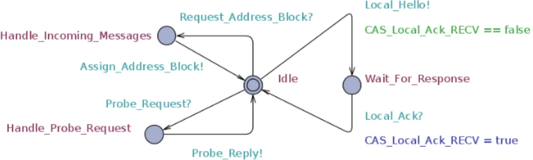
In contrast to the other components the Subnet Manager manages most of the interaction done in the subnet. It is responsible for answering all Local Hello messages during component discovery and replying with an ac-knowledgement as well as with an logical address assignment. As a last step it tells the LS to send out Probe Requests to all active components on the subnet. Figure 5.5 shows the UPPAAL model.
Conclusion from the first iteration
The CAS, LS and SM-L have specific functionalities so they can only be used once when setting up a complete network of automata. The application model can be instantiated multiple times as was the goal. At this level of abstraction everything looks fine, though the main goal with the UPPAAL model is to be able to verify that the system behaves as expected and can not reach erroneous states or deadlock. As the first iteration of models only shows the boot-up process it will eventually reach deadlock when everything is set up. This is a drawback as it does not relate very well with the actual design of the system after boot-up. This calls for another iteration and improvement of the different UPPAAL automata.
Before heading to the second iteration it is time to take a closer look at the UPPAAL automata and see what other parts need improvements, as it should resemble the actual system as much as possible.
First of is the current automata use transitions to model sent and received messages directly between the different automata. When a transition is taken to send a message the receiving automaton takes a corresponding transition to receive the message at the same time. This is in contrast with the implementation where all messages go through a queue. The second iteration of UPPAAL model should be modeled with proper queues that can be scaled in size.
The model only work with a set of eight different message types and in the current design of the UPPAAL automata it is hard to add more types of messages. The second iteration should make it possible to add and remove specific message types with ease.
5.2
Second iteration
To improve the UPPAAL model a more detailed design is required for the system. From the first iteration it is clear that the basic application can be designed in a generic fashion. The CAS and LS are more specific instan-tiations of the basic application and the SM-L has substantial differences. For easier maintenence of the models during the second iteration it would be valuable if the UPPAAL model could be created in a modular way. Two main automata would be the ”basic application” and the ”SM-L”.
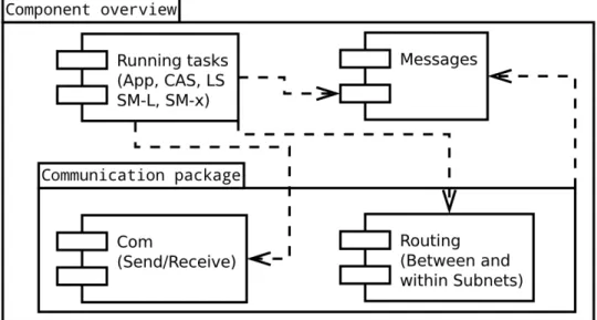
Figure 5.6 shows the UML component overview after the second iteration. The design of the interfaces between the components makes it easy to inter-change which message types each ”running task” (application) can handle
and how it communicates. A simple application that is only connected to one subnet does not need the routing component. The routing component is specifically created for the SM-L to be able to route traffic within its own subnet and to other subnets.
Figure 5.6: Component overview of a basic SPA implementation
The design of the communication package makes use of the ”composite pat-tern” where routing objects and com objects all inherit from the same in-terface and where the routing objects are of composite types. Figure 5.7 shows the difference between a simple application and the SM-L. The use of the composite pattern makes it possible for an application to easily swap out how it connects to one or multiple networks. In the implementation presented in this thesis this is done at compile time.
The queues
In the implementation of a local SPA subnet presented in this thesis, com-munication is done through protected objects in Ada. Each protected object includes two queues, one from the application to the SM-L and one back. To model this in UPPAAL the C-like language could be used to create the ac-tual queues in the background of the queue automaton. The finished queue is shown in figure 5.8. Each queue is instantiated for each SPA application including the CAS and the LS.
(a) An application (b) A Subnet Manager
Figure 5.7: The difference between a simple application and the SM-L.
A basic application
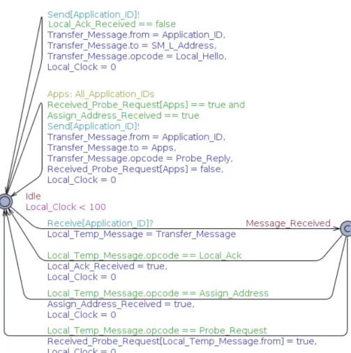
After modeling the queues the application was up next. The application automaton is shown in figure 5.9. In addition to the queues implemented in UPPAAL C-like language a ”Message” struct was also defined to model a SPA message, including its header. Each message is modelled with a source and a destination address as well as an opcode identifying what type of message it is.
A key assumption during iteration two was that upon receiving a message each application should send a response immediately. This was modeled in all automata including the one for the application. Upon receiving a message with the opcode Assign Address or Probe Request another message was sent in response before taking any other action. This introduced deadlock scenarios if the queue back to the SM-L was full the automaton for the application could not take any transition and if the queue to the application
Figure 5.8: Iteration 2 - The queue automaton
Figure 5.9: Iteration 2 - The application automaton
was full as well, both the SM-L and the application would be waiting for each other to empty their respective queue.
A solution to this that was tested allowed each application to throw away all incoming messages if no response could be sent back out. In turn each application had to keep track of which messages it had sent out and which responses it expected. After a few improvements this solution turned out to be too complex, resulting in a model that was hard to understand and time consuming to verify.
Second iteration conclusions
As too many problems arose with the second iteration only the application and queue automata are shown in the report. Even though the end result of iteration two was not good enough improvements were made throughout the iteration. The most significant improvements are presented in the list following this paragraph.
• Iteration two added the queue automaton which made it possible to model if and how the size of the queues would effect the system. • The addition of the Message struct made it possible to model different
types of messages being sent in the system.
• The logic throughout the system was vastly improved. • The possibility to vary the number of applications was kept.
5.3
Third iteration
The main focus of the third iteration was to remove the possibility of dead-locks. The underlying cause of deadlock was the tight coupling between receiving a message and sending a response. To loosen up the coupling dif-ferent approaches could be taken. One solution was to add time constraints such that if the outgoing queue was full the automata would wait for a set amount of time and then retry. It was early on apparent that this would not improve the deadlock situation.
A second solution and the one chosen was to make the assumption that when receiving a message the information is stored locally and then the application return to its idle state. From the idle state the application can then make a choice whether to receive another message or send a new message. The tight coupling was by this change completely removed.
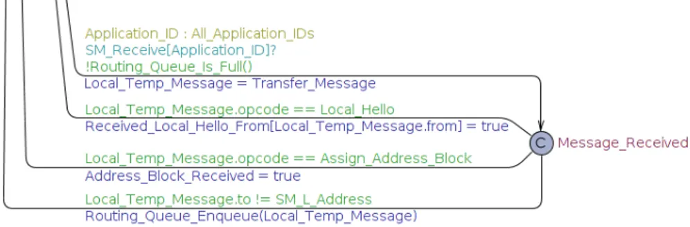
The automata from the third and final iteration are shown in figures 5.10, 5.11, 5.12, 5.13, 5.14 and 5.15. Together with the queue automaton (fig. 5.8) from iteration two they form the final model of a SPA Local Subnet that use Ada Protected Objects as communication channel.
Figure 5.10: Iteration 3 - The application automaton
5.4
Verification
To verify that the system is free of deadlocks and livelocks the UPPAAL verification queries presented in the end of this section were used. As the automata only test the component and service discovery process the goal is to reach a deadlock state in the end. To verify that it is only the final deadlock that can be reached the queries verify that all automata are in idle states and the appropriate variables have been set (all applications have been properly registered in the network).
The livelock query makes sure that all paths eventually reach the final dead-lock state. Both verification queries are shown below.
Figure 5.11: Iteration 3 - The receive loop part of the SM-L automaton
Verification query for deadlocks A [ ] d e a d l o c k imply
CAS . I d l e && SM L . I d l e && LS . I d l e &&
LS . R e c e i v e d P r o b e R e p l y [ CAS Address ] == t r u e && f o r a l l ( A p p l i c a t i o n I D : A p p l i c a t i o n I D T y p e ) A p p l i c a t i o n ( A p p l i c a t i o n I D ) . L o c a l A c k R e c e i v e d == t r u e && A p p l i c a t i o n ( A p p l i c a t i o n I D ) . A s s i g n A d d r e s s R e c e i v e d == t r u e && A p p l i c a t i o n ( A p p l i c a t i o n I D ) . I d l e && LS . R e c e i v e d P r o b e R e p l y [ A p p l i c a t i o n I D ] == t r u e
Verification query for livelocks
A<> CAS . I d l e && SM L . I d l e && LS . I d l e &&
LS . R e c e i v e d P r o b e R e p l y [ CAS Address ] == t r u e && f o r a l l ( A p p l i c a t i o n I D : A p p l i c a t i o n I D T y p e ) A p p l i c a t i o n ( A p p l i c a t i o n I D ) . L o c a l A c k R e c e i v e d == t r u e && A p p l i c a t i o n ( A p p l i c a t i o n I D ) . A s s i g n A d d r e s s R e c e i v e d == t r u e && A p p l i c a t i o n ( A p p l i c a t i o n I D ) . I d l e && LS . R e c e i v e d P r o b e R e p l y [ A p p l i c a t i o n I D ] == t r u e
Figure 5.12: Iteration 3 - The send loop part of the SM-L automaton
Figure 5.13: Iteration 3 - The routing loop part of the SM-L automaton. All messages with a destination that is not the SM-L are routed through this loop after first being received in the receive loop.
Chapter 6
Result
6.1
Model verification
The model presented in chapter 5 was verified with the verification queries presented in the same chapter.
• For deadlock verification the property was satisfied. • For livelock verification the property was not satisfied.
6.2
Implementation
The implemented SPA framework code called ”Virtual Network Library” is available on Github at https://github.com/virtualnetwork/vn-lib (in-cluding the third iteration and final UPPAAL model). The modular design is shown in figure A.1 and the source code compiles with the Ravenscar restrictions. Efforts have also been made to limit the amount of dynamic memory usage.
Example implementation is available in the ”examples” directory in the git repository. Below is a series of images that show example output from a test run. The example output is the same process as is described in section A.2 with UML sequence diagrams.
Figure 6.1: First the configured components start and send out Local Hello messages which are processed by the SM-L. SM-L replies with Local Ack to all other components and a specific Request Address Block to the CAS.
Figure 6.2: The CAS replies with Assign Address Block which is processed by the receiving SM-L. After this the SM-L starts to hand out logical ad-dresses to all components in the local interconnect. The logical adad-dresses are received by all applications. As a last step the SM-L sends out Re-quest LS Probe messages to the LS for all components on the local inter-connect. This last step is the end of the network discovery process and the start of the component data capabilities discovery process.
Figure 6.3: The LS receives the Request LS Probe messages and sends out Probe Request messages in response. The Application and CAS receives their respective Probe Requests and replies with a Probe Reply. The exam-ple output finishes with the LS receiving both Probe Reply messages.
Chapter 7
Conclusion
Presented in this thesis report is a model-checked implementation of a new subnet local adaptation of the Space plug-and-play Architecture. It has been implemented as the Virtual Network Library [40] for the fork of SPA called ”Virtual Network Protocol”. Instead of UDP/IP for IPC, Ada Protected Objects are used to share data between different Ada tasks.
When model-checking a system to verify that it behaves as expected it is important to get the model to resemble the implementation as close as pos-sible and vice versa. It is a network of two development artifacts that prove that the system behaves according to the specifications. In this thesis the specifications are the SPA standards and the implementation is the ”Virtual Network Library” implementation.
In chapter 5 the process that took place to reach the end result regarding the UPPAAL model and the implementation is shown. Going further with an even more detailed model would go into unnecessary detail such as how the routing tables or the CAS table are implemented. As the different tables are not going to hold any substantial amount of data, the time to do a lookup in the different tables are negligible. This among other things led to the conclusion that the level of abstraction of the model is at the right level for the purpose of this thesis.
The verification of the model shows that the only way to reach a deadlock is in the end state as expected, the problem comes with livelock. The verifica-tion query for livelock shows several different scenarios on how the system can reach a state of livelock. A very simple example is in the beginning when an application sends a Local Hello to the SM-L and the SM-L receives that message. When the SM-L is back in idle state the system reaches a livelock scenario because the application will keep sending Local Hello messages un-til it receives a Local Ack response. Similar scenarios arose throughout the
development of the model, for example when the SM-L sends a request to the CAS for an Address Block. Unless the CAS responds with an Address Block the SM-L would keep sending Address Block Requests forever. The solution to this scenario was to limit the SM-L to only send one message and make the assumption that all messages sent will be received. As communi-cation is through Ada Protected Objects this is an acceptable assumption to make in the current implementation.
The same solution could be used to the livelock problem with Local Hello messages. The drawback would be that if the application would be moved to any other type of subnet, the assumption about guaranteed delivery would not hold. In the end some kind of time based retry algorithm could be used, such as to resend the Local Hello message until a Local Ack is received with-out resending too often. To be able to model the different SPA applications in more detail they could be separated out and connected to an automaton representing the environment. This would allow testing of specific timings in different scenarios.
Future research - maintainability
One major consequence of moving away from UDP/IP as IPC is that the applications running on the different processing nodes no longer are modular in the sense that it is easy to add and remove applications on a processing node in a running system. When using Ada Protected Objects all SPA applications must be compiled together into one binary and started at the same time. This leads to future updates must replace the entire binary and reboot the system. The trade-off between Ada Protected Objects and a run-time modularity is something that need to be prioritized per project. For robots or satellites that are not connected to internet the increased reliability of protected objects may be a good trade-off. On the other side devices connected to internet that always must be up to date security wise to protect against intrusions, the modularity may be prioritized. An example to this could be a refrigerator that is connected to internet and a vulnerability is found in its transport layer security code. Instead of updating the entire running binary it would be enough just to update the specific module that exposes the vulnerability. Future work should take a deeper look at this trade-off, when is it worth the effort to use Ada protected objects over the modularity of UDP/IP for IPC?
Future research - security in general and confidentiality in partic-ular
For closed-circuit networks like remotely operated vehicles and some robots, security may not be that important but for the vast majority of devices secu-rity needs to be introduced. As soon as a device is connected to the Internet and starts to communicate with others it will need some kind of authenti-cation mechanism to allow access to its own data, it will need authorization mechanism to be able to differentiate between other devices regarding which device should get access to what data. Added to this is transport encryption (confidentiality) to prevent pervasive monitoring and the possibility of dis-closing private information to active listeners (man-in-the-middle attacks). How to add security to a SPA network with open access to internet is an important step forward to make SPA a viable option in the world of Internet of Things.
Future development - dependability of the development process
When starting this thesis Ada was chosen as programming language because of its track record with software that must be dependable to high-levels. Different ISO standards and white papers from AdaCore introduce good programming practices, how to develop good quality software and how to use object-oriented programming in the field of safety-critical applications. The approach all these papers use is that the developer and/or architect need to decide upon a few things first, before starting development.
First of the project must know what kind of safety level is expected from the system. This relates directly to how much testing, validation and ver-ification must be done throughout the development cycles and in the end when delivering the system. Testing, validation and verification techniques then influences the choice of programming features that can and more in-terestingly, should be used.
During the development and design phases in this project quite a lot of dis-cussions went into which level of safety that was expected. With a specific product in mind and its requirements this would have been less time con-suming. In the end, without specific safety requirements focus was put on which Ada features that were thought to be useful and which ones should be avoided. The reasoning behind this is that the fewer Ada constructs that were used the easier it would be to validate and verify in the future (and porting the system to new architectures). Future work should take a deeper look at the different safety standards that may be of interest and come up with firm programming guidelines that can be used during development.
Bibliography
[1] W. A. Alencar and E. Villani. Model Checking Applied to Embedded Software of University Satellite. Journal of Control, Automation and Electrical Systems, 25(1):126–136, 2013.
[2] AllJoyn Framework. https://www.alljoyn.org/about. Accessed 2014-05-12.
[3] AllSeen Alliance Open Source Project. https://allseenalliance. org/allseen/framework. Accessed 2014-05-12.
[4] R. Alur and D. L. Dill. A theory of timed automata. Theoretical computer science, 126(2):183–235, 1994.
[5] A. Aviˇzienis, J. Laprie, B. Randell, and C. Landwehr. Basic concepts and taxonomy of dependable and secure computing. IEEE Transactions on Dependable and Secure Computing, 1(1):11–33, 2004.
[6] BACnet official website. http://www.bacnet.org/index.html. Ac-cessed 2014-05-12.
[7] G. Behrmann, A. David, K. G. Larsen, P. Pettersson, and W. Yi. Developing UPPAAL over 15 years. Software-practice & Experience, 41(2):133 – 142, 2011.
[8] L. Bj¨ornfot. Ada and timed automata. In Ada in Europe, pages 389– 405. Springer, 1996.
[9] Constrained Application Protocol (CoAP). https://datatracker. ietf.org/doc/draft-ietf-core-coap/. Accessed 2014-05-12. [10] J. Ermont and C. Fraboul. Modeling a spacewire architecture using
timed automata to compute worst-case end-to-end delays. In Emerging Technologies & Factory Automation (ETFA), 2013 IEEE 18th Confer-ence on, pages 1–4. IEEE, 2013.
(PnPSat). AIAA Infotech@ Aerospace, 2007.
[12] L. J. Hansen, D. Lanza, and S. Pasko. Developing an ontology for stan-dardizing space systems data exchange. 2012 IEEE Aerospace Confer-ence, page 1, 2012.
[13] IETF Working Group Constrained RESTful Environments (core). http://datatracker.ietf.org/wg/core/. Accessed 2014-05-12. [14] J. Lahtinen, J. Valkonen, K. Bj¨orkman, J. Frits, I. Niemel¨a, and K.
Hel-janko. Model checking of safety-critical software in the nuclear engi-neering domain. Reliability Engiengi-neering & System Safety, 105:104–113, 2012.
[15] D. L. Lanza, R. W. Vick, and J. C. Lyke. The Space Plug-and-play Avionics Common Data Dictionary - Constructing the language of SPA. In AIAA Infotech at Aerospace 2010, Science Applications International Corporation, Applied Sciences Operation, 2010.
[16] J. Laprie. From dependability to resilience. In Proceedings of the 38th Annual IEEE/IFIP International Conference on Dependable Systems and Networks, 2008.
[17] C. Larman. Applying UML and patterns : an introduction to object-oriented analysis and design and iterative development. Upper Saddle River, N.J. : Prentice Hall PTR, c2005., 2005.
[18] D. Lee, S. Sung, J. Yoo, and D. Kim. Formal modeling and verifica-tion of operaverifica-tional flight program in a small-scale unmanned helicopter. Journal of Aerospace Engineering, 25(4):530–540, 2011.
[19] K. Lundqvist and L. Asplund. A formal model of a run-time kernel for ravenscar. In Real-Time Computing Systems and Applications, 1999. RTCSA’99. Sixth International Conference on, pages 504–507. IEEE, 1999.
[20] K. Lundqvist and L. Asplund. A formal model of the ada ravenscar tasking profile; delay until. ACM SIGAda Ada Letters, 19(3):15–21, 1999.
[21] K. Lundqvist and L. Asplund. A ravenscar-compliant run-time kernel for safety-critical systems. Real-Time Systems, 24(1):29–54, 2003. [22] K. Lundqvist, L. Asplund, and S. Michell. A formal model of the
ada ravenscar tasking profile; protected objects. In Reliable Software TechnologiesAda-Europe99, pages 12–25. Springer Berlin Heidelberg, 1999.
[23] J. C. Lyke and J. Calixte-Rosengren. System Data Model (SDM) source code, USAF technical paper ADA570990. http://www.dtic. mil/docs/citations/ADA570990. 2014-02-18.
[24] K. L. Man, T. Krilavicius, K. Wan, D. Hughes, and K. Lee. Modeling and analysis of radiation therapy system with respiratory compensation using uppaal. In Parallel and Distributed Processing with Applications Workshops (ISPAW), 2011 Ninth IEEE International Symposium on, pages 50–54. IEEE, 2011.
[25] M. Martin, D. Fronterhouse, and J. Lyke. The implementation of a plug-and-play satellite bus. 2008.
[26] M. Martin, J. Summers, and J. Lyke. AFRL plug-and-play spacecraft avionics experiment (SAE). 2012 IEEE Aerospace Conference, page 1, 2012.
[27] MQTT Documentation. http://mqtt.org/documentation. Accessed 2014-05-12.
[28] MQTT Official Website. http://mqtt.org/. Accessed 2014-05-12. [29] OASIS MQTT Working Group. https://www.oasis-open.org/
committees/mqtt/. Accessed 2014-05-12.
[30] J. Pang, B. Karstens, and W. Fokkink. Analyzing the redesign of a distributed lift system in UPPAAL. In Lecture notes in computer sci-ences, International conference on formal engineering methods, pages 504 – 522, 2003.
[31] S. S. Pasko. Using RDF schema and taxonomies to describe a flexi-ble, standards based spa ontology. In Infotech@ Aerospace Conference, Unleashing Unmanned Systems, AIAA. AIAA, 2011.
[32] Space Plug-and-Play Architecture: Logical Interface (AIAA S-133-3-2013e). http://arc.aiaa.org/doi/book/10.2514/4.102318. Ac-cessed 2014-02-17.
[33] Space Plug-and-Play Architecture: Networking (AIAA S-133-2-2013e). http://arc.aiaa.org/doi/book/10.2514/4.102301. Accessed 2014-02-17.
[34] Space Plug-and-Play Architecture: Ontology (AIAA S-133-7-2013e). http://arc.aiaa.org/doi/book/10.2514/4.102356. Accessed 2014-02-17.
[35] Space Plug-and-Play Architecture: Package Set. http://arc.aiaa. org/doi/book/10.2514/4.102431. Accessed 2014-02-17.
[36] Space Plug-and-Play Architecture Standard DRAFT: Local Subnet Adaptation.
[37] Space Plug-and-Play Architecture: System Capability (AIAA G-133-10-2013e). http://arc.aiaa.org/doi/book/10.2514/4.102387. Ac-cessed 2014-02-17.
[38] K. Sundberg, S. Cannon, T. Hospodarsky, and D. Fronterhouse. The satellite data model. In ESA, pages 10–15, 2006.
[39] UPPAAL Website. http://uppaal.org/. Accessed 2014-05-07. [40] Virtual network protocol library implementation. https://github.
Appendix A
System Design
This appendix shows the overall design of the system in UML layer, class and sequence diagrams.
A.1
Virtual Network Library implementation,
high-level design
To get one simple application up and running in a ”Virtual Network” the application’s settings need to be defined in the Application Information com-ponent. This ranges from everything from CUUID to other custom settings that may be needed. The Application Information component also keeps track of the application’s logical address during run-time and supplies dif-ferent helper functions, one of which is to fill in VN.Message header infor-mation.
The next step is to add connectivity. If the application only runs on a processing node or on a single subnet all that is needed is a
VN.Communication.Com implementation of that specific subnet type. The more advanced use case is a subnet manager that manages its own subnet and is connected to a Local Subnet Manager on the processing node it runs on. As this requires connectivity on more than one subnet a Protocol Routing object will be needed to route traffic between subnets. The Protocol Routing object is a composite type of the VN.Communication.Com interface and can therefore add multiple subnets during startup procedures.
All communication on a processing node through Ada Protected Objects goes through the Subnet Manager as a router. This leads to all applications on a processing node only has to instantiate one connection. This is done
Figure A.1: Component overview of the Virtual Network Library implemen-tation.
by first instantiating one Protected Object (PO) through the
VN.Communication.PO component. An access to this PO can then be used as input parameter when creating the two VN.Communication.PO Wrapper’s, one for the application and one for the local subnet manager.
The application itself is written as an Ada task and due to Ravenscar limiti-ation must be built from the ground up for each new task. Best way to start is to copy an example task from the ”examples” directory in the repository [40].
A.2
Component and Service discovery process
The following sequence diagrams show the basic component and service discovery process for a local subnet using UDP/IP for inter-process commu-nication described in SPA Local Subnet Adaptation Draft [36] (the sequence of messages sent back and forth is the same for a Local Subnet with Ada protected objects).
Figure A.2 starts with the high-level view of a complete SPA network. Figure A.3 continues with the specifics of a SPA Local Subnet. Figure A.4 shows the specifics on how a SPA Subnet Manager acquires an address block from the CAS and after that the SPA Subnet Manager assigns a logical address to each component it is aware of in figure A.5. The last step is the component capabilities discovery process where the LS collects information about all known components on the network, this is shown in figure A.6.
Figure A.4: How the local subnet manager acquires address blocks from the CAS for its own subnet and for other connected subnet managers.
Figure A.5: After the SM-L has received Address Block it starts to assign logical addresses to local components it is aware of.
Figure A.6: The last step in the discovery process is to discover which components have which services.