Further Development of a Rescue Helmet
ARTUR ADSON
TIMU MATIN
Master of Science Thesis Stockholm, Sweden 2014
Further Development of A Rescue Helmet
Artur Adson
Timu Matin
Master of Science Thesis MMK 2014:100 IDE135 KTH Industrial Engineering and Management
Technical Design SE-100 44 STOCKHOLM
Master of Science Thesis MMK 2014:100 IDE135
Further Development of A Rescue Helmet
Artur Adson Timu Matin
Approved
2015-01-30
Examiner
Carl Michael Johannesson
Supervisor
Carl Michael Johannesson
Commissioner
AUK Protection
Contact person
Björn Berggren
Abstract
The aim of this master's thesis was to further develop a helmet for search and rescue personnel, on request from AUK Protection, formerly known as Baering. This thesis succeeds the KTH MF2061 higher course project Baering Y1 - Product development of a new search and rescue helmet in collaboration with Baering in 2013.
AUK Protection had identified a need for a purposely designed helmet through contact with members of Swedish Search and Rescue(SAR) and Swedish Sea Rescue Society(SSRS). There are approximately 2000 active SAR and SSRS members who use helmets designed for recreational activities, such as rafting and mountain climbing, for lack of a better alternative. The helmets are consequently modified to accommodate their specific needs. Essential rescue equipment, such as position lights and communication systems, are retrofit using fasteners, tape, straps and Velcro. User studies conducted in the MF2061 project indicated safety concerns with the aforementioned attachment methods. The retrofit components protrude from the helmet and often interfere with other rescue equipment, with the risk of entangling the user.
The Y1 helmet concept produced in the MF2061 project was evaluated together members from SAR and SSRS, with focus on form and functionality. Different materials and manufacturing methods were researched and the manufacturability of the Y1 was analysed. It was ultimately decided to discontinue the development of the Y1 due to the feedback received. New concepts were generated with focus on anthropometric data, manufacturability, helmet safety standards and the ability to mount additional components. Different material combinations were investigated and evaluated using physical testing. Further development of the concepts involved clay sculpting and 3D CAD modelling. The final concept was chosen based on input from the users, AUK Protection and HOWL Design Studio.
The R1 -Rescue One helmet is the result and supersedes currently available solutions for rescue applications. The essence of the R1 helmet is a modular mounting system that can be customized for use with third-party components. Prototypes were manufactured in the correct materials for further evaluation. Drop tests were performed according to PAS 028 standard validate the mechanical properties of the helmet.
Sammanfattning
Syftet med denna magisteruppsats var att vidareutveckla en hjälm för livräddningspersonal, som gjordes på begäran från AUK Protection, tidigare känd som Baering. Denna avhandling efterföljer MF2061 högre kurs-projektet Baering Y1 - Product development of a new search and rescue helmet in collaboration with Baering som genomfördes i KTH år 2013.
AUK Protection hade identifierat ett behov av en speciellt utformad hjälm genom kontakt med medlemmar i svenska Search and Rescue(SAR) samt Sjöräddningssällskapet(SSRS). Det finns omkring 2000 aktiva SAR och SSRS medlemmar som använder hjälmar avsedda för fritidsaktiviteter, såsom forsränning och bergsklättring, i brist på ett bättre alternativ. Hjälmarna modifieras följaktligen för att tillgodose deras specifika behov. Nödvändig räddningsutrustning, exempelvis positionsljus och kommunikationssystem, monteras på hjälmen med hjälp av skruvar, tejp och kardborreband. Användarstudier i MF2061-projektet indikerade att dessa monteringsmetoder medför säkerhetsrisker. Enligt SAR Norrtälje hakar utstickande komponenter som är monterade på hjälmen ofta fast i övrig räddningsutrustning, med risk för att trassla in användaren.
Y1 hjälmkonceptet, som produceras i MF2061-projektet, utvärderades med avseende på form och funktion tillsammans medlemmar från SAR och SSRS. Olika material och tillverkningsmetoder undersöktes och producerbarheten av Y1 analyserades. Det beslutades slutligen att avbryta vidareutvecklingen av Y1 baserat på feedbacken som erhölls. Nya koncept genererades med fokus på antropometrisk data, producerbarhet, säkerhetsstandarder för hjälmar och förmågan att montera ytterligare komponenter. Olika materialkombinationer undersöktes och jämfördes med hjälp av fysiska tester. Vidareutvecklingen av koncept involverade skulptering i lera och 3D CAD modellering. Det slutliga konceptet valdes utifrån input från användarna, AUK Protection och HOWL Design Studio.
Resultatet, hjälmen R1 - Rescue One, ersätter tillgängliga lösningar för räddningsapplikationer. Det som utmärker R1-hjälmen är ett modulärt monteringssystem som kan anpassas för användning av tredjepartskomponenter. Prototyper av R1 tillverkades i korrekta material för vidare utvärdering. Falltester utfördes i enlighet med PAS 028 standarden för att validera de mekaniska egenskaperna hos hjälmen.
Examensarbete MMK 2014:100 IDE135
Further Development of A Rescue Helmet
Artur Adson Timu Matin
Godkänt
2015-01-30
Examinator
Carl Michael Johannesson
Handledare
Carl Michael Johannesson
Uppdragsgivare
AUK Protection
Kontaktperson
FOREWORD
These are the people we would like to thank for making this project possible.We would like to give our sincere thanks to Björn Berggren, Michael Elmeskog, Linus Wikander and Johan Bauman at Baering, and our supervisor Carl Michael Johannesson, for giving us the opportunity to work on this rewarding thesis project.
We want to thank Thore Hagman, Mats Ryde, Jens Samuelsson and Fredrik Falkman at SSRS, and Per-Magnus Grönlund and Marcus Johansson at SAR, for their user insights and time.
The design feedback we received from HOWL design studio was very valuable and for that we thank Oscar Karlsson.
Edvin Eminovic, student and research assistant at KTH, has our appreciation for supporting us in prototype manufacturing.
We also want to thank Peter Halldin, Kim Lindblom at MIPS for their feedback and assisting us with drop testing of helmets.
Lastly, we want to thank our contacts at various suppliers and manufacturers for advice on materials and manufacturing, in no particular order: Ola Listerud from Formplast, Peter Ljungberg from Wetaplast, Jesn Grunwald from Arpro, Michael Gryvik from Arla Plast and Anders Gustafsson from AQ Plast.
Artur Adson & Timu Matin Stockholm, November 2014
6
NOMENCLATURE
The notations, abbreviations and software used in this master's thesis are listed and described here.
Notations
Symbol
Description
E Young´s modulus (Pa)
𝐸𝑃 Potential energy 𝐸𝐾 Kinetic energy r Radius(m) t Thickness (m) ℎ Height (m) 𝑚 Mass (kg) 𝑔 Gravitational constant, 9,81 (m/s2)
𝑝𝑠𝑖 Pound force per square inch (lbf/in2)
Abbreviations
CAD Computer Aided Design
CAE Computer Aided Engineering
CAM Computer Aided Manufacturing
CNC Computer Numerical Control
PLM Product Lifecycle Management
DFM Design For Manufacturing
SAR Search and Rescue (Swedish)
SSRS Swedish Sea Rescue Society / Sjöräddningssällskapet ABS Acrylate butadiene styrene
PC Polycarbonate
LD Foam Low Density polyurethane foam
EPP Expanded Polypropylene
Software used
Adobe Illustrator CS6 Adobe Photoshop CS6 Microsoft Word 2010 Microsoft Excel 2010 CES EduPack SolidWorks 2013Autodesk Inventor Professional 2015 Autodesk Simulation Moldflow Keyshot 5
8
Table of contents
1 INTRODUCTION ... 1 1.1 BACKGROUND ... 1 1.2 PURPOSE ... 2 1.2.1 Deliverables: ... 2 1.2.2 Delimitations ... 2 2 METHODS ... 32.1 ITERATIVE DESIGN PROCESS ... 3
2.2 PROJECT PLANNING METHODS ... 3
2.2.1 Project plan ... 3
2.2.2 GANTT-chart ... 3
2.3 INFORMATION RETRIEVAL ... 3
2.4 COMPETITOR ANALYSIS ... 4
2.5 MATERIAL ANALYSIS ... 4
2.6 SEMI-STRUCTURED INTERVIEWS ... 4
2.7 IDEATION WORKSHOP ... 4 2.8 FOCUS GROUP ... 4 2.9 IDEATION ... 4 2.9.1 Brainstorming ... 4 2.9.2 Moodboard ... 5 2.9.3 Speed sketching ... 5 2.9.4 Exploratory sketching ... 5 2.10 EVALUATION ... 5 2.10.1 Pugh-matrix ... 5 2.10.2 SWOT-analysis ... 6 2.10.3 Clay model ... 6 2.10.4 CAD ... 6 2.10.5 Physical prototype ... 6 3 FRAME OF REFERENCE ... 7 3.1 PROJECT PLAN ... 7 3.2 USER GROUPS ... 7 3.2.1 SAR ... 7 3.2.2 SSRS ... 8 3.3 ERGONOMICS ... 9 3.3.1 Head sizes ... 9 3.3.2 MIPS ... 11
3.4 ESSENTIAL HELMET COMPONENTS ... 11
3.4.1 Outer shell ... 11 3.4.2 Inner liner ... 12 3.4.3 Comfort liner ... 12 3.4.4 Chinstrap ... 12 3.4.5 Retention system ... 12 3.5 EXTERNAL COMPONENTS ... 12 3.5.1 Communication ... 13 3.5.2 Eye protection ... 13 3.5.3 Camera ... 13 3.5.4 Snorkel ... 13 3.6 STANDARDS ... 14 3.6.1 Helmet standards ... 14 3.6.1.1 PAS 028 ... 14
3.6.1.2 Testing according to PAS 028 ... 15
3.6.2 Component standards ... 16
3.7.1 Main competitors ... 17
3.7.1.1 Predator... 17
3.7.1.2 Gecko ... 18
3.7.1.3 Manta Hi-Viz SAR Multi-Role Helmet ... 18
3.7.1.4 OPS-core FAST ... 19 3.8 MATERIALS ... 20 3.8.1 Outer shell ... 20 3.8.1.1 Composite shell ... 20 3.8.1.2 ABS ... 21 3.8.1.3 PC ... 21 3.8.2 Inner liner ... 21 3.8.2.1 EPS ... 21 3.8.2.2 EPP ... 21 3.8.2.3 EVA ... 22
3.8.3 Inner liner and shell combination ... 22
3.9 MANUFACTURING ... 23 3.9.1 Injection moulding ... 23 3.9.2 Thermoforming ... 24 3.9.2.1 Vacuum forming ... 24 3.9.2.2 Pressure forming ... 25 3.9.2.3 Design recommendations ... 25
3.9.3 Expanded foam moulding ... 26
3.10 ASSEMBLY METHODS ... 27
3.10.1 Spray Adhesive ... 27
3.10.1.1 Double-sided adhesive ... 27
3.10.1.2 Two component glue ... 27
3.10.2 Fasteners ... 27 3.10.3 External components ... 27 3.10.3.1 ACH-ARC rail ... 28 3.10.3.2 Picatinny Mount ... 29 3.10.3.3 Commercial mounts ... 30 4 IMPLEMENTATION ... 32 4.1 EVALUATION OF Y1 ... 32
4.1.1 Workshop with SAR ... 32
4.1.2 Workshop with SSRS ... 32
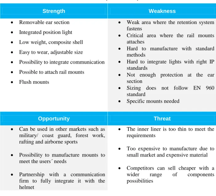
4.1.3 SWOT-analysis of Y1 ... 35
4.2 DESIGN REQUIREMENTS ... 35
4.2.1 Interview with Mikael Swarén ... 36
4.2.2 Inner liner thickness ... 37
4.3 MATERIAL ANALYSIS ... 37
4.3.1 Material requirements ... 37
4.3.2 Benchmarking ... 38
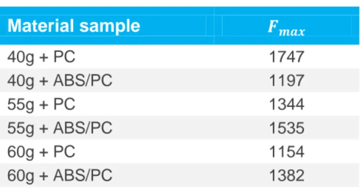
4.3.3 Material sample droptest ... 38
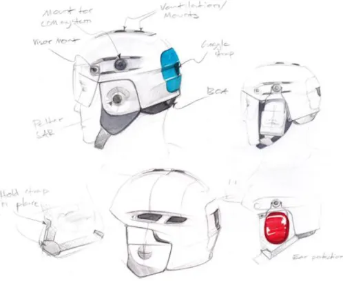
4.3.3.1 Droptest... 39 4.4 CONCEPT GENERATION... 41 4.4.1 Brainstorming ... 41 4.4.2 Moodboards ... 41 4.4.3 Speed sketching ... 43 4.4.4 Exploratory sketching ... 43
4.4.5 Feedback from HOWL design studio ... 44
4.5 FURTHER DEVELOPMENT ... 45 4.5.1 Refined sketching ... 45 4.5.2 Mount concepts ... 46 4.6 PROTOTYPING ... 47 4.6.1 Clay models ... 47 4.6.2 Digital prototypes ... 47 4.6.2.1 Form ... 48
10
4.6.2.3 Materials and manufacturing ... 51
4.7 CONCEPT EVALUATION ... 51 4.7.1 SAR ... 51 4.7.2 SSRS ... 51 4.7.3 HOWL ... 52 4.7.4 Baering ... 53 4.7.5 Concept evaluation ... 53 4.8 FURTHER REFINEMENT ... 54 4.8.1 Mount concept ... 55
4.8.1.1 Flush ACH-ARC rail ... 55
4.8.1.2 Picatinny snap mount ... 56
4.8.1.3 Flexi snap mount ... 56
4.8.1.4 Mount Evaluation ... 57 4.9 MIPS ... 59 4.10 PRODUCTION R1 HELMET ... 60 4.10.1.1 Manufacturing process ... 61 4.10.1.2 Injection moulding ... 61 4.10.1.3 Thermoforming ... 62 5 RESULTS ... 63 5.1 R1-RESCUE ONE HELMET ... 63 5.1.1 Ergonomics ... 63 5.1.2 Standards ... 64 5.2 HELMET COMPONENTS ... 65 5.2.1 Outer shell ... 65 5.2.2 Inner liner ... 67
5.2.3 Ear covers and chin strap ... 69
5.2.4 Communication system ... 72
5.2.5 Retention system ... 73
5.2.6 Mount concept ... 74
5.2.7 Half integrated top light ... 74
5.2.8 Eye shield ... 75 5.2.9 Visor concept ... 76 5.3 PHYSICAL PROTOTYPE ... 77 5.3.1 Outer shell ... 77 5.3.1.1 Milling ... 77 5.3.1.2 Vacuum forming ... 79 5.3.2 Liners ... 80 5.3.3 Mounts ... 83 5.3.4 Assembly ... 83
5.3.5 Estimated cost calculation... 84
5.4 TESTING ... 85
5.4.1 Testing at MIPS... 85
5.4.1.1 Testing ... 86
6 DISCUSSION AND CONCLUSIONS ... 89
6.1 PROCESS ... 89
6.2 Y1 EVALUATION ... 89
6.3 USER CENTRED DESIGN... 89
6.4 MATERIAL CHOICE ... 90
6.5 MANUFACTURING ... 90
6.6 PHYSICAL TESTING ... 90
6.7 FINAL RESULT ... 91
7 RECOMMENDATIONS AND FUTURE WORK ... 92
7.1 POTENTIAL MANUFACTURERS ... 92
7.2 MOUNT TESTING ... 92
7.4 FURTHER TESTING ... 92
7.5 FIELD TESTING ... 92
7.6 REFINE DESIGN ... 92
7.7 FINAL EVALUATION ... 93
7.8 CERTIFICATION AND MANUFACTURING ... 93
8 REFERENCES ... 94
9 APPENDIX ... 98
APPENDIX A-PROJECT PLAN ... 99
APPENDIX B-GANTT-SCHEME ... 103
APPENDIX C-FOLKSAM HELMET TEST RESULTS ... 106
APPENDIX D-STANDARD EVALUATION ... 107
APPENDIX E–TEST METHOD DESCRIPTION ... 109
APPENDIX F-COMPETITOR ANALYSIS ... 111
APPENDIX G–JENS ARPRO, SUGGESTED ADHESIVES ... 113
APPENDIX H–WORKSHOP SAR,Y1 EVALUATION ... 114
APPENDIX I-DESIGN GUIDELINE ... 116
APPENDIX J–INTERVIEW MIKAEL SWAREN ... 118
APPENDIX K–MATERIAL PROPERTIES ... 120
APPENDIX L–MATERIAL BENCHMARK ... 122
APPENDIX M-UNDERLAY ... 123
APPENDIX N-HOWL MEETING ... 124
APPENDIX O–SARCONCEPT EVALUATION ... 126
APPENDIX P–HOWL CONCEPT EVALUATION ... 127
APPENDIX Q–COMPANIES CONTACTED ... 130
APPENDIX R–THERMOFORMING GUIDE ... 131
APPENDIX S–MIPS TEST PLAN ... 132
1
1 INTRODUCTION
The project background, purpose and delimitations are presented in this chapter.1.1 Background
Search and rescue personnel lack head protection that is purposely designed for their profession and needs. The rescue personnel are mainly working at sea, operating from boats, ships and helicopters. There are approximately 2000 active search and rescue workers in Sweden.
Helmets designed for outdoor sports, such as rafting and mountain climbing, are used as substitutes. Required functions such as position lights and communication systems have to be retrofit, often with make-shift solutions using cable ties, tape or Velcro. A common helmet is the Predator helmet, a rafting helmet, used by Search and Rescue, SAR, in Norrtälje. These helmets lack desired properties and functions to meet their standards.
User studies conducted in MF2061 project, year 2013, indicated problems with these custom mounting solutions. The retrofit components protrude from the helmet and can interfere with ropes, wires and other rescue equipment. This is a safety concern especially among rescue workers that operate from helicopters.
A concept of a search and rescue helmet, named the Y1, was developed in collaboration with Baering as part of a higher course project in 2013. The result was a full-scale model of the helmet, purposely designed for rescue personnel, see
Figure 1.
2
1.2 Purpose
In this thesis project, the Y1 concept is evaluated and further developed with the aim of presenting a production ready helmet, the R1, Rescue One.
The project will begin with an evaluation of the Y1 concept in conjunction with Baering and Howl Design Studio. User interviews will be carried out to identify areas of further development. Research will be conducted on materials, manufacturing methods, safety standards and external components. The manufacturing methods will be benchmarked based on cost and efficiency. The materials will be physically tested according to the existing safety standards.
1.2.1 Deliverables:
A user-friendly design according to anthropometric data and ergonomic guidelines.
Highly detailed CAD models, with accurate dimensions and materials, designed for manufacturing
A prototype with high degree of functionality and correct materials
1.2.2 Delimitations
Integrated electronic components
Prototype helmets in different sizes will not be considered due to time limitations.
Field testing of helmets and practical evaluation of mounted components will not be performed.
3
2 METHODS
This chapter explains the methods used throughout the project, from acquisition of data to concept development and evaluation.2.1 Iterative design process
Iterative design process is a design methodology, a cyclic process of prototyping, analysing, testing and refining. The method involves the users in several stages of the design process, to avoid problems and to correct them as soon as they emerge. Designs and prototypes are presented and the feedback given is used to further develop the design/prototype. This is mostly beneficial when it starts as early as possible in the design process to avoid unnecessary costs and too many irrelevant prototypes. (Schneider, J., & Stickdorn, M. (Eds.), 2011, ss. 124- 135)
Stage one of the process is to create a better understanding of the user and product.
Second stage is about creating concepts, prototypes.
Third stage evaluation, testing and analysing
Last stage is to implement the feedback and information gathered from stage three and refines the concepts or prototypes.
2.2 Project planning methods
A well-planned project is essential for achieving a good result. A project plan is created to provide an overview and clarify the important aspects of the project. A time plan is created and visualized with a Gantt-chart.
2.2.1 Project plan
The project plan is to clearly communicate the structure in the project through categorizing and describing each task. The project plan is divided into main and sub-categories.
2.2.2 GANTT-chart
Gantt-chart is used to structure the project plan and plan each task for a larger time limited project. The chart is divided into a horizontal timeline on one axis and a vertical axis with a list of chronological ordered tasks. Each task illustrated with a bar that represents the duration of time.(Johannesson, H., Persson, J-G., & Pettersson, D., 2004)
2.3 Information retrieval
Information is gathered to gain insight in areas of interest and background. The information is gathered through different methods, such as statistics, literature, articles, internet forums, websites etc.
4
2.4 Competitor analysis
A competitor analysis is conducted to analyse the market with focus on trends, key success factors in order to further understand the product and identify opportunities for improvement(Bergman, B. and Klefsjö, B., 2010). The analysis includes research regarding material, construction, standards and ergonomics of the product.
2.5 Material analysis
A material analysis performed together with the competitor analysis, concerning impact properties and shock absorption effectiveness to analyse which material that is of interest for the R1 helmet. To further analyse and benchmark the materials, the software CES EduPack is used to obtain comparable data.
2.6 Semi-structured interviews
An interview is a qualitative method for obtaining information. It is as structured conversation between the person conducting the interview and the interviewee. The objective is to uncover the interviewee’s personal view and opinion on a certain subject by asking predetermined questions. A semi-structured interview differs from a regular interview by being more open for discussion and allowing both the interviewer and interviewee to elaborate on thoughts and ideas(Gill, Stewart, Treasure, & Chadwick, 2008).
2.7 Ideation workshop
An ideation workshop is a method where the participants discuss a certain subject and collaborate to produce ideas. The method allows the participants to express themselves more freely by playing out scenarios and list problems by exploring the gap between existing and future products. The workshop method in this project has been used in a way to explore the existing solution and implement scenarios for further development(Sharples, Giasemi, Vavoula, & Mike, December 2007).
2.8 Focus group
Focus groups are a group of people selected to represent the targeted demographic. A focus group is used to determine the customers' needs and find the problems with current solutions. The goal with this method is to both help the developers generate new ideas and evaluate alternatives (Ullman, 2010, p. 152).
2.9 Ideation
Ideation is the process of generating different solutions and designs. Different methods were used in the different stages of the development process.
2.9.1 Brainstorming
Brainstorming is a method used for generating new ideas. It is typically a group activity, but can be performed individually as well. Brainstorming is often focused on a specific theme or
5 function, with the purpose of generating as many ideas as possible within a certain time frame(Ullman, 2010, p. 190).
The brainstorming activity is usually divided in multiple sessions for each subject. In a group setting, the individual members generate ideas separately and share their work with the rest of the group at the end of a session. The purpose of sharing ideas is to trigger new ideas from other group members. In order not to limit creativity, placing judgment and negative criticism is not allowed during the sharing process. When all ideas have been presented, the entire process is then repeated.
According to Ullman, the four rules for brainstorming are:
1. Record all the ideas generated. Appoint someone as secretary at the beginning; this person should also be a contributor
2. Generate as many ideas as possible, and then verbalize these ideas 3. Think wild. Silly, impossible ideas sometimes lead to useful ideas.
4. Do not allow evaluation of the ideas; just the generation of them. This is very important. Ignore any evaluation, judgment, or other comments on the value of an idea and chastise the source.
2.9.2 Moodboard
A moodboard is a collection of images on a board that is put together to illustrate a certain mood where the purpose is to inspire the designers and communicate the direction of the product.
2.9.3 Speed sketching
Speed sketching is a method used to help produce large quantities of sketches in a brief limited time. Underlays can be used as templates during the sketching process to help the designer preserve the correct proportions, while maintaining the sketching speed(Sjölen, K., & Macdonald, A, 2011).
2.9.4 Exploratory sketching
Exploratory sketching is a method for both generating and exploring ideas and solutions. The sketches are quick and simple with focus on function. The aim is to generate as many ideas as possible(Sjölén, 2005).
2.10 Evaluation
Evaluation methods are used to benchmark and analyse different solutions, such as concepts and competitors.
2.10.1 Pugh-matrix
The Pugh-matrix is a method used for weighing different concepts, ideas or products against each other based on pre-defined performance criteria’s. Often a reference concept or product is used with a neutral score. The items for comparison attain a relative score to the reference
6
product. The Pugh-matrix provides a visual overview of which concept that meets the stated criteria best(Ullman, 2010, pp. 221-229).
2.10.2 SWOT-analysis
SWOT analysis is a structured method used to evaluate the strengths, weaknesses, opportunities and threats in a project. The objective of the project is specified and the internal and external factors are identified as positive or negative depending on how they can potentially influence the result(Ullman, 2010, pp. 101-102).
2.10.3 Clay model
Clay models are used for translating 2D sketches and digital designs into physical 3D volumes. InDeClay and SuperClay are two types of clay purposely developed by Kolb Technologies for industrial designers and form exploration. The properties of the clay allow the designer to process the clay manually and make immediate adjustments by adding and removing material(Clay).
2.10.4 CAD
Computer Aided Design is used for producing digital prototypes of designs and generating drawings for manufacturing. The dimensions can be precisely controlled in a CAD environment.
2.10.5 Physical prototype
Physical prototypes are created to test and evaluate the product and or manufacturing method. The prototypes can be created to evaluate the concept, product, process or production(Ullman, 2010, p. 118). The aim with these physical prototypes in this project is to evaluate the concept together with the users. The secondary aim is to evaluate the manufacturing and production process if possible.
7
3 FRAME OF REFERENCE
The reference frame is a summary of the existing knowledge and former performed research on the subject and new findings.3.1 Project plan
The project plan was divided into five phases and each phase is divided into main and sub branches.
1. Phase one emphasizes on planning the project and evaluating the previous Y1 concept. 2. Phase two includes research and analysis of the market today
3. Phase three is about concept development and benchmarking 4. Phase four is refinement, prototyping and testing
5. Phase five is presentation
See Appendix A for complete project plan. The project plan translated into a Gantt-chart, illustrating each task duration related to time, see Appendix B.
3.2 User groups
The information gathered trough observations and interviews during the higher course project MF2061, led to two main user groups SAR and SSRS.
3.2.1 SAR
The Swedish Search and Rescue, SAR, governed by the Swedish Maritime Administration is responsible for sea rescue, including coastal areas around the lakes Vättern and Vänern. SAR operates from 15 bases in Sweden with helicopters. They have crew on stand-by, ready to dispatch within 15 minutes(Sjö- och flygräddning, 2014).
A helicopter rescue crew typically consists of four people; two pilots, a winch operator and a rescue swimmer. In a rescue situation, the rescue swimmer is lowered and raised from the helicopter using a wire rope and winch, see Figure 2. The rescue swimmer's objective is to reach the distressed as quickly as possible and bring them back to safety in the helicopter.
8
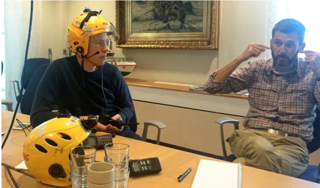
The rescue swimmer must be able to communicate with the helicopter crew at all times and does so using a top mounted position light and a two way radio communication system. Furthermore, the rescue swimmer also relies on additional lights pointing in the field of view in low light situations.
SAR currently uses helmets on which external components are attached to accommodate these functions. A commonly used helmet is the Predator Full Cut, as seen in Figure 3. The Predator helmet is not purposely designed for the rescue swimmer's needs and has to be physically modified to enable mounting of components.
Figure 3. Predator helmet with mounted position and spotlights.
Interviews and workshops conducted in the MF2061 project revealed that the lights and other components mounted on the helmet risk getting in the way of the wire rope, resulting either in entangling the rescue swimmer or breaking loose from the helmet. The height inside the helicopter when seated is also limited for top mounted components.
SAR requested a more compact helmet design that minimizes the interference with the wire rope while still maintaining the same functionality.
3.2.2 SSRS
The Swedish Sea Rescue Society, SSRS, is a non-profit association with the objective of saving lives at sea. SSRS consists of 2000 volunteer members who operate from 67 stations along the Swedish coastline. Each year they receive over 7000 distress calls and are ready to respond within 15 minutes(Vi räddar liv till sjöss, 2014).
SSRS typically operate in less favourable and demanding weather conditions, with strong winds and high seas. The rescue personnel are heavily dependent on their rescue equipment and demand the highest level of quality and reliability. SSRS have 103 ships to their disposal; ranging from large cruisers to small boats, 15 hovercrafts and 45 rescue runners. The rescuerunner, as seen in Figure 4, is a purposely designed jet ski that can reach speeds up to 34 knots, or 63 km/h(Våra båtar, 2014).
9 Figure 4. SSRS Rescuerunner in action.[2]
During a rescue operation, safety and communication is essential to quickly locate the distressed and bring them to safety. User studies conducted in the MF2061 project course revealed that the helmet is a key piece of equipment for personal safety and for providing visual and radio communication.
Helmets such as the aforementioned Predator Full Cut and the Gecko Open Face are retrofit with radio speakers, lights and reflective tape. Visors are used in addition to prevent water from splashing directly in the eyes, especially under windy conditions and when travelling at high speeds over water.
SSRS found the current solution inadequate in terms of ability of attaching third party components, safety and ergonomics. The components are typically mounted using Velcro and cable ties. In some instances, the hard outer shell of the helmet needs to be modified and holes are made. This may compromise the structural integrity of the helmet and the safety of the user as a result. SSRS also experienced that there is a lack of helmets that take extra large head sizes and different head shapes in consideration.
3.3 Ergonomics
One of the important and unsolved matters according to SSRS personnel was the ergonomics in the helmets today. Head sizing and relative aspects for a comfortable helmet is presented below.
3.3.1 Head sizes
Different head sizes and shapes were taken in consideration when designing the R1 helmet. Most of today's helmet manufacturers offer different sizes for the purpose of providing better fit. In contrast, helmets that only come in one size, such as the Predator Full Cut, compensate for different sizes by using additional padding, resulting in the user having to carry more weight.
10
Helmet size is measured in head circumference, in the transverse plane over the temple, as seen in Figure 5. The dimensions are derived from the EN 960:1995 standard, as referred to in the PAS 028 standard.
Figure 5. Section of vertical longitudinal plane. Circumference measured in plane marked with 2. [3] The EN960 standard describes the standardized head mannequins used in testing of protective helmets. The dimensions are based on anthropometric data and translated into 15 nominal sizes, spanning from the 5th percentile female to 95th percentile male. Five common head mannequin sizes are presented in Table 1 below(Ball, 2011).
Table 1: Head form sizes with circumference.
Size Delta Y [mm] Delta X [mm] Mass [grams] Circumference [mm]
A 89,5 24 1525 +- 35 500
E 96 26 2050 +- 35 540
J 102,5 27,5 2885 +- 35 570
M 107 29 2950 +- 35 600
11
3.3.2 MIPS
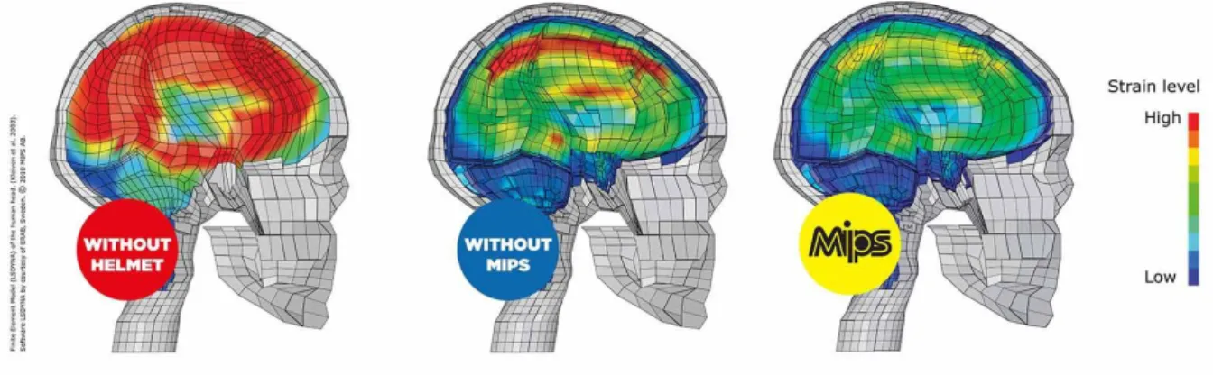
The Multi Impact Protection System, MIPS, is a patented technology developed by MIPS AB, with the aim of reducing rotational forces on the brain caused by angled impacts on the head. MIPS achieved this by mimicking the brain, which is naturally protected by a low friction fluid layer. MIPS introduces a low friction layer in the helmet that allows the helmet to slightly rotate relative to the head at impact(MIPS Helmet, 2014).
The results from simulations of a human brain in the event of an impact with and without MIPS can be seen in Figure 6.
Figure 6. A comparison of the forces affecting the brain in the event of an impact, with and without MIPS. [4] Stigson, H et al conducted a study for Folksam where they tested thirteen ski helmets. They performed three tests, one drop test on the crown of the helmet, one angled impact on the side and one on the top. The angled impacts were conducted to measure the rotational and translational forces subjected to the head. This is accomplished by letting the helmet and head form assembly accelerate vertically towards the ground while a steal plate accelerates horizontally along the ground. The system is adjusted so that the plate hits the helmet at a specific velocity(Stigson, Åman, Krafft, Kullgren, & Rizzi, 2014).
The helmets were dropped from 0,7 m, vertical velocity of 3.8 m/s, and the steel plate had a velocity of 6.3 m/s which results in a total velocity of 7.4 m/s. The study showed that only three helmets passed all three tests. The limit for translational acceleration that a head can be subjected to was 100g, see Appendix C for the helmets tested and their value(Stigson, Åman, Krafft, Kullgren, & Rizzi, 2014).
3.4 Essential helmet components
A helmet consists of essential components with different functions and properties. A brief description about each component, their main functions and common features are presented in the following chapter.
3.4.1 Outer shell
This part is generally created with composite materials such as fibreglass, carbon or aramid fibre hybrid or thermoplastics ABS, PC (Pierce, 2011). An in-mould outer shell is constructed by moulding the outer shell together with the foam. The result is a helmet that is lighter, better ventilated with larger degree of design freedom. Another method is to create a hard-shell construction, where the outer-shell and inner liner is created separately and glued together.
12
The hard shell construction is more robust, cheaper but heavier compared to an in-mould(Ambuske, Logan, & McManigal, 2012).
"The main purpose of the outer shell is to protect the users head from objects penetrating and distribute the impact over the inner liner/foam. Composite materials are generally better when it comes to penetration protection due to its higher stiffness than thermoplastics. Because of composite material properties the shell can be constructed thinner therefore, an overall lighter helmet compared to thermoplastics.”(Adson, Larsson, Matin, & Svensson, 2013)The cons with using composite materials is the high material cost and labour intensive manufacturing method( Granta Design Limited, 2014).
The benefit of having a thermoplastic helmet except the low production price is that the shell becomes more durable and elastic which distributes the lower impacts better than composite materials(Mills & Gilchrist, 1991).
3.4.2 Inner liner
The inner liner is generally made from expanded polystyrene (EPS). The primary function of this component is to absorb the remaining force of the impact and distribute the load and decelerate the users head during impact. There are two types of inner liners that either offer protection from high single impacts or low multiple impacts (Shuaeib F. , Hamouda, Wong, Umar, & Ahmed, 2007).
3.4.3 Comfort liner
The comfort liners provides both comfort and secures the fit for the user. The secondary function for comfort padding is to help against vibrations and smaller impacts. The comfort liner is usually made of a firm synthetic foam pad such as EVA or Low-density polyurethane, covered with a skin friendly fabric(SHOEI CO., LTD).
3.4.4 Chinstrap
The chinstrap is the part that secures the fit of the helmet and fulfils the strict strength requirements according to the standard set. The chinstrap can vary in width and colour depending on the standard. The chinstrap is usually made in a synthetic material and covered with foam for comfort.
3.4.5 Retention system
Retention systems are used to provide a better or to fit several head sizes. The retention system is usually constructed with a knob or belt system for adjusting the size. The system can be designed in various ways depending on how the fit should be adjusted, some helmets can be adjusted all around and others only at the back. The retention system is attached to the helmet with metal rivets or screws.
3.5 External components
13
3.5.1 Communication
Communication is an important component that rescue personnel need for effective fieldwork, especially in airborne rescue, where the communication between the ground people and air crew is essential.
Prior to radio communication, rescue personnel used hand signals. This was a time consuming and non-effective method, according to Per-Magnus from SAR. Per-Magnus also stated that although there are several communication systems available in the market, only few meet their specific demands.
Baering AB thinks that an integrated or semi-integrated communication system can add product value.
3.5.2 Eye protection
According to Thore Hagman and other SSRS personnel, some type of eye protection is needed because of cold air at high speed and water floods. They also mentioned that some prefer goggles instead of visor due to better fit and a wider range of options to choose from. The visor is commonly made of polycarbonate because of its strength and good transparency. In addition, the visor can be treated with water- and scratch-proof coating(Schadvoyn, 1997). The visor can be integrated with the helmet or as an external part that is attached to the helmet. The visor is available in different sizes; long visors to protect a bigger area of the face and smaller ones which are easier to manoeuvre and have lower weight.
3.5.3 Camera
“The cameras main function is to record the rescue crew out on the field, for further evaluation and feedback. The main demands are that the quality should be watchable and waterproof with an existing housing or without. In addition to the demands SAR personnel also desires camera functions that can enhance their effectiveness out on the field, like Wi-Fi streaming. Today the GoPro camera is commonly used in this line of work, due to its price related to functions and the robust build. When using the water case the locations of the buttons are easy to find due to their elevated positions. The downside of the GoPro camera is that it is big and bulging outwards from the helmet. The most common position they attach the camera is on the top of the helmet which is due to the standard mounts and need for the GoPro to be horizontal." (Adson, Larsson, Matin, & Svensson, 2013)
3.5.4 Snorkel
The snorkel is a tool commonly used by water rescue personnel. The snorkel needs to be able to move freely due to branches and wires that easily come between the snorkel and the helmet. SAR Norrtälje team prefers and promotes the aqua lung. Aqua lung Military is a snorkel well suited for SAR personnel, the snorkel is made out of a rubber neoprene material. The snorkel is shaped as a J-tube or a flex tube. A mask strap is connected to the snorkel for easily mounting the snorkel to any kind of underwater mask(Aqua Lung Military Snorkel).
14
3.6 Standards
Safety standards are looked into and compared to find suitable standards for the R1 helmet. Test methods and criteria’s that need to be taken into account when developing the helmet are evaluated.
3.6.1 Helmet standards
The main function of a helmet is to protect the wearer from impacts by preventing penetration and absorbing force generated at impact. The helmet should be positioned correctly on the head to avoid unnecessary risks. The weight should be as low as possible to prevent strain in muscles over long term usage(SP, Technical Research Institute of Sweden).
Standards are created to verify and insure the user that the helmet follows the main functions. The standards also provide design guidelines for the developers and describe how the helmet should be tested with the corresponding failure thresholds(Ball, 2011, s. 307).
There are different standards due to different impact scenarios and severity of accidents. Additional tests that a standard may specify are water immersion, UV, retention system effectiveness. The differences between standards can be seen in Appendix D, where new and old standards are listed(CCID/Safety Unit, 2013).
There are some helmets today that follow a temporary standard, PAS 028, such as the Manta SAR and the Gecko helmet. PAS 028 is an interim standard because no British or European governing body have specified the performance criteria for rescue work. PAS 028 focuses on lifeboat rescue, therefore other standard certifications are added to fit the specific usage situation such as helicopter rescue, where airborne standard is needed(CCID/Safety Unit, 2013).
Some other standards that are common among search and rescue helmets are:
BSI EN12492 – Mountaineering
BSI EN1385–White water sports
BSI EN 966 – Airborne sports 3.6.1.1 PAS 028
PAS 028 is the standard used for helmets in maritime applications such as water rescue(PAS 028:2002, 2002). The standard states both design restrictions and testing methods. The requirements that affect the design are taken into account at this stage.
The materials of the helmet should not deteriorate from Ageing, exposure to sun, extreme temperatures and exposure to salt/fresh water.
Metal parts on the helmet should be resistant to corrosion on exposure to salt water.
The parts on the helmet that comes in contact with the skin should not undergo alterations from the effect of sweat and toiletries.
The shell should not extend more than 10 mm from the inner liner.
The helmet should protect the wearer at least to the FF” plane see Figure 7.
All edges should be smooth and rounded.
Rigid projections on the inside of the helmet are not allowed.
15
The retention system should always be fixed on the helmet together with a chin strap
The chin strap shall not be less than 18 mm wide.
The mass of the helmet shall not be more than 700 grams.
A peak is not allowed to be integrated with the helmet.
Figure 7. Extent of protection and wearing position. [5] 3.6.1.2 Testing according to PAS 028
Different tests are carried out to test the construction and design of the developed helmet. The test methods and thresholds are designed to imitate the working conditions of the helmet, see Table 2. The drop height and striker weight have a direct correlations with the head form used. The drop height shall be set to give a nominal impact energy, the height can be calculated with Eq.(1) and (2).
𝐸
𝑃= 𝑚 ∙ 𝑔 ∙ ℎ
(1)
ℎ =
𝐸𝑃𝑚∙𝑔
(2)
The rigid mode method is performed to measure the force transmitted to rigidly mounted head form on which a helmet is fitted, where the force transmitted to the head form shall not exceed 12,5kN. A weight is dropped from a specific height on to the rigidly mounted helmet. The falling head-form test is performed by placing the helmet on a head form, according to EN 960, equipped with accelerometers, which in turn is placed upside down and dropped from a measured distance on to an anvil. The anvil can be flat, round or other shapes such as curb stone. The deceleration shall not exceed 250g at any time and the total time when the deceleration exceeds 150g shall not be longer than 5ms.
The penetration test is performed in the same way as the rigid mode method but differs in head form and the striker used. The point of the striker shall not get in contact with the head form. See
Table 2for test methods.
Table 2: The different tests and their specific threshold according to PAS 028.
Striker weight Drop weight
Impact energy
Failure threshold
16
Falling head form method (Crown impact)
The weight of the head form
(4,7 kg for head form J)
0,33 m 15 J 250g
Rigid mode (Crown
impact) 5,0 kg 2,0 m 100 J 12,5 kN
Rigid mode method
(Off-crown impact) 5,0 kg 0,5 m 25 J 12,5 kN Resistance to penetration (crown impact) 1,5 kg 2,0 m No contact with head form Resistance to penetration (Off-crown impact) 3,0 kg 0,5 m No contact with head form
See Appendix E for full description of each test method(PAS 028:2002, 2002).
3.6.2 Component standards
The working conditions for a rescue member are different depending on what type of field work they specify in. SAR and SSRS are known to work in wet and water conditions, which restricts them a bit when buying a component. A classification, IPXX, is used to rate an electronic equipment environmental protection. IP stands for ingress protection, where the IP number stands for how good the electronic equipment is enclosed. The first number represents the protection extent from solid objects and materials, see
Table 3. The second number lists the protection against liquids criteria’s see Table 4. For working conditions like search and rescue the components would need at least a IPX7 standard which allows the component to be underwater up to 1 m for 30 min. The standard aims to give the user a better understanding than the vague marketing terms, such as waterproof.
Table 3: First number designation in IP standard.
0 - No protection (Sometimes X)
1 - Protected against solid objects up to 50mm³ 2 - Protected against solid objects up to 12mm³ 3 - Protected against solid objects up to 2.5mm³ 4 - Protected against solid objects up to 1mm³
5 - Protected against dust, limited ingress (no harmful deposit)
6 - Totally protected against dust
Table 4: Second number designation in IP standard.
17
1 - Protection against vertically falling drops of water (e.g. condensation) 2 - Protection against direct sprays of water up to 15 degrees from vertical 3 - Protection against direct sprays of water up to 60 degrees from vertical
4 - Protection against water sprayed from all directions - limited ingress permitted 5 - Protected against low pressure jets of water from all directions - limited ingress
permitted
6 - Protected against low pressure jets of water, limited ingress permitted (e.g. ship deck)
7 - Protected against the effect of immersion between 15cm and 1m
8 - Protected against long periods of immersion under pressure
3.7 Competitor analysis
Rescue helmets are relatively new to the market and no official standard has been created. A helmet market research was conducted to further understand the essentials of a helmet, construction, modularity and features the helmet developers value when designing a helmet. The research consists mainly of helmets developed for rescue work but also other helmets that can be used due to their standards or functionality. See Appendix F for the complete helmet market research.
3.7.1 Main competitors
The most common helmets that are used by rescue members today according to SSRS and SAR members, some of the helmets are developed specifically to meet the rescue members needs while some have low weight and or easily modifiable.
3.7.1.1 Predator
“The most well-known helmet that Search and Rescue personnel at Norrtälje use is the Predator helmet, see Figure 8. The predator helmet follows the standard EN1385 helmets for canoeing. Used by the search and rescue members because of its low price and weight. They also liked that the helmet has a snug look."(Adson, Larsson, Matin, & Svensson, 2013)
The Predator helmet was purchased for further investigation, the thickness and fit was evaluated. The Predator helmet uses a 3mm thick ABS plastic as its outer shell glued together with a 15 mm inner liner, made of closed EVA foam. The button/belt retention system requires two hands and for the helmet to be removed for adjusting, according to SAR at Norrtälje(Predator helmet, 2010).
18
Figure 8. Predator Full Cut helmet. [6] 3.7.1.2 Gecko
“The Gecko helmet is one of the first helmets that were designed for search and rescue personnel, see Figure 9. The Gecko has built in attachment points for visor and camera mounts, bought separately. The overall weight is around 720 grams without exterior components as cameras and or visor. The inner liner of the helmet is constructed in EPS. The helmet has an inflatable liner, which gives the user better control over the helmet fit. A specific intercom can be placed inside the helmet. The outer shell is constructed in Kevlar fibreglass. The helmet is BSI approved to PAS 028: 2002 MSHS(Gecko Headgear Ltd, 2014).“(Adson, Larsson, Matin, & Svensson, 2013)
Figure 9. Gecko Marine Safety Helmet. [7] 3.7.1.3 Manta Hi-Viz SAR Multi-Role Helmet
The Manta SAR helmet is designed for a wide range of safety standards including PAS 028. The helmet has built in visor and attachment points for external visors and ear protectors, see Figure 10. The helmet has a knob controlled retention system, easily adjusted with one hand(Pbi Height Safety Limited, 2014).
19 The helmet follows seven standards that are:
EN14052:2005 High performance safety helmet PAS 028:2002 Marine safety helmet
FS/1 Quad & ATV helmet EN1384 Equestrian helmet
EN352-3:1997 Hearing protection EN166:2002 Industrial eye protection
EN12492 Working at height / Mountaineering
Figure 10. Manta SAR Multi-purpose helmet. [8]
The Manta SAR Helmet uses a 3-6 mm thick high impact ABS shell combined with an 18-22 mm thick inner liner, giving a total weight of 550 grams. (Pbi Height Safety Limited, 2014) 3.7.1.4 OPS-core FAST
A newly developed helmet designed according to the well-used military helmet OPS-Core see Figure 11. The use of ACH-ARC rail system gives the user possibilities to mount all sorts of components that the military uses today with no need of screws or other means that could degenerate the helmet.
20
Figure 11. OPS Core Fast helmet. [9]
The base jump model, the cheapest one, is made of polycarbonate with a NVG mount moulded together with the shell. The inner liner consists of EPP combined with LDV, low density vinyl, a closed cell foam for comfort. The liner is divided into smaller parts placed strategically around the helmet. The helmet has a retention system with a knob at the back for easy adjustments. The system is constructed in a way that tightens all around the helmet by turning the knob(Ops-Core, Inc)
3.8 Materials
In this section materials are presented and how they act in the context.
3.8.1 Outer shell
The material of the outer shell depends on what type of demands there are and the degree of protection that the helmet should follow.
3.8.1.1 Composite shell
Less material is needed to achieve the desired amount of protection compared to a thermoplastic helmet, because of the materials high stiffness and strength, resulting in a lighter helmet. A composite shell can be very beneficial, for instance when designing a MC-helmet where the weight, single high impact and penetration protection are key features. On impact, the composite shell crumples, cracks and delaminates which reduces the impact force transferred to the helmet liner (Mills & Gilchrist, 1991). The composite shells are usually constructed in multiple layers of fibres inside a mould, by adding resin and heat, the material hardens( Granta Design Limited, 2014).
21 3.8.1.2 ABS
As for a search and rescue helmet where multiple impacts are common a more flexible material is beneficial, for instance ABS plastic. These kinds of shells can upon impact flex and therefore distribute the impact force better on to the inner liner. ABS, also called acrylonitrile-butadiene styrene, has good impact properties and cost-effective manufacturing processes(Caswell, Gould, & Wiggins, 2007, pp. 95-99).The cons of using ABS is that it degrades with time when exposed to UV. The UV properties is improved by adding UV stabilizers in the moulding process or adding a UV protective coating afterwards ( Granta Design Limited, 2014). ABS has lower stiffness then composite material and therefore a thicker shell is needed to pass the penetration impacts, which also makes the shell heavier than composite shell.
3.8.1.3 PC
Polycarbonate, PC, has the advantage of withstanding higher temperatures than ABS which makes it possible to create in moulded helmets due to the high moulding temperature of EPS/EPP. ABS provides good impact strength, but when a material with higher impact strength and better engineering properties are needed, polycarbonate is recommended. The disadvantages with using polycarbonate are the material's bad chemical resistance and notch resistance(Caswell, Gould, & Wiggins, 2007).
3.8.2 Inner liner
Very few materials are known to be used as an inner liner. Lately some new materials have been tested and evaluated, such as Koroyd, but can be expensive due to high material and manufacturing cost. Baering stated that a less expensive material should be used, as a result from the previous project.
3.8.2.1 EPS
EPS is the most commonly used liner due to its good shock absorbing properties, low cost and ease of manufacture. The liner is compressed and permanently deformed when absorbing even a low impact. The EPP and helmet is therefore disposed of after the impact (Caswell, Gould, & Wiggins, 2007).A lower density EPS has the properties to be softer and lighter but does not protect against high impacts. While a higher density has higher weight, it can protect against bugger impacts with a thinner liner. Some helmets today has a combined EPS density line, which means that they have one high density EPS together with one lower density EPS to create a helmet that can protect the wearer against a wider variety of impacts.
3.8.2.2 EPP
Almost the same as EPS foams, the big difference is that the EPP does not deform permanently in smaller impacts, which makes it possible for the helmet to withstand multiple impacts. The EPP is also a bit more expensive than the EPS( Granta Design Limited, 2014). In a low impact, the EPP material will compress to absorb the impact but returns to its original shape. In a high impact, the EPP will act more as EPS and deform a bit and almost return to its original shape. These kinds of liners are typically used in hockey helmets, due to repetitive impacts. Because the EPP does not crush during impact, less impact force can be absorbed and a higher density or thicker liner is needed for a higher demanding standard(Shuaeib F. , Hamouda, Wong, Umar, & Ahmed, 2007).
22
3.8.2.3 EVA
EVA foam liner is also known as a soft foam liner. These kinds of liners usually does not meet the specific requirements for a typical helmet according to Nina Faile's research for Creative Commons (Faile, 2011). This foam is usually combined with a hard plastic outer shell and thus a comfortable helmet with bearable protection against smaller impacts.
3.8.3 Inner liner and shell combination
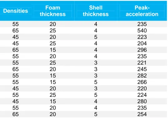
According to the design requirements, a multi impact liner is preferred. The material choice was therefore EPP. EPP is a bit harder to calculate compared to a standard EPS density calculations, due to that EPP stress-strain behaviour can be divided into three regions, linear elasticity, non-linear elasticity and densification. In a research paper conducted by F.M Shuaeib et al. (2007), a finite element simulations of drop tests was performed, with different EPP densities together with different thickness and varying ABS plastic thicknesses. According to Shaueib, the optimal helmet design would be EPP 55 kg/m3 with 15mm foam thickness and a 5mm ABS shell thickness. Table 5 shows different densities combined with different shell thickness, foam thickness and the resulting peak-acceleration(Shuaeib F. , Hamouda, Wong, Umar, & Ahmed, 2007).
Table 5: Peak acceleration as a function of shell and liner properties.
Densities Foam thickness Shell thickness Peak-acceleration 55 20 4 235 65 25 4 540 45 20 5 223 45 25 4 204 65 15 4 296 55 20 4 235 55 25 3 221 65 20 3 245 55 15 3 282 55 15 5 266 45 20 3 220 55 25 5 224 45 15 4 280 55 20 4 235 65 20 5 254
One important factor that SSRS personnel have been repeating is the weight, which is mainly determined by the outer shell. Shuaib mentioned in the paper that the thickness of the shell has a small effect on the peak acceleration. The thickness is mainly decided from the penetration resistance requirements (Shuaeib F. , Hamouda, Wong, Umar, & Ahmed, 2007). The shell should therefore be as thin as possible without compromising the penetration resistance requirement.
23
3.9 Manufacturing
The methods presented are those more relevant when developing a helmet. The method, pros and cons of each method and design recommendations are described.
3.9.1 Injection moulding
High tooling cost
Low unit cost
Suitable for high volume mass production
High surface finish
Highly repeatable process
Cycle time 30-60 sec
Almost all thermoplastic materials
The injection moulding process requires an injection moulding machine, raw plastic material and mould/moulds. Injection moulding according to CES EduPack is most beneficial when the annual quantity is at least 10 000 units per year.
The raw plastic material in melted in the injection forming machine and then injected into the mould, where the raw plastic material cools down and solidifies into the final product. See Figure 12, which illustrates process in more detail.( Granta Design Limited, 2014)
Figure 12. Process of injection moulding. [10]
General tips when designing for injection moulding, a uniform wall thickness throughout the part can minimize the sinking, warping, residual stresses and cycle times. Another tip is to use generous radius at all corners, provide draft on the part for easy removal and ease of closing and opening the moulds. The use of ribs, improves part stiffness in bending, this to avoid thick sections to achieve the same. This also saves weight, material costs and cycle time costs of the part(Custompart.Net, 2009).
24
3.9.2 Thermoforming
Low tooling costs
Moderate unit costs
Good surface finish
Good for prototype making and low volume productions
Tolerance of 0,4 %
Good with ABS, PS
A manufacturing method where a plastic sheet is heated and then formed into a specific mould( Granta Design Limited, 2014). Thus only controlling the side that touches the mould surface.
There are two main thermoforming methods used, the first and cheaper method is vacuum forming and the second method is high pressure-forming. The key advantages of using thermoforming is that it is cost-effective, low tooling cost, short lead time and the ability to create large parts(Lesko, 2008). Cost effective in a production with an annual quantity of 250- 3000units (Productive Plastics, Inc, 2014). One of the biggest disadvantages is that the thickness of the part is hard to control.
The cost is mostly dependent on what type of mould used and if the process is automated or not. There are positive and negative moulds where the positive mould is used for a better surface finish on the inside while the negative mould is used for a better finish on the outside surface.
3.9.2.1 Vacuum forming
Vacuum forming is the cheap and simplified version of thermoforming. The extruded plastic sheet is heated until the plastic is softened, then pressed against a 3D mould by vacuuming out the air between the plastic sheet and mould. Once the desired shape is achieved, the plastic is cooled and finally released from the mould. See Figure 13for an illustration of the vacuum moulding process(Lesko, 2008).
25 3.9.2.2 Pressure forming
Air pressure is used on the back side of the heated plastic sheet to assist the vacuum process to force it to the mould. See Figure 14for an illustration of the pressure forming process. The air pressure is usually between 50 psi up to 100 psi. The additional force makes it possible to form thicker sheets and achieve finer detail, textures, and sharp corners, on the surface facing the mould. The final product quality is very similar to an injection moulded part. Thus making pressure forming an alternative to injection moulding when the annual production quantities are under 10 000 units(Productive Plastics, Inc, 2014).
Figure 14. Process of pressure forming. [12] 3.9.2.3 Design recommendations
Peter Ljungberg from WETA-plast and Michael Gryvik from Arla-plast were contacted for a short phone interview regarding thermoforming recommendations. Questions regarding design that can facilitate a good thermoformed result were asked. Michael Gryvik mentioned a PDF document, A Vacuum Forming Guide, (Formech International Ltd, 2010), where it states several thermoforming recommendations and tips on moulding. An extract of the recommendations and tips are listed below:
Hygroscopic materials, ABS or PC, needs to be pre-dried. The material placed in a dryer and heated to the specific temperature during a specific time. Time and temperature depends on material choice.
The wall thickness can differ. To accommodate this, the sheet can be pre-stretched right before the vacuum is turned on.
A more expensive but more efficient way to control the thickness is to use a plug assist. A female and assisted male mould is used in combination, to cool the areas where most stretching would occur.
Undercuts are possible, but increases the tooling cost.
Big draft angles on the moulds edges for ease of release.
26
3.9.3 Expanded foam moulding
EPS and EPP are very similar materials when manufacturing. EPS and EPP foams are currently dominating the market, due to its good performance and lightweight properties. The manufacturing cost is low for large production quantities. The EPP and EPS consist of plastic cells that are bonded together in the desired shape. Foam helmets are generally made by expanded foam moulding.
There are two stages in the moulding process. It starts with solid polymer granules that are first softened and expanded by steam-heating under a small pressure. The softened granules are then transferred to an aluminium mould where the particles are steam heated at a higher pressure, making the particles expand to 20 or more times their original volume, fusing the particles and reshaping to the moulds design, Figure 15 shows an example of the process( Granta Design Limited, 2014). A typical mould for an EPP helmet liner has a core and cavity and the gap between them defines the shape of the helmet. The core is generally hemispherical in shape and configured to roughly match the shape of a human head.
Figure 15. Expanded foam moulding process. [13]
A problem encountered in manufacturing of EPP helmets is how to include complex shapes such as cut outs and holes for fasteners and ventilation in the moulding process. A method that is used for forming holes in EPP helmets is to cut the holes after moulding process with a hot knife or wire. The principal disadvantage to this procedure is that it can be extremely messy due to the EPP accumulating on the knife and around the workstation where the cutting is performed.
Another attempt made to efficiently mould holes into EPP helmets is to employ “sliding” core in which there are movable projection in the core, which correspond in size to the holes to be formed in the helmet. When moulding the helmet the projections are inserted into the void between the core and cavity before the beads are introduced into the mould. After the part

![Figure 11. OPS Core Fast helmet. [9]](https://thumb-eu.123doks.com/thumbv2/5dokorg/4620708.119242/36.892.274.614.146.509/figure-ops-core-fast-helmet.webp)
![Figure 12. Process of injection moulding. [10]](https://thumb-eu.123doks.com/thumbv2/5dokorg/4620708.119242/39.892.212.688.573.835/figure-process-of-injection-moulding.webp)
![Figure 16. OPS Core helmet in different configurations. [14]](https://thumb-eu.123doks.com/thumbv2/5dokorg/4620708.119242/44.892.289.604.166.506/figure-ops-core-helmet-in-different-configurations.webp)