Catalysts for Fuel Cell Vehicles
Development of Methanol-Reforming
Johan Agrell
Doctoral Thesis 2003
KTH – The Royal Institute of Technology Department of Chemical Engineering and Technology
Chemical Technology SE-100 44 Stockholm, Sweden
TRITA-KET R181 ISSN 1104-3466
ISRN KTH/KET/R--181--SE
A hydrogen-fuelled PEM fuel cell go-cart from Ballard. (All pictures were taken at the 7th Grove Fuel Cell
Symposium, September 11-13, 2001, London, UK)
A close-up of the PEM fuel cell go-cart from Ballard.
A fuel cell-powered pick-up truck from GM. The system incorporates a high-temperature gasoline reformer for H2
Abstract
Vehicles powered by proton exchange membrane (PEM) fuel cells are approaching commercialisation. Being inherently clean and efficient sources of power, fuel cells constitute a sustainable alternative to internal combustion engines to meet future low-emission legislation. The PEM fuel cell may be fuelled directly by hydrogen, but other alternatives appear more attractive at present, due to problems related to the production, transportation and handling of hydrogen.
Fuelling with an alcohol fuel, such as methanol, which is oxidised directly at the anode, offers certain advantages. However, the efficiency of the direct-methanol fuel cell (DMFC) is still significantly lower than that of the conventional hydrogen-fuelled PEM fuel cell, due to some technical problems remaining unsolved. Hence, indirect fuelling by a reformed liquid fuel may be the most feasible option in the early stages of the introduction of fuel cell vehicles.
The work presented in this thesis concerns the development of catalysts for production of hydrogen from methanol by partial oxidation, steam reforming or a combination thereof. The work contributes to the understanding of how the preparation route affects catalyst morphology and how physicochemical properties determine catalytic behaviour and reaction pathways.
The thesis is a summary of seven papers published in scientific periodicals. The first paper (Paper I) reviews the current status of catalytic hydrogen generation from methanol, focusing on the fuel cell application. Paper II investigates the partial oxidation of methanol over Cu/ZnO catalysts prepared in microemulsion and by a conventional co-precipitation technique. The activity for methanol conversion in the low-temperature regime is found to be significantly higher over the former materials and the work continues by determining the nature of possible Cu-ZnO interactions in the catalysts by studying their physicochemical properties more thoroughly (Paper III). In Paper IV, the pathways for methanol conversion via both partial oxidation and steam reforming are elucidated.
In Paper V, partial oxidation of methanol is studied over Pd/ZnO catalysts prepared by microemulsion technique and again compared to conventional materials. This investigation demonstrates that although possessing high methanol conversion activity, palladium-based catalysts are not suitable for reforming in fuel cell applications due to the considerable amounts of carbon monoxide formed.
In Paper VI, methanol reforming is investigated over a commercial Cu/ZnO/Al2O3
catalyst. The mechanisms for carbon monoxide formation and strategies for its suppression are discussed, as well as reactor design aspects. The study also includes some simple kinetic modelling. Finally, Paper VII describes the optimisation of catalyst composition and process conditions to reach high hydrogen production efficiency at low operating temperatures and with minimum carbon monoxide formation.
Keywords: PEM fuel cells, hydrogen, methanol, reforming, (partial) oxidation, reaction pathways, carbon monoxide, catalyst, microemulsion, Cu/ZnO, Pd/ZnO, copper, redox properties, oxidation state
Sammanfattning
Bränsleceller alstrar elektrisk energi med hög verkningsgrad och låga utsläpp. De utgör därför ett mycket intressant alternativ till förbränningsmotorer i bilar och andra transportmedel. Bränsleceller, där elektrolyten består av ett polymermembran, är i dags-läget högaktuella för just fordonstillämpningar. De kan drivas direkt av vätgas, men andra bränslealternativ framstår för närvarande som mer gynnsamma på grund av svårigheter i samband med framställning, transport och hantering av vätgas.
Oxidation av ett alkoholbränsle, till exempel metanol, direkt vid anoden är ett alternativ som erbjuder vissa fördelar. Verkningsgraden är dock än så länge betydligt lägre än vid direkt vätgasdrift. Framställning av vätgas ur ett vätskeformigt bränsle utanför bränsle-cellen framstår därför som ett intressantare alternativ, åtminstone under en övergångs-period till ren vätgasdrift eller direkt oxidation av metanol med acceptabel verkningsgrad. Avhandlingen beskriver ett arbete som utförts i syfte att utveckla och optimera katalysatorer för framställning av vätgas ur metanol under de förhållanden som råder i en bränslecelldriven bil. Den är en sammanfattning av sju artiklar som har publicerats i olika vetenskapliga tidskrifter. Avhandlingen bidrar till grundläggande förståelse för hur tillverkningen av en katalysator påverkar dess fysikaliska egenskaper och hur dessa i sin tur bidrar till katalytisk aktivitet och selektivitet.
Den första publikationen (Artikel I) ger en översikt av olika processer för produktion av vätgas från metanol. I Artikel II undersöks framställning av vätgas genom partiell oxidation av metanol med katalysatorer bestående av Cu/ZnO och tillverkade med hjälp av mikroemulsionsteknik. Dessa material uppvisar hög aktivitet för metanolomvandling vid låga temperaturer och eventuella synergier mellan koppar och zinkoxid undersöks därför mer ingående i en grundlig studie av materialens struktur och fysikaliska egen-skaper (Artikel III). I Artikel IV studeras reaktionsmekanismer för vätgasframställning genom både partiell oxidation och ångreformering.
I Artikel V undersöks partiell oxidation av metanol med katalysatorer bestående av Pd/ZnO, framställda med mikroemulsionsteknik. Trots att palladium uppvisar en hög aktivitet för omvandling av metanol vid relativt låga temperaturer, så är dessa katalysatorer olämpliga för reformering i bränslecelltillämpningar på grund av de avsevärda mängder kolmonoxid som bildas.
I Artikel VI beskrivs framställning av vätgas ur metanol med hjälp av en kommersiell katalysator. Mekanismer för bildning av kolmonoxid diskuteras ingående och förslag ges på hur denna biprodukt kan undvikas. Artikeln innehåller även enklare kinetisk modellering, samt idéer på olika reaktorlösningar. I Artikel VII optimeras slutligen katalysatorsammansättning och reaktionsbetingelser för att uppnå maximalt vätgasutbyte vid låg temperatur och med låga halter kolmonoxid.
Nyckelord: Bränsleceller, vätgas, metanol, reformering, (partiell) oxidation, reaktionsmekanismer, kolmonoxid, katalysator, mikroemulsion, Cu/ZnO, Pd/ZnO, koppar, ytegenskaper, oxidationstal
Publications referred to in the thesis
The work presented in this thesis is based on the following publications, referred to in the text by their Roman numerals. The papers are appended at the end of the thesis.
I. Catalytic hydrogen generation from methanol
J. Agrell, B. Lindström, L.J. Pettersson and S.G. Järås, in J.J. Spivey (Ed.), Catalysis – Specialist Periodical Reports, Vol. 16, Royal Soc. Chemistry, Cambridge, 2002, p. 67.
II. Production of hydrogen by partial oxidation of methanol over Cu/ZnO catalysts
prepared by microemulsion technique
J. Agrell, K. Hasselbo, K. Jansson, S.G. Järås and M. Boutonnet, Appl. Catal. A, 211 (2001) 239.
III. Production of hydrogen from methanol over binary Cu/ZnO catalysts.
Part I. Catalyst preparation and characterisation
J. Agrell, M. Boutonnet, I. Melián-Cabrera and J.L.G. Fierro, Appl. Catal. A, 253 (2003) 201.
IV. Production of hydrogen from methanol over binary Cu/ZnO catalysts.
Part II. Catalytic activity and reaction pathways
J. Agrell, M. Boutonnet and J.L.G. Fierro, Appl. Catal. A, 253 (2003) 213. V. Production of hydrogen by partial oxidation of methanol over ZnO-supported
palladium catalysts prepared by microemulsion technique
J. Agrell, G. Germani, S.G. Järås and M. Boutonnet, Appl. Catal. A, 242 (2003) 233. VI. Steam reforming of methanol over a Cu/ZnO/Al2O3 catalyst:
A kinetic analysis and strategies for suppression of CO formation
J. Agrell, H. Birgersson and M. Boutonnet, J. Power Sources, 106 (2002) 247. VII. Production of hydrogen from methanol over Cu/ZnO catalysts promoted by ZrO2
and Al2O3
J. Agrell, H. Birgersson, M. Boutonnet, I. Melián-Cabrera, R. M. Navarro and J.L.G. Fierro, J. Catal., 219 (2003) 389.
Table of contents
1 Introduction ... 1
1.1 Setting the scene... 1
1.2 Powering the cars of tomorrow ... 2
1.3 Scope of the thesis... 2
2 Fuel cells for clean power ... 3
2.1 The fuel cell... 3
2.1.1 Different types of fuel cells ... 4
2.1.2 The PEM fuel cell... 5
2.2 Fuel options ... 5
2.3 Fuel cell-powered vehicles... 7
2.3.1 Obstacles... 7
2.3.2 Environmental impact ... 8
3 Production of hydrogen from methanol ... 9
3.1 Processes for onboard hydrogen generation (Paper I) ... 9
3.1.1 Reaction pathways for methanol conversion... 10
3.1.2 Decomposition of methanol ... 10
3.1.3 Steam reforming of methanol... 11
3.1.4 Partial oxidation of methanol ... 11
3.1.5 Combined reforming of methanol ... 12
3.2 The fuel-processing system... 12
3.3 Reactor solutions ... 13
3.4 CO clean-up (Paper I) ... 14
3.4.1 Equilibrium CO content and water-gas shift... 15
3.4.2 Selective CO oxidation... 15
3.4.3 Methanation... 16
3.4.4 Palladium membranes ... 16
4 Catalysts ... 17
4.1 Catalyst development scope ... 17
4.2 Catalyst preparation... 18
4.2.1 Microemulsion technique ... 18
4.2.1.1 Microemulsions ... 19
4.2.1.2 Catalyst preparation in microemulsion... 19
4.3 Copper-based catalysts... 20
4.3.1 Binary Cu/ZnO catalysts prepared in microemulsion (Papers II and III) ... 21
4.3.1.1 Catalyst morphology... 21
4.3.1.2 Copper distribution... 22
4.3.2 Cu/ZnO catalysts promoted by Al2O3 and ZrO2 (Paper VII) ... 23
4.3.2.1 Catalyst morphology... 23
4.3.3 Catalyst stability and redox properties (Papers III and VII) ... 24
4.3.3.1 Temperature-programmed reduction... 26
4.3.3.2 Temperature-programmed oxidation... 27
4.4 Palladium-based catalysts (Paper V)... 31
4.4.1 Catalyst preparation... 31
4.4.2 Catalyst morphology ... 32
5 Catalytic behaviour ... 35
5.1. Experimental parameters... 35
5.1.1 The experimental set-up ... 35
5.1.2 Catalyst pre-treatment ... 36
5.1.3 Reaction conditions ... 36
5.2 Partial oxidation over copper catalysts... 37
5.2.1 The influence of catalyst preparation (Papers II and IV) ... 37
5.2.2 The influence of oxygen/methanol ratio (Paper II) ... 38
5.2.3 The reaction pathway for partial oxidation (Papers II and IV) ... 39
5.3 Partial oxidation over palladium catalysts (Paper V)... 41
5.3.1 Catalyst performance... 41
5.3.2 The reaction pathway for partial oxidation over palladium ... 43
5.4 Steam reforming over copper catalysts ... 44
5.4.1 Catalyst performance (Papers IV, VI and VII)... 45
5.4.2 The influence of catalyst structure (Papers IV and VII) ... 45
5.4.3 The reaction pathway and mechanisms for CO formation (Paper VI)... 46
5.4.4 A simple kinetic model (Paper VI)... 48
5.5 Combined reforming over copper catalysts ... 49
5.5.1 The influence of catalyst promotion (Paper VII) ... 50
5.5.2 The reaction pathway for combined reforming (Papers VI and VII) ... 51
5.6 Surface properties and catalyst performance ... 52
5.6.1 The active site and the oxidation state of copper (Papers IV and VII) ... 52
5.6.2 Turnover frequencies and synergistic effects (Paper VII)... 54
5.6.3 Oxidative deactivation (Papers VI and VII)... 54
5.6.4 Consequences for system design (Papers VI and VII) ... 55
6 Conclusions ... 57
Acknowledgements ... 61
Contributions to the papers ... 62
References ... 63 Appendices: Papers I-VII
1 Introduction
1.1 Setting the scene
Today, substantial R&D efforts are focused on pushing the so-called sustainable development forward. Sustainable development is the strategy by which society seeks economic development that also benefits the environment and our quality of life. Where traditional approaches can lead to pollution and resource over-consumption, sustainable development offers real and lasting solutions by using resources efficiently, creating well-functioning infrastructures and protecting and enhancing our quality of life.
The search for alternative sources of power using renewable fuels is one of the research areas where efforts are substantial. The greenhouse effect, being the consequence of a continued use of carbonaceous fossil fuels, causes global warming and irreversible changes in the Earth’s climate. Pollution further leads to smog formation, acid rain and destruction of the ozone layer.
The transportation sector is a major contributor to the deterioration of ambient air quality. Hence, the development of environmentally friendly means of transportation is an important task within the sustainable development mission. The implementation of stricter legislation, such as the Clean Air Act in California and the Kyoto Protocol, as well as public demands for new and clean technologies, push this development forward. The incentive to develop sustainable technologies is clearly both economically and environmentally driven.
1.2 Powering the cars of tomorrow
The number of automobiles in the world is increasing steadily. While an increasing number of automobiles use renewable fuels, such as ethanol and biodiesel, these vehicles still constitute a minority. Internal combustion engines power the majority of all cars, using either gasoline or diesel as fuel.
In the search for new and alternative technologies, fuel cells have appeared as a viable option for clean and efficient power generation. Vehicles powered by PEM fuel cells are expected to be able to meet the strict ULEV and ZEV regulations (ultra-low and zero-emission vehicles) posted in California without difficulty. Similarly strengthened legislation concerning vehicle emissions is expected to appear successively worldwide. As fuel cells also provide a means of generating power from renewable resources, the exhaustion of the Earth’s fossil fuel supply can be decelerated.
The PEM fuel cell may be fuelled directly by hydrogen. There is a vision of a future hydrogen economy, in which hydrogen produced by electrolysis of water, using for instance solar or hydropower, will be used as the main energy carrier [1,2]. However, in the absence of a functioning infrastructure, alternative hydrogen carriers are envisioned in the early stages of the commercialisation of fuel cells. Reformed hydrogen-rich hydrocarbon fuels, such as methanol, are likely to be used at least during a transition period.
1.3 Scope of the thesis
The work presented in this thesis concerns the catalytic production of hydrogen from methanol at low temperatures and with high selectivity onboard fuel cell vehicles. The thesis discusses various aspects of chemistry and chemical engineering, ranging from materials science and catalysis to fuel cell technology and system design.
The development of new types of nanostructured catalytic materials is described. In this context, the microemulsion technique is introduced as a tool for catalyst development. Furthermore, these materials are evaluated in methanol-reforming reactions to gain increased understanding of the pathways and mechanisms involved in the conversion of methanol into hydrogen. Hence, the thesis contributes to the development and optimisation of catalysts for hydrogen production, as well as to fundamental understanding of their physicochemical properties.
The work was conducted at the Department of Chemical Engineering and Technology at KTH – the Royal Institute of Technology in Stockholm, Sweden, and during a three-month stay at ICP – the Instituto de Catálisis y Petroleoquímica in Madrid, Spain.
2 Fuel cells for clean power
The operating principle of the fuel cell has been known for a long time. The first attempts to produce electricity by electrochemical oxidation of H2 were carried out already in 1839
by Sir William Grove [3]. Today, fuel cells are gaining interest as alternative power sources in a variety of applications, ranging from laptop computers to large-scale power plants. More recently, fuel cells have received special interest from the automotive sector [4,5]. A major breakthrough for fuel cell vehicles (FCVs) can be expected if production costs can be lowered and some remaining technical obstacles overcome. All major automotive manufacturers have ongoing development of FCVs today.
2.1 The fuel cell
Fuel cells are inherently clean and efficient power sources [6-8]. In simple terms, a fuel cell is an electrochemical device that continuously converts chemical energy into electricity with high efficiency and low or zero emissions. Being similar to a conventional battery, the main conceptual difference is that chemical energy is fed continuously to the fuel cell. Electrical energy is produced by electrochemical oxidation of the fuel, generally H2, forming only water and heat as by-products.
As the fuel cell is not limited by the Carnot efficiency (Eq. (2.1)) the overall system efficiency is much higher than in a conventional internal combustion engine (ICE), where a substantial part of the energy content is lost as heat. Th and Tc in Eq. (2.1) represent the temperatures in degrees Kelvin of the heat source and heat sink, respectively.
h c h Carnot T T T − =
η
(2.1)In addition, the absence of combustion and moving parts makes fuel cells safe and quiet during operation.
2.1.1 Different types of fuel cells
There are different types of fuel cells (Table 2.1). They differ mainly in terms of the type of electrolyte. The electrolyte determines the operating temperature of the fuel cell, as well as its fuel flexibility. These factors decide the applications for which the different types of fuel cells are best suited. Hence, fuel cells are normally divided into different categories with respect to their operating temperature range. Low-temperature fuel cells operate below 125 °C, intermediate-temperature fuel cells span the temperature range up to about 700 °C and high-temperature fuel cells may require as much as 1000 °C for the electrolyte to function.
The alkaline fuel cell (AFC), with operating temperatures below 100 °C, is probably still best known to the general public. Its development was accelerated in the 1950s through NASA’s space programme and the need for reliable power generation systems with high power density on the Apollo space shuttles.
The phosphoric acid fuel cell (PAFC) operates at around 200 °C and is more suitable for medium-sized utility applications. Its principal use is expected to be stationary, because of its low power density and the corrosive liquid electrolyte. Molten carbonate (MCFC) and solid oxide (SOFC) fuel cells require high temperatures (600-1000 °C) for the electrolyte to function and are best suited for large-scale stationary applications, such as power plants, due to the considerable time required to reach operating temperature.
Table 2.1. Fuel cell categorisation [9,10].
Fuel cell type Abbreviation Electrolyte Operating temp. (°C)
Solid oxide SOFC Stabilised zirconia 900-1000
Molten carbonate MCFC Lithium/potassium
carbonate
630-650
Phosphoric acid PAFC Ortophosphoric acid 190-210
Proton exchange
membranea PEMFC Solid conducting polymer proton- 50-125
Direct methanolb DMFC Solid proton-
conducting polymer
50-120
Alkaline AFC Aqueous potassium
hydroxide
50-90
a Sometimes referred to as the solid polymer fuel cell (SPFC) or the polymer electrolyte fuel cell (PEFC);
The proton exchange membrane (PEM) fuel cell has recently gained increasing interest for a variety of small-scale power applications, where there is a need for compact, reliable and non-polluting technology. It operates at temperatures below 125 °C, making it convenient to use even in portable and domestic applications. The PEM fuel cell is discussed in further detail in the following section.
The direct-methanol fuel cell (DMFC) is similar to the conventional hydrogen-fuelled PEM fuel cell. It uses the same type of polymer membrane electrolyte but its advantages stem from the direct oxidation of methanol at the anode, eliminating the need for a fuel reformer. Therefore, the whole system can be made much more compact. However, problems related to so-called methanol crossover in the electrolyte remain [11,12]. As the polymer membrane has a considerable permeability for methanol, direct oxidation of methanol occurs also at the cathode accompanied by a loss of cell voltage. In addition, the reactivity at the electrodes is lower than in the direct hydrogen-fuelled case. Hence, the power density is lower and the cell itself becomes bulkier and more expensive than a conventional hydrogen-fuelled PEM fuel cell of the same power output.
2.1.2 The PEM fuel cell
In its basic configuration, the PEM fuel cell consists of two plates, the anode and the cathode, sandwiched together with a polymer electrolyte membrane (Fig. 2.1). Each of the electrodes is coated by a platinum-based catalyst. Electrodes, catalyst and membrane together form the membrane electrode assembly (MEA).
H2 and air are supplied to the electrodes on either side of the cell through channels in the
flow field plates. H2 enters the system at the anode and dissociates into free electrons and
protons. The electrons are conducted in the form of usable electric current through an external circuit, while the protons migrate through the membrane electrolyte to the cathode. At the cathode, O2, electrons and protons combine to form water and heat.
Several cells are combined into a fuel cell stack to provide the amount of electrical power required.
2.2 Fuel options
Depending on the type of fuel cell, different fuels may be used. The PEM fuel cell can be fuelled directly by H2. At present, there are three main strategies for onboard storage of H2
in a vehicle [13], i.e. as compressed gas (200-300 bar), as a liquid (-253 °C) or in hydrogen-storage materials, such as carbon nanotubes [14]. Although direct H2 fuelling is
preferable from the fuel cell’s point of view, it requires a dedicated filling station infrastructure and raises issues concerning production, safety and costs of storage and handling.
Onboard H2 production from a liquid fuel with a high hydrogen content appears to be an
attractive option, as the existing infrastructure for distribution of gasoline and diesel can be used. Hence, extensive research efforts are focused on the development of technologies for onboard H2 generation.
There are several potential candidate fuels for chemical storage of hydrogen onboard an FCV. The most obvious ones are those derived from petroleum, i.e. gasoline and diesel, which both have a well-developed infrastructure, as well as methanol, ethanol, natural gas and liquefied petroleum gas (LPG) [15-18].
The petroleum-derived fuels require high reforming temperatures (800-900 °C) and due to carbon-carbon bonds, there is a risk of catalyst deactivation by coking [19-22]. Natural gas has a high hydrogen/carbon ratio, but has the clear disadvantage of being gaseous at ambient temperature. Natural gas in liquefied (LNG) or compressed form (CNG) is also associated with various drawbacks. Ethanol has an advantage due to the possibility to be produced from renewable resources [23-26]. However, its reforming must be carried out at high temperatures when compared to methanol and several undesirable by-products are formed.
Methanol is currently considered to be a highly suitable alternative. Being a primary alcohol with a high hydrogen/carbon ratio, methanol can be catalytically converted into a hydrogen-rich gas at moderate temperatures (200-300 °C). The absence of carbon-carbon bonds reduces the risk for catalyst coking. Methanol has also gained interest due to its high availability and transportability. There is a high capacity for production of methanol worldwide, mainly from natural gas. Methanol can also be produced from renewable sources, such as biomass, hence causing no net addition of CO2 to the atmosphere. As
methanol is water soluble, a clear disadvantage associated with its use as fuel is its toxicity in case of leaks into groundwater reservoirs.
Polymer electrolyte H+ H+ H+ H+ H H H H 4e -O -O Heat Porous carbon anode B ip o la r pl at e External circuit B ip o la r pl at e Membrane electrode assembly (MEA) H O H Single cell
Fuel cell stack
H O H Porous carbon cathode Platinum-based catalyst Polymer electrolyte H+ H+ H+ H+ H H H H H H H H 4e -O -O O O Heat Porous carbon anode B ip o la r pl at e External circuit B ip o la r pl at e Membrane electrode assembly (MEA) H O H OH H Single cell
Fuel cell stack
H O H OH H Porous carbon cathode Platinum-based catalyst
2.3 Fuel cell-powered vehicles
Hydrogen-fuelled PEM fuel cells are currently considered by the automotive industry to be among the most promising candidates for alternative power generation in low-emission vehicles. Thanks to a low operating temperature and a compact format, they are highly suitable for mobile applications demanding quick response to load variations. Unlike conventional ICEs, they operate at high efficiency also at part load and their high efficiency is not compromised by small size.
If the system is fuelled indirectly by a liquid hydrocarbon, the fuel needs to be converted into a hydrogen-rich gas before entering the fuel cell. The challenge lies in generating a reformed gas at a moderate temperature with a high H2 content, low CO levels and high
overall system efficiency.
A generic PEM fuel cell system based on a reformed hydrocarbon fuel consists of a fuel processor, an air supply system and a heating/cooling system. These subsystems are combined with the fuel cell, creating a complete fuel cell system. The power train consists of the invertor, electric engine, transmission, battery and controls.
Generally, an FCV is a hybrid electric vehicle, in which the electricity is generated by a fuel cell, whereas a battery provides additional power during transients and peak load. The fuel cell operates under steady-state conditions, except during start-up and shutdown. During braking and deceleration energy can be recycled by reversing the electric motor to generate electricity, which is stored in the battery. There is a compromise between battery size and fuel cell power output. If a large battery is used, the fuel cell can be made smaller. This clearly emphasises the need for a parallel development of small and lightweight batteries, in order for the complete system not to be too heavy, bulky and costly.
The key players in the development of PEM fuel cell systems for transportation applications today are car manufacturers, fuel cell manufacturers, system developers and subsystem suppliers, catalyst manufacturers, oil companies, research institutes and universities. Especially activities related to the development of system components are increasing rapidly. A future fuel cell market will most probably be comprised of a large number of subsuppliers, where the major players will be involved in the development and manufacturing of the fuel cell itself. Car manufacturers will most likely play a more passive role, packaging fuel cell systems.
2.3.1 Obstacles
The main obstacles hindering a commercial breakthrough for PEM fuel cell vehicles are the high costs of noble metal electrocatalysts and the polymer electrolyte membrane. The current development is going towards increasing the power density in the MEA and lowering the noble metal loading of the electrodes. There is also a driving force for replacing the current state-of-the-art polymer electrolyte with other materials, better suited for fuel cell applications [27]. PEM fuel cells have until now been based mainly on the use of NafionTM, a polymer produced by DuPont and initially intended for other types of
2.3.2 Environmental impact
In a fuel cell, the fuel is oxidised electrochemically and the net energy is released in the form of electricity. Therefore, an FCV has a high efficiency and a low fuel consumption, regardless of the primary fuel used. The system only produces water and heat as by-products if fuelled directly by H2. Due to the high efficiency of the system, the total
emissions of CO2 are still low if operated on a reformed hydrocarbon fuel. If the fuel is
obtained from a renewable source, there is no net addition of CO2 to the atmosphere. The
emissions of other hazardous compounds to the atmosphere are low or even non-existing. In an ICE, thermal oxidation occurs and energy is primarily released in the form of heat, leading to high combustion temperatures and the formation of nitrogen oxides (NOx). This
can be avoided completely in the FCV due to its low operating temperature. In addition, an FCV does not generate particulate emissions like diesel-fuelled engines do. Sulphur-containing compounds in gasoline, which lead to the formation of sulphur oxides (SOx) in
ICEs, can be circumvented by using non-fossil fuels in FCVs. In conclusion, the environmental impact from an FCV is significantly lower than from a conventional ICE, even if fuelled with a fossil fuel.
3 Production of hydrogen from methanol
The general expectation is that vehicles powered by PEM fuel cells will use liquid hydrocarbon fuels, such as methanol, in the transition to either reformed gasoline or a future H2 infrastructure. As the direct-methanol fuelled PEM fuel cell still suffers from a
relatively low efficiency, the methanol needs to be catalytically converted into a hydrogen-rich gas onboard the vehicle. Hence, major R&D efforts are aimed at the development of fuel reformers for production of H2 from methanol. The effort involves
several key players, as it needs to combine fuel cell system expertise with catalyst know-how, fuel production capacity and the construction of fuel infrastructure.
The extent of commercial investments into fuel cell technology is clearly reflected by the marked increase in the number of patents within this area. In the US, the Department of Energy (DOE) have launched a programme on fuel cell development for automotive applications with a total funding of 50 million USD [28]. Another example is the agreement signed in the year 2000 by major chemical and automotive companies to facilitate the introduction and commercialisation of methanol-fuelled FCVs [29]. The objective of the partnership is to establish a joint position for the use of methanol FCVs, after examining issues related to health, safety, environment and infrastructure.
3.1 Processes for onboard hydrogen generation (Paper I)
A system for production of H2 from methanol onboard an FCV must meet several criteria.
For instance, it must be compact and energy-efficient, respond quickly to transient behaviour and produce a reformate with a high H2 content and extremely low CO levels.
CO is a poison that deactivates the platinum-based catalyst of the fuel cell anode already at levels exceeding a few parts per million [8].
In principle, there are four catalytic routes for producing H2 from methanol –
decomposition, steam reforming, partial oxidation and so-called combined reforming. All these processes can be carried out at moderate temperatures (200-300 °C) over transition metal catalysts, such as copper and palladium. Paper I gives a comprehensive review of these processes and frequently used catalytic materials. The processes are outlined in this chapter.
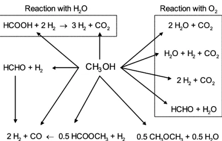
3.1.1 Reaction pathways for methanol conversion
Fig. 3.1 shows possible reaction pathways for catalytic conversion of methanol in the presence of O2 and steam. It should be remembered that the reaction route for H2
formation can be quite complex, as several different reactions involving methanol may occur, simultaneously or consecutively, on the catalyst surface in the presence of O2
and/or steam. For instance, water-gas shift and combustion reactions may occur in addition to the desired hydrogen-producing reactions. Fundamental understanding of methanol reforming requires knowledge of all processes involved.
3.1.2 Decomposition of methanol
Methanol decomposition is the reverse of methanol synthesis from H2 and CO. The
reaction has been thoroughly investigated over a wide variety of catalytic materials, such as copper [30-37], nickel [38-39] and precious metals [40-43]. The equation is given below: CH3OH (l) → CO + 2 H2 ∆H0 = 128 kJ/mol (3.1) 2 H2O + CO2 HCOOH + 2 H2 → 3 H2+ CO2 HCHO + H2O 0.5 CH3OCH3+ 0.5 H2O 2 H2+ CO ← 0.5 HCOOCH3+ H2 HCHO + H2 2 H2+ CO2 H2O + H2+ CO2 CH3OH
Reaction with H2O Reaction with O2
2 H2O + CO2 HCOOH + 2 H2 → 3 H2+ CO2 HCHO + H2O 0.5 CH3OCH3+ 0.5 H2O 2 H2+ CO ← 0.5 HCOOCH3+ H2 HCHO + H2 2 H2+ CO2 H2O + H2+ CO2 CH3OH
Reaction with H2O Reaction with O2
The reaction is highly endothermic and, as such, well suited for example in the recovery of waste heat or to increase the heating value of fuel methanol, for instance in ICEs. However, the reaction is less suitable for supplying H2 to fuel cells, which are poisoned by
CO, a primary product in this case. Therefore, the process itself will not be discussed in further detail in this thesis.
3.1.3 Steam reforming of methanol
The steam reforming of methanol is a well-documented reaction with high efficiency, as H2 is formed from both methanol and water. The equation is given below:
CH3OH (l) + H2O (l) → CO2 + 3 H2 ∆H0 = 131 kJ/mol (3.2)
The reaction can be carried out over copper-based catalysts in the 200-300 °C range with high selectivities to both H2 and CO2 [44-64]. The H2 concentration can reach up to 70-75
vol.% (on a dry basis) under favourable conditions. Precious metals, such as palladium, have also received some attention as catalysts for the reaction [65-67].
Due to the endothermic nature of the reaction, heat needs to be supplied from an external source. In an FCV, this can be accomplished by combustion of residual H2 from the fuel
cell’s anode chamber, a fraction of the fuel methanol or some other fuel. This, as well as the need to produce steam, decreases the efficiency of the process. However, a high overall system efficiency can be obtained in an FCV equipped with a steam reformer.
3.1.4 Partial oxidation of methanol
Partial oxidation of methanol offers some advantages when compared to the steam-reforming reaction. The reaction route is exothermic, i.e. thermodynamically favoured, and uses air or O2 instead of steam as oxidant:
CH3OH (l) + 0.5 O2 → CO2 + 2 H2 ∆H0 = -155 kJ/mol (3.3)
The overall thermal efficiency of a partial oxidation system is somewhat compromised by its exothermic nature. However, there is no need for external heat exchange and due to the high reaction rate, a partial oxidation reformer can be made compact, lightweight and dynamically responsive.
Cu/ZnO-based catalysts exhibit high activity for partial oxidation in the 200-300 °C range [68-70] and palladium-based catalysts have also received some attention [71,72]. Under favourable conditions, partial oxidation with O2 yields H2 and CO2 in a 2:1 ratio. If air is
used as oxidant, the reformed gas will also contain about 40 % N2. It should be noted that
dilution of the reformate increases the size of the fuel cell due to the larger flow channels required in the field plates. It also lowers the power density of the fuel cell due to the lower H2 concentration in the anode gas.
The presence of O2 also complicates the process. Due to the exothermicity, thermal
catalyst bed. The loss of H2 and/or methanol by direct oxidation may also be considerable
if appropriate reaction conditions are not maintained, resulting in a poor selectivity for H2. 3.1.5 Combined reforming of methanol
Steam reforming of methanol with addition of O2, referred to as combined reforming or
oxidative steam reforming, was proposed in the mid 1980s by Huang and co-workers [73,74] as a new route for production of H2 from methanol over copper catalysts. In recent
years, the number of publications on this topic has increased rapidly [75-85].
This process alternative appears attractive, being a combination of steam reforming and partial oxidation and combining the best features of both reactions. The general equation is given below, where 0 ≤ a ≤ 0.5:
CH3OH + (1 - 2a) H2O + a O2 → CO2 + (3 - 2a) H2 (3.4)
By varying the parameter a, the thermal nature of the reaction can be varied from exothermic to endothermic and the overall reaction can be chosen such that the reaction can respond to the system’s requirements at any given moment. The process is preferably maintained thermally neutral or moderately exothermic and is at times referred to as autothermal reforming when operated under close to adiabatic conditions. The equation for close to autothermal operation is given in Eq. (3.5):
CH3OH (l) + 0.6 H2O (l) + 0.2 O2 → CO2 + 2.6 H2 ∆H0 = 16.6 kJ/mol (3.5)
Experience has shown that maintaining H2O/CH3OH and O2/CH3OH molar ratios of 1.3
and 0.2, respectively, gives optimum performance, i.e. high H2 generation capacity and
minimum CO levels. This implies that all O2 is converted while steam is maintained in
excess.
The reaction route has some further advantages over conventional steam reforming, in addition to its thermal neutrality. Under appropriate conditions, CO production is minimal, while H2 selectivities are comparable to those obtained during steam reforming.
3.2 The fuel-processing system
The optimal design of the fuel-processing system for a PEM fuel cell vehicle remains an open question. No doubt, there are many opportunities for innovative catalyst, reactor and process design. FCVs require compact and low-cost solutions, which are suitable for mass production and enable reliable operation with minimum maintenance, as dictated by the automotive sector and its demanding customers.
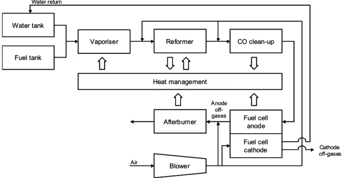
The basic components of a methanol-reforming system for an FCV are shown in Fig. 3.2. The system contains fuel and water tanks, from which a methanol-water mixture is pumped through a vaporiser into the reformer. After passing through a clean-up stage removing CO (see further in Section 3.4), the reformate containing mainly H2, CO2 and
blower/compressor to the cathode where water vapour is produced and subsequently condensed and re-routed to the water tank.
It should be noted that the anode effluent, the so-called anode off-gases, must flow through the cell unlike the case for direct hydrogen-fuelled systems. Hence, the anode effluent will contain a considerable amount of unconverted H2. This constitutes energy
that can be utilised and also poses environmental concerns, which is why the anode off-gases are combusted in the afterburner. Possibly, the exhaust off-gases can then pass through a turbine, in which some of the remaining energy is utilised for compression of the air needed in the system.
The fuel processor also needs to incorporate a heat management system to control the temperature of the vaporiser, reformer and fuel cell, as well as a humidifier for the gas entering the cathode compartment. The fuel processor becomes complete with monitoring and control systems.
An obvious advantage of the fuel cell engine, in addition to those mentioned in Chapter 2, is its modular design. The various subcomponents of the system can easily be fitted below the passenger compartment of the vehicle, as in NECAR 3, 4 and 5 from DaimlerChrysler, which are based on the Mercedes A-Class minivan.
3.3 Reactor solutions
Depending on the type of process for methanol reforming onboard the vehicle, different reactor solutions are needed. Exothermic and endothermic reactors require completely different designs. Efficient heat exchange is a crucial point, especially for fuel-processing systems based on methanol steam reforming.
Fuel tank Water tank
Vaporiser Reformer CO clean-up
Heat management Afterburner Blower Air Anode off-gases Water return Fuel cell anode Fuel cell cathode Cathode off-gases Fuel tank Water tank
Vaporiser Reformer CO clean-up
Heat management Afterburner Blower Air Anode off-gases Water return Fuel cell anode Fuel cell cathode Cathode off-gases
Two in principle different approaches have evolved to cope with the heat transfer task in steam-reforming reactors. The reactor may be configured as a plate-type heat exchanger with counter-current flow in parallel channels. Combustion of methanol and/or residual H2
in the anode off-gases in one channel thus provides the energy needed for steam reforming in the next. There are several examples of this solution in the literature (see e.g. a paper by de Wild and Verhaak [62]).
The other alternative involves adding O2 or air directly to the methanol-water feed
mixture, thereby enabling direct heating of the reaction. For instance, the HotSpotTM fuel
processor developed by Johnson Matthey is based on this principle [86,87]. This process corresponds to the one referred to as combined reforming in this thesis and enables operation under close to autothermal conditions. However, it requires careful catalyst handling in order to avoid thermal deactivation of the catalyst. Multi-staged catalytic solutions may be advantageous in this case, as discussed in Paper VI.
An exothermic partial oxidation reformer, on the other hand, does not need heating. Instead, the system requires efficient cooling in order to avoid over-oxidation and deactivation of the catalyst bed. The catalytic results presented in Chapter 5 show that there will be considerable temperature variations along the catalyst bed during partial oxidation with O2. If a packed-bed reactor (PBR) configuration is chosen, this will pose
strict demands on temperature control in order to avoid thermal runaway and hot spot formation. Therefore, other reactor solutions may be more appropriate for exothermal operation.
Overall thermal optimisation of the system is another important topic. The overall system efficiency must be acceptable, requiring efficient heat management. Clearly, endothermic reactor solutions contribute to an improved overall efficiency, while partial oxidation systems suffer from quite substantial heat losses. The fuel processor may further be pressurised or operate at atmospheric pressure, depending on the process for methanol conversion. A low pressure favours all reforming reactions thermodynamically, while catalytic kinetics and reactor sizing benefit from operation at an elevated pressure.
3.4 CO clean-up (Paper I)
When the H2 feedstock for the PEM fuel cell is obtained by reforming of methanol, the
formation of a small amount of CO is inevitable, irrespective of methanol conversion process. The content of CO is typically in the range from a few parts per million to 1.0 vol.%. The reformate will also contain unconverted methanol, CO2, steam and possibly
small amounts of other by-products. CO in levels exceeding a few parts per million poisons the PEM fuel cell by blocking the active sites of the platinum-based anode electrocatalyst, thus hampering the fuel cell performance. Therefore, CO removal is paramount for successful operation of the fuel cell.
The choice of clean-up technology affects both the design and the overall efficiency of the fuel cell system. The operating temperature of the clean-up step should ideally lie between the outlet temperature of the reformer (200-300 °C) and the inlet temperature of the PEM fuel cell (~ 100 °C). The size of the clean-up step is also determined by the performance
of the methanol reformer. Efficient suppression of CO formation in the reforming reactor reduces or completely eliminates the need for after-treatment. This is related to operating conditions and the choice of catalytic material, as will be shown in Chapter 5 of the thesis. Depending on the amount of CO that needs to be removed, different strategies may be chosen. Possible technologies for CO abatement include selective oxidation, reduction (methanation), adsorption or the use of palladium membranes. As adsorption typically requires a volume of adsorbent that is unacceptable for automotive applications, this technology will not be discussed in further detail. The other processes are briefly described below.
3.4.1 Equilibrium CO content and water-gas shift
The CO content in the reformate is regulated by the water-gas shift (WGS) reaction, converting CO and water to CO2 and H2:
CO + H2O → CO2 + H2 (3.6)
Being exothermic, high temperatures suppress the reaction. Hence, CO levels above equilibrium can be decreased in a low-temperature WGS reactor. The reaction is catalysed in the low (180-250 °C) to mid-temperature range (220-350 °C) by copper-based catalysts [88-93]. The process not only reduces the amount of CO, but also increases the yield of H2. However, the additional amount of energy required for vaporisation of the water
needed to drive the equilibrium towards low CO levels clearly constitutes a disadvantage. WGS may constitute a first clean-up step when the CO content is high, followed by secondary CO removal to reach ppm levels. However, it is rather unlikely that the CO content in the reformate from a correctly operated methanol reformer will exceed that predicted by equilibrium. Instead, this implies that increasing residence time in the reactor will increase the level of CO as copper-containing reforming catalysts also catalyse the reverse water-gas shift (RWGS) reaction. Other technologies are needed for CO levels below equilibrium.
3.4.2 Selective CO oxidation
Selective CO oxidation, sometimes referred to as preferential oxidation, involves the oxidation of CO with O2 or air [94-98]:
CO + 0.5 O2 → CO2 (3.7)
The technological challenge lies in the oxidation of CO in presence of excess H2, without
loss of H2 through direct oxidation. Due to the exothermicity of both CO and H2 oxidation
reactions, it is essential to remove heat from the reactor in order to control the activity and selectivity of the process. Major efforts have been focused on alumina-supported platinum catalysts.
3.4.3 Methanation
By methanation, CO is converted into methane by reaction with H2 [99-101]:
CO + 3 H2 → CH4 + H2O (3.8)
This process is not suitable for removal of large amounts of CO. As each converted molecule of CO consumes three H2 molecules, the system suffers a substantial H2 loss. In
addition, the presence of CO2 may severely compromise the process by consuming large
amounts of H2:
CO2 + 4 H2 → CH4 + 2 H2O (3.9)
3.4.4 Palladium membranes
Dense palladium and palladium-silver alloy membranes exhibit infinite permselectivity for H2. As such, they can be used for the production of ultra-pure H2 for PEM fuel cells
[102-105]. The most common configuration consists of a few nanometres of palladium film on a porous tubular substrate. A difference in H2 partial pressure between the feed
and the permeate provides the driving force for separation. The pressure difference is generally achieved by operating the upstream side of the membrane at high pressure and/or by using a sweep gas on the permeate side. The main disadvantages are related to high material costs and a high operating pressure, typically in the 20 bar region.
The possibility to combine reforming catalyst and separator in a membrane reactor to carry out simultaneous reaction and separation appears attractive. However, this option requires strict compatibility between catalyst and membrane with respect to operating conditions.
4 Catalysts
The use of a catalyst for onboard methanol reforming in a fuel cell vehicle implies a number of criteria that the material must fulfil. These include sufficient activity at relatively low temperature (< 250 °C), low manufacturing cost, the possibility for mass production, a high resistance to sintering and poisoning, and the ability to withstand thermal and mechanical shock.
Due to the high exothermicity of partial and total methanol oxidation reactions, the need for thermal resistance is especially important. The catalyst must also be able to withstand repeated start-up and shutdown with associated redox cycles. This criterion turns out to be paramount, as will be shown in the present and the following chapter of the thesis.
In the following discussion, the preparation and characterisation of copper and palladium-based catalysts is described. Details regarding experimental parameters are found in Papers II-VII. Catalytic results are reported in the following chapter.
4.1 Catalyst development scope
The process of developing a catalytic system for a given application consists of several steps. The composition of the active phase and promoters must be optimised. A suitable surface state and appropriate pre-treatment conditions must be found. The morphology of the material including structural parameters such as particle size, dispersion and stability must also be investigated. As catalytic behaviour is closely related to all of these parameters, changing just one may affect the overall performance of the catalyst.
Two main groups of materials for methanol conversion can be identified – those based on copper and those based on palladium. Their properties and catalytic behaviour in methanol conversion reactions differ quite markedly. Copper-based catalysts are traditionally used for reactions involving methanol synthesis and conversion. Particularly Cu/ZnO-based formulations incorporating various additives, such as Al2O3 and ZrO2,
have received considerable attention. In parallel, noble metal catalysts are receiving increasing interest for methanol synthesis and conversion reactions.
In this chapter of the thesis, the importance of the choice of preparation method is discussed. In this context, the microemulsion technique is described as a tool to design catalysts with specific properties, e.g. narrow particle size distribution, controlled surface area and well-mixed constituents. The influence of additive incorporation into Cu/ZnO catalysts is also evaluated, as well as the effect of palladium particle size on activity and selectivity for methanol conversion.
4.2 Catalyst preparation
The functionality of a catalyst in a certain reaction is strongly affected by the method of preparation. Surface structure and composition, dispersion of the active phase, crystallinity, interfacial properties and possible synergies in the material are all properties that are influenced by the preparation route. These parameters, in turn, affect catalyst performance in terms of both stability and reactivity. It is clear that a suitable catalyst preparation route is needed in order to reach the desired properties.
Conventional methods for catalyst preparation include precipitation, for the fabrication of metal oxides and mixtures thereof, and impregnation for deposition of an active metal onto a high surface-area support [106]. Less common methods include sol-gel technique, grafting, milling and chemical vapour deposition (CVD).
Bridging the pressure gap is an expression used to describe the need to link vacuum
studies of model catalyst surfaces (single crystals) using in-situ techniques with so-called high pressure systems (≥ 1 bar) under real conditions, but with limited control of catalyst surface structure. Most conventional preparation techniques suffer from the difficulty, not to say impossibility, to control surface area, particle size and distribution of the active phase. The particle size distribution is governed mainly by the structure of the support. Hence, the introduction of new methods, such as the microemulsion technique, is needed.
4.2.1 Microemulsion technique
There are several advantages associated with using microemulsions for catalyst preparation. The microemulsion technique produces catalysts with very specific properties in terms of both particle size and homogeneity. The particles can be kept in the nanometre or even Angstrom size range with extremely narrow size distributions [107-109]. In the case of metallic particles, the metal load in the catalyst can be varied without affecting the particle size. In the case of metal oxides, adjusting the composition of the microemulsion can control the surface area of the material, which is governed by the size of the precursor particles. Additionally, the calcination temperature required for crystallisation can be kept
low due to the small particle size and homogeneity of the precursor, thus reducing the risk for loss of activity due to sintering.
4.2.1.1 Microemulsions
According to the accepted definition, a microemulsion is a system of water, oil and surfactant that forms an optically isotropic solution [110]. Although it is heterogeneous at the molecular level, it is thermodynamically stable and forms spontaneously. Microemulsions can be of the water-in-oil (w/o) or oil-in-water (o/w) type. In the former, the so-called reversed micelles are in the Angstrom or nanometre size range.
The surfactant molecules reside at the water-oil interface, the hydrophilic heads in the water phase and the hydrophobic tails in the oil phase. As the concentration of surfactant increases, the interface becomes saturated with surfactant molecules and colloidal spherical aggregates form in the solution. In this way, the interfacial tension is drastically reduced, leading to a substantial increase of the interfacial area.
The size of the reversed micelles is determined not only by the composition of the microemulsion, but also by the nature of the surfactant and the hydrocarbon. The water droplet size increases with the molar water/surfactant ratio (w0), commonly used to
express the composition of a microemulsion. The considerable curvature of the micelles implies that not only the hydrophile-hydrophobe balance, but also the molecular geometry of the surfactant molecule is an important factor, which governs the size of the droplets. Furthermore, metal salts dissolved in the water phase may affect the droplet size due to interactions with the hydrophilic head groups of surfactant molecules.
Although microemulsions are thermodynamically stable, they are extremely dynamic systems. Water droplets collide, form transient dimers, exchange their water content and break down. These processes take place on a millisecond time scale, rendering it possible for chemical reactions to occur in the water domain.
4.2.1.2 Catalyst preparation in microemulsion
The microemulsion technique was developed in the early 1980s by Boutonnet et al. [111]. Common wet chemical procedures, such as precipitation or reduction of salts, may be carried out inside the microemulsion droplets, which function as small reaction vessels. Particles formed in this way are limited in their growth by the surfactant molecules, making it possible to produce nanosized particles with a very narrow size distribution. In recent years, the microemulsion technique has been used for preparation of a variety of materials, ranging from metallic particles to metal oxides, semiconductors and magnetic materials [111-115].
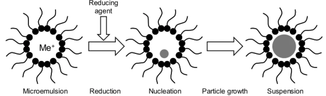
In short, the metal precursor is dissolved in the water phase of the microemulsion and particles are formed by adding a reducing or precipitating agent, which initiates nucleation (cf. Fig. 4.1). In the first intramicellar step, very small nuclei are formed. Because of the fast kinetics of these reactions, a high number of nuclei are formed. The rapid consumption of the precipitating agent in the nucleation process depresses further particle growth and contributes to the monodispersity of the particles. In the second intermicellar
step, the particles grow due to reactions between droplets with exchange of water phase. The particles generally form a stable and isotropic suspension of the elemental metal or oxide precursor. Hence, the microemulsion can be used as both preparation and deposition medium for catalyst preparation. A support can be impregnated by chemical or thermal destabilisation of the suspension, or the particles can be recovered for further processing (see Papers II, III and V for further experimental details).
4.3 Copper-based catalysts
Copper-based catalysts are used in numerous chemical processes of industrial importance. For instance, the well-known Cu/ZnO/Al2O3 catalyst is used both in the low-pressure
methanol synthesis process developed by ICI [116] and in the low-temperature water-gas shift reaction [88]. There is still some controversy regarding the respective roles of copper and ZnO in the catalyst. The debate concerning the exact nature of Cu-ZnO interactions, the existence of a synergistic effect, the active site and the chemical state of copper in the catalyst is lively.
Different theories exist to describe the nature of Cu-ZnO interactions in the catalyst [117]. For instance, some authors suggest that copper is incorporated in the ZnO phase on interstitial and substitutional sites, assuming three possible valence states (Cu0, Cu+ and
Cu2+) [118]. Others speculate that the hydrogenation of formate adsorbed on Cu0 proceeds
via hydrogen spillover from ZnO, acting as a reservoir of atomic hydrogen [119,120].
Some have proposed the formation of surface CuZn alloy upon migration of ZnO onto Cu0 crystallites [121,122]. Finally, it has been claimed that there is no synergistic effect, i.e. that Cu0 provides the catalytic activity, while ZnO acts by stabilising the copper
surface area [123].
Various methods for preparation of Cu/ZnO-based catalysts are described in the literature. These include wet chemical processes, such as impregnation [124] and co-precipitation in aqueous solution [57,59,68,69,125-129] or other solvents [130-134], as well as mechanical processes, such as milling [135]. Different precipitating agents have been employed for the common precipitation route, e.g. sodium carbonate [57,59,68,69,125-128], sodium aluminate [129] and oxalic acid [130-134]. Furthermore, the influence of preparation parameters, such as the addition rate of the precipitating agent, temperature, pH [57,126,127] and the effect of calcination and reduction conditions [128,133] has been thoroughly investigated. Addition of Al2O3 to the binary catalyst improves the copper
dispersion and increases catalyst stability. The copper/zinc molar ratio is generally maintained between 1:2 and 2:1 and Al2O3 comprises up to about 15 wt.% of the material.
In the work presented in this thesis, a series of Cu/ZnO-based catalysts were prepared by both conventional co-precipitation and microemulsion technique. The following discussion is based on the materials listed in Table 4.1.
Nucleation Me+ Reduction Suspension Microemulsion Reducing agent Particle growth
Figure 4.1. The procedure for nanoparticle preparation by microemulsion technique.
4.3.1 Binary Cu/ZnO catalysts prepared in microemulsion (Papers II and III)
In Papers II and III, the preparation of a series of Cu/ZnO catalysts containing 20-70 wt.% copper (as metal) by the microemulsion technique is described (Table 4.1). All catalysts were prepared in the same way, i.e. by mixing a microemulsion containing copper and zinc nitrates in the water phase with another containing oxalic acid, the precipitating agent. The surfactant system consisted of nonylphenolethoxylate (NP-5), 20 wt.% in cyclohexane. The catalysts differ only in copper/zinc ratio and the water content of the microemulsion, which determines the size of the water droplets and hence, the size of the precipitated oxalate precursors.
A Cu/ZnO catalyst derived from hydroxycarbonates prepared in aqueous solution (CZ:CP-60) is used as reference catalyst in this part of the work (termed conventional or
reference).
4.3.1.1 Catalyst morphology
The BET surface areas of the microemulsion catalysts of the M/10 type (see Table 4.1) measured by N2 adsorption-desorption range from 22 to 36 m2/g. There is no substantial
variation with chemical composition, but the surface area reaches a maximum value for the catalyst composed of equal amounts of copper and zinc. By decreasing the water content of the microemulsion (i.e. the droplet size) from 10 to 5 wt.%, the surface area of the catalyst increases significantly, reaching 87 m2/g for catalyst CZ:M/05-87. This is
expected, as small water droplets produce fine precursor particles and consequently a high surface area after calcination. The surface areas of the catalysts derived from hydroxycarbonates prepared in aqueous solution are in the 50-60 m2/g range, which is comparable to values reported in the literature (see e.g. the paper by Alejo et al. [68]). N2O chemisorption was used to determine the Cu0 surface area and to calculate the copper
dispersion in some of the catalysts. The method used, reactive frontal chromatography, is similar to the one described by Chinchen et al. [136]. The copper surface areas of catalysts CZ:M/10-34 and CZ:M/10-36 are similar, 7.2 and 8.8 m2/g, respectively.
Compared to these two catalysts and considering its much lower copper content, catalyst CZ:M/05-87 possesses a relatively high Cu0 surface area (6.6 m2/g). This is clearly
illustrated by calculating the copper dispersions, relating the amount of surface copper to the total amount of copper in the sample, assuming a value of 1.46×10¹⁹ copper atoms/m2
found to be 5.7 %, substantially higher than in the other two microemulsion catalysts, exhibiting values of around 3.5 %. The reference CZ:CP-60 catalyst has a significantly higher Cu0 surface area of 21.5 m2/g, corresponding to a dispersion of 10.3 %. A
comparison with values reported in the literature is difficult, considering the many different methods and reaction conditions used [138].
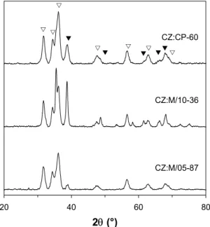
The particle size of catalysts CZ:CP-60 and CZ:M/10-34 was estimated by transmission electron microscopy (TEM). The micrographs reveal that the conventional catalyst consists of small ZnO crystallites approximately 10 nm in diameter, while no CuO crystallites are visible, indicating a high copper dispersion with particles smaller than about 4 nm. In the microemulsion material, on the other hand, large CuO crystallites (20-40 nm) can be observed and ZnO crystallites of approximately 20 nm are predominant. Powder X-ray diffraction (XRD) was used to determine the crystalline structure of the catalysts after calcination. Typical X-ray diffraction patterns for three of the calcined samples are shown in Fig. 4.2. The measurements show that the metal oxides are obtained after calcination, as peaks indicative of crystalline CuO and ZnO can be identified in all cases. Line-broadening confirms that the CuO crystallites are smaller in CZ:M/05-87 than in CZ:M/10-36. Catalyst CZ:CP-60 also appears to contain small CuO particles, which is consistent with the results presented above.
4.3.1.2 Copper distribution
The ratio RCu shown in Eq. (4.1) is a convenient way of estimating the distribution of
copper and zinc in the material. This parameter relates the copper surface area of the reduced catalyst to the BET value of the calcined precursor. A better approach would involve a determination of the BET area of the reduced material. However, the possible surface re-oxidation induced by sample handling makes the relation described by Eq. (4.1) a useful estimation for binary Cu/ZnO catalysts.
20 40 60 80 2θ (°) CZ:CP-60 CZ:M/10-36 CZ:M/05-87 V T V V V V V V T T TT
Figure 4.2. X-ray diffraction patterns of calcined
copper-zinc catalysts prepared in microemulsion and aqueous solution. (V) ZnO; (T) CuO.
area surface BET content copper area surface Cu RCu × = 0 (4.1)
It is important to note that the surface area of pure ZnO is quite similar to that of CuO. For instance, ZnO prepared in microemulsion (M/10) had a surface area of 46 m2/g. However,
in ternary and quaternary materials incorporating high surface-area additives (Al2O3
and/or ZrO2), the surface area of the structural stabiliser is considerably higher, the RCu
approximation then becoming less useful.
Some interesting conclusions can be drawn when the RCu values in Table 4.1 are
compared. The ratio is close to unity for the reference catalyst (CZ:CP-60), while the corresponding values for catalysts CZ:M/10-34 and CZ:M/10-36 are about 0.5. Catalyst CZ:M/05-87 exhibits the lowest value (0.34). These results suggest that the copper and zinc phases in the hydroxycarbonate-derived material are present in what resembles a physical mixture of the two metal oxides. The lower values for the microemulsion catalysts imply that copper is partially embedded in the ZnO phase, providing less exposed copper surface, but a greater Cu-ZnO interfacial area.
4.3.2 Cu/ZnO catalysts promoted by Al2O3 and ZrO2 (Paper VII)
While the incorporation of Al2O3 in Cu/ZnO catalysts is well-documented, recent studies
have shown that inclusion of ZrO2 provides improved properties with respect to catalytic
activity, selectivity and stability [37,59,75,76,81,139,140]. For instance, Fisher and Bell [37,139,140] studied the reaction mechanism for methanol synthesis and decomposition over Cu/ZrO2 catalysts and suggest that a synergy exists between copper and ZrO2. All the
major reaction intermediates are found on ZrO2, while copper dissociates molecular
hydrogen, which is provided to copper by a spillover mechanism.
In Paper VII, the preparation of Cu/ZnO catalysts containing Al2O3 and ZrO2 additives by
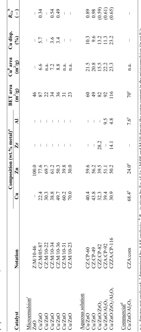
decomposition of hydroxycarbonate precursors formed in aqueous solution is described. The catalysts differ slightly with respect to copper/zinc ratio, but mostly in the make-up of the additives. The following discussion focuses on catalysts CZ:CP-49, CZZ:CP-82, CZA:CP-92 and CZZA:CP-116 (Table 4.1).
4.3.2.1 Catalyst morphology
It is evident that addition of either ZrO2 or Al2O3 to the catalyst greatly increases the
surface area, reflected by the BET surface areas in Table 4.1. A combination of the two is known to constitute the most favourable option and clearly, the quaternary catalyst displays the highest surface area of all. Results presented in the literature demonstrate that substitution of part of the aluminium by zirconium greatly improves both copper dispersion and reducibility [76,81]. Nevertheless, care should be taken when the values are compared, as the catalysts contain different amounts of additives.
By incorporating Al2O3 or ZrO2 into the catalyst, both high surface-area metal oxides, a
large surface is provided onto which copper can be effectively distributed. Measurements of the catalysts’ Cu0 surface areas by N
2O chemisorption provided results ranging from
(Table 4.1). As the catalysts contain different amounts of copper, the copper dispersions give a more accurate picture. The dispersions range from 9.6 to 23.2 %, the quaternary material again displaying the highest value. The Cu/ZnO catalyst exhibits the lowest value, as expected in absence of a structural stabiliser.
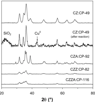
Fig. 4.3 shows X-ray diffractograms of the four catalysts, including that of the binary catalyst after exposure to partial oxidation reaction conditions. Peaks indicative of crystalline CuO and ZnO phases can be identified, while signals characteristic of crystalline zirconium and aluminium oxide phases are absent. There are two possible explanations for this. Either zirconium and aluminium occur in highly disordered or amorphous states due to the relatively low calcination temperature (350 °C), or the crystallite size is simply too small to be detected due to line-broadening. In catalysts Cu/ZnO/ZrO2 andCu/ZnO/ZrO2/Al2O3, no CuO lines are visible, indicating that copper is
highly dispersed, in agreement with the N2O chemisorption experiments. Catalyst
Cu/ZnO/Al2O3, on the other hand, contains large copper crystallites as evidenced by the
high intensities of the characteristic CuO lines. After exposure of the Cu/ZnO catalyst to reaction conditions, the features associated with CuO disappear at the expense of the characteristic Cu0 line appearing at 2θ ∼ 43°.
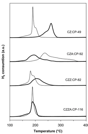
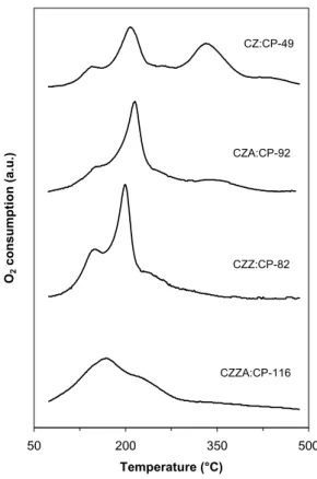
4.3.3 Catalyst stability and redox properties (Papers III and VII)
In a fuel cell vehicle, the catalyst will be subjected to repeated reduction and oxidation during start-up and shutdown and during variations in operating conditions. Therefore, it is important to understand how the materials are affected by redox cycles. The catalysts were subjected to successive temperatuprogrammed reduction, oxidation and re-reduction in order to study the reducibility of copper and the catalysts’ ability to withstand cycled reduction-oxidation without deterioration. This treatment can be considered as accelerated ageing as it simulates conditions, which may be experienced in the fuel cell reformer. 20 40 60 80 2θ (°) CZ:CP-49 CZA:CP-92 CZZ:CP-82 CZZA:CP-116 CZ:CP-49 (after reaction) Cu0 SiO2
Figure 4.3. X-ray diffraction patterns of copper-zinc
catalysts prepared in aqueous solution, incorporating zirconium and/or aluminium additives.
Table 4.1.
Summary
of copper-based cataly
sts and their phy
sic
ochem
ical pr
ope
rties (the cataly
sts are nam ed according t o their com position , method of
preparation and surface ar
ea). Composition (wt.% metal ) a BET area Cu 0 area Cu disp. RCu b Catalyst Notation Cu Zn Zr Al (m 2 /g) (m 2 /g) (%) ( – ) Microem ulsion c ZnO Z:M/10-46 – 100. 0 – – 46 – – – Cu/ZnO CZ:M/05-87 22.4 77. 6 – – 87 6.6 5.7 0.34 Cu/ZnO CZ:M/10-22 30.3 69. 7 – – 22 n.a. – – Cu/ZnO CZ:M/10-34 38.8 61. 2 – – 34 7.2 3.6 0.54 Cu/ZnO CZ:M/10-36 49.7 50. 3 – – 36 8.8 3.4 0.49 Cu/ZnO CZ:M/10-31 60.2 39. 8 – – 31 n.a. – – Cu/ZnO CZ:M/10-23 70.0 30. 0 – – 23 n.a. – – Aqueous solu tion Cu/ZnO CZ:CP-60 40.4 59. 6 – – 60 21.5 10.3 0.89 Cu/ZnO CZ:CP-49 43.8 56. 2 – – 49 20.8 9.6 0.98 Cu/ZnO/ZrO 2 CZZ:CP-82 32.3 39. 5 28.2 – 82 15.5 13.2 (0.59) Cu/ZnO/Al 2 O3 CZA:CP-92 39.4 51. 1 – 9.5 92 22.2 11.3 (0.61) Cu/ZnO/ZrO 2 /Al 2 O3 CZZA:CP-116 30.9 50. 2 14.1 4.8 116 23.3 23.2 (0.65) Co mmercial d Cu/ZnO/Al 2 O3 CZA:co m 68.4 e 24. 0 e – 7.6 e 70 e n.a. – – n.a. de notes not analysed; a determin ed b y AAS an alysis; b R Cu is gi ve n by E q. (4 .1 ); c M/0 5 and M/10 d eno te th e water con ten t i n th e m icro em ulsio n (in wt.%); Sü d-C hem ie G-66 M R ; e re po rt ed by m anufact ure r
![Table 2.1. Fuel cell categorisation [9,10].](https://thumb-eu.123doks.com/thumbv2/5dokorg/4954140.136235/14.892.104.777.799.1103/table-fuel-cell-categorisation.webp)