www.vti.se/publications
Sigurdur Erlingsson Håkan Carlsson
The Svappavaara Road Test Sections
Instrumentation
VTI notat 12A–2014 Published 2014
Preface
This VTI note describes briefly the construction and instrumentation of four new test road structures that have been built on E45 in Norrbotten County in northern Sweden close to the Svappavaara municipality. Each test road structure is 100 metres long. Both road response, performance sensors and climate sensors are included on each structure. The Swedish Transport Administration has financed the project and their contact persons have been Johan Ullberg and Marcus Larsson.
Warm thanks is conveyed to all who participated and made this possible, the contractor Lemminkäinen that built the structures, The Swedish Transport Administration and involved colleagues at VTI.
Linköping, February 2014
Quality review
A review seminar was carried out on 10 January 2014 where Björn Kalman reviewed and commented on the report. Sigurdur Erlingsson has made alterations to the final manuscript of the report. The research director of the project Dr Björn Kalman approved the report for publication on 31 January 2014. The conclusions and recommendations expressed are the author’s/authors’ and do not necessarily reflect VTI’s opinion as an authority.
Kvalitetsgranskning
Granskningsseminarium genomfört 30 januari 2014 där Björn Kalman var lektör. Sigurdur Erlingsson har genomfört justeringar av slutligt rapportmanus. Projektledarens närmaste chef Dr. Björn Kalman har därefter granskat och godkänt publikationen för publicering 31 januari 2014. De slutsatser och rekommendationer som uttrycks är författarens/författarnas egna och speglar inte nödvändigtvis myndigheten VTI:s uppfattning.
Innehållsförteckning
Summary ... 5
Sammanfattning ... 7
1 Introduction ... 9
2 Location ... 10
3 The heavy vehicle characteristics ... 11
4 The test sections ... 12
5 Instrumentation and data acquisition system ... 15
6 Conclusions ... 22
References ... 23 Appendix A: The location of the road sensors within the 16 m long stretch, for all the four test roads.
The Svappavaara road test sections – Instrumentation
by Sigurdur Erlingsson and Håkan Carlsson
The Swedish National Road and Transport Research Institute (VTI) SE-581 95 Linköping
Summary
This report describes four new instrumented test road sections that have been built on E45 close to the Svappavaara in Norrbotten County in Northern Sweden. The structures are located about 100 km north of the Arctic Circle in a climate that is characterized by long cold winters and short mild summers.
Norrbotten County is a sparsely populated area where the pavement structures consist of thin pavements with relatively low traffic volume. A new ore deposit, the Kaunisvaara project, was opened in 2012, meaning that the ore will be transported along the existing road network about 160 kilometers to where it will be transferred to a railway. The ore operator has received a permit to use 90 ton vehicles instead of the permissible 60 tons, consisting of a single wheel steering axle and triple dual wheel tridem axles to transport the iron ore. When the ore processing will be in full operation around 66.000 journeys per year will pass over the network, or on average about 7–8 passes per hour with about seven and a half minutes between the passes. Due to this new ore transport it will be necessary to strengthen the local road network. As part of the process to evaluate the performance of a suitable pavement structure these four instrumented test road structures have been selected and built.
The structures are instrumented with road performance and climate sensors. The
structures will be monitored over the years to come, though the details of the monitoring programme have not yet been decided.
Each test section is around 200 metres long, consisting of a 100 metres long inner part that constitutes the intrinsic test section. The structures were built and instrumented in the summer of 2012 except for the wearing course that was placed in the summer of 2013 along with the temperature sensors that are placed in the asphalt layers.
The instrumentation in each section consists of Emu coils for vertical strain
measurement devices, soil pressure cells for vertical stress measurements and tensile strain gauges located at the bottom of the bound road base layer. In addition there are moisture rods located in three of the structures and a temperature (frost) rod located in structure 3. A weather station (2527 Svappavaara) operated by the Transport
Administration is located 3.2 kilometre south-east of the test site. The project is sponsored by the Swedish Transport Administration.
Nya testvägsträckor på E45 vid Svappavaara – Instrumentering
av Sigurdur Erlingsson och Håkan Carlsson VTI, Statens väg- och transportforskningsinstitut 581 95 Linköping
Sammanfattning
Denna rapport beskriver fyra nya instrumenterade vägsträckor på E45 nära samhället Svappavaara i Norrbottens län.
I samband med att en ny malmgruvstäkt öppnades i Kaunisvaara 2012 kommer all malm som utvinns där att transporteras på det befintliga vägnätet längs Rv99, Rv395, E45 och E10 till Pitkäjärvi, totalt 160 kilometer. Malmen kommer därefter att omlastas till järnväg och transporteras till Narvik för vidare transport sjövägen. Malmbryts-operatören har erhållit ett tillstånd att använda forden med den totala vikten 90 ton i stället för den 60 ton maximala tyngd som tillåts på vägnätet. Fordonen består av en 9 ton tung styraxel med singelhjul samt tre trippelaxlar där varje trippelkonfiguration väger 27 ton. När malmtäkten kommer att vara i full drift beräknas det bli omkring 66 000 överfarter av dessa fordon per år på vägsträckan. Detta motsvarar omkring 7–8 överfarter per timme eller 7½ minut mellan passagerna.
Detta leder till att det är nödvändigt att förstärka det lokala vägnätet. Som ett led i processen att välja lämplig konstruktion har dessa fyra strukturer som beskrivs i denna rapport valts ut och byggts. Konstruktionerna är bestyckade med vägteknisk instrument-ering samt sensorer för att uppskatta klimatets inverkan. Vägkonstruktionerna skall följas upp de närmaste åren för att ge bättre inblick i deras tillståndsutveckling, framför allt spår- och sprickutveckling. Varje teststräcka är omkring 200 meter lång och består av en 100 meter lång inre del som utgör den egentliga teststräckan. Konstruktionerna byggdes sommaren 2012 förutom slitlagret (tunnskiktet) som lades i juli 2013. Den vägtekniska instrumenteringen består av vertikala töjningsgivare (Emu-coils), jordtrycksdoser (SPC) samt dragtöjningsgivare. Klimatinstrumenteringen består av tre fuktstavar samt en tjälstav. Dessutom mäts beläggningstemperaturen på tre nivåer i teststräcka 2. En VVis klimatstation (2527 Svappavaara) finns också längs E10 på omkring 3,2 kilometers avstånd syd-öst från teststräckorna.
1
Introduction
A new ore deposit, the Kaunisvaara project, was opened in 2012 approximately 100 km north of the Artic Circle in Norrbotten County, Sweden. The ore material will be
transported along the existing road network about 150 km to where it will be transferred to a railway and taken a further 230 km to the port of Narvik in Norway, where it will be shipped.
The iron ore operator, Northland Resources S.A., has received a permit to use 90 ton vehicles, instead of the permissible 60 tons, consisting of a single wheel steering axle and triple dual wheel tridem axles to transport the iron ore material. When the ore processing will be in full operation around 66 thousand journeys per year will pass over the network, or on average about 7 – 8 passes per hour with 7.5 minutes between the passes.
The Norrbotten County is a sparsely populated area where the pavement structures consist of thin pavements with low traffic volume. Due to this new ore transport it will be necessary to strengthen the local road network. As a part of the process to evaluate the performance of suitable pavement structures, four long term pavement performance (LTPP) test structures have been selected and built. The structures are instrumented with road performance and climate sensors. The structures will be monitored over the years to come, though the details of the monitoring programme have not yet been decided.
The aim of this report is to briefly describe the four test structures and their instrumentation.
2
Location
A new iron ore deposit, the Kaunisvaara project, was opened in 2012 approximately 100 km north of the Arctic Circle in Norrbotten County, Sweden. It is located in the
municipality of Pajala, near the village of Kaunisvaara. The ore material will be
transported along the existing local road network from the iron ore close to Kolari about 160 km to Pitkäjärvi near Svappavaara, where it will be transferred to the existing rail network (see Figure 1).
Figure 1 Overview of the iron ore transport. The dotted orange line represents the 160 km long road that will be used (www.northland.eu [2014-03-15]).
3
The heavy vehicle characteristics
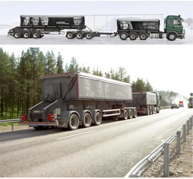
The vehicles that are used to transport the material are 25 m in length (see Figure 3). The maximum allowed load on the steering axle is 9 tonnes and on each triple axle the load is 27 tonnes, resulting in a total gross weight of 1 × 9 + 3 × 27 = 90 tonnes. There are no requirements on the tyre inflation pressure (in an interview in August 2013 Cliffton Mining, the company responsible for the ore transport, were using 900 kPa tyre pressure in all tyres).
Figure 3 The vehicles consist of a steering axle and three tridem axles. The first and the fourth axle have single mounted wheels. All other axles are equipped with dual mounted wheels.
In the beginning it is expected that the ore transport will include around 50 passages per day (in April 2013 the number of passages per day were 90, 45 in each direction) corresponding to about 2 fully loaded passages per hour. As the ore operation gradually increases the number of passages will increase and in 2016 when the ore operation is fully built, 400 passages a day are expected (200 fully loaded and 200 empty). The travelling speed of the vehicles will be 60 – 80 km/hour. (The maximum allowed speed is 80 km/h.) A fleet management system will be used to make sure that the vehicles will keep an even distance along the route.
4
The test sections
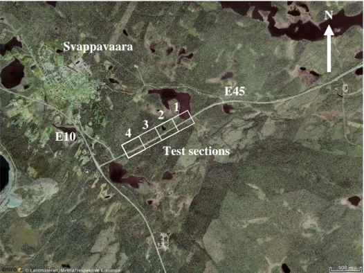
The four test sections are located on E45 close to the intersection with E10 in the vicinity of the Svappavaara village (see Figure 4). The test structures were built in the summer of 2012. The wearing course was placed in the beginning of July 2013.
The test sections were built in a conventional manner on top of an existing road that had been rebuilt in 1975. The old pavement structure was a thin flexible structure with 5 cm AC on top of 15 cm of unbound gravelly base course over a subbase consisting of 65 cm of natural gravel. The top 15 cm of the old pavement were milled and widened in accordance with the new geometric design, leaving a sandy gravel layer on top of the native soil. The remains of the old road structure can therefore be expected to consist of approximately 70 cm of sandy gravel resting on top of the native silty sand subgrade.
Figure 4 Overview of the four test sections.
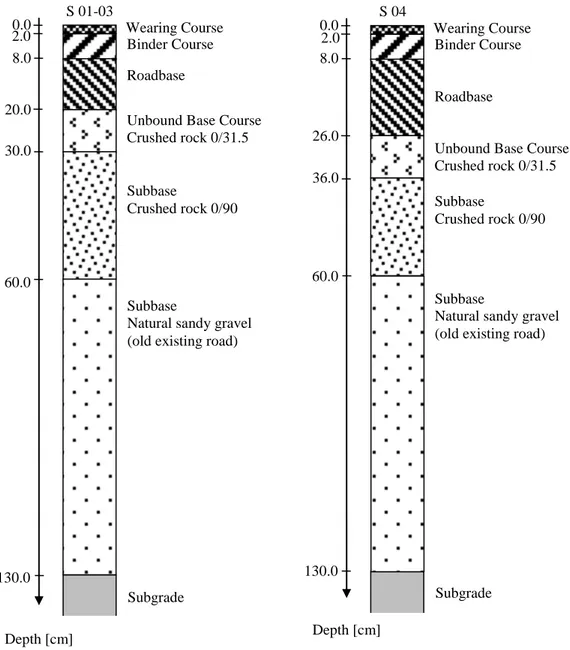
A cross section of the four test structures is given in Figure 5. A more detailed description of the layer composition is further provided in Table 1. The layer
thicknesses of structures 01 - 03 are identical but structure 04 has a thicker road base course, consisting of a cold asphalt concrete mix, and a reduced subbase thickness in order to have the same total thickness as the other structures.
The bitumen bound part of all the four structures consists of three layers; a thin surface course layer, a binder layer and a road base layer. All structures have the same wearing course TSK 16 with pen 160/220 standard bitumen. Structure 03 consists of
conventional bound materials, with pen 70/100 for the binder course as well as for the road base. Structure 01 has a polymer modified binder course as well as a road base whilst structure 02 has the same polymer modified binder course as structure 01 but a more conventional road base. Structure 04 has a conventional binder course but the road base consists of a large aggregates cold mix emulsion with pen 160/220 bitumen.
Svappavaara E45 E10 Test sections N 1 2 3 4
Figure 5 Cross section of the test sections. Structures 01 to 03 have same layer thicknesses. S 01-03 Subgrade 0.0 2.0 8.0 20.0 30.0 60.0 Depth [cm] Subbase Crushed rock 0/90 Unbound Base Course Crushed rock 0/31.5 Roadbase Binder Course Wearing Course S 04 Subgrade 0.0 2.0 8.0 26.0 36.0 130.0 Depth [cm] Subbase
Natural sandy gravel (old existing road) Unbound Base Course Crushed rock 0/31.5 Roadbase Binder Course Wearing Course 130.0 Subbase
Natural sandy gravel (old existing road)
60.0
Subbase
Table 1 Properties of the layers for the four different test structures. Structure 01 02 03 04 Wearing course 20 mm asphalt surfacing TSK16 160/220 20 mm asphalt surfacing TSK16 160/220 20 mm asphalt surfacing TSK16 160/220 20 mm asphalt surfacing TSK16 160/220 Binder course 60 mm ABb22 with Nypol 64-34 60 mm ABb22 with Nypol 64-34 60 mm ABb22 70/100 60 mm ABb22 70/100 Road base 60 mm AG22 40/100-75 + 60 mm AG22 90/150-75 2 x 60 mm AG22 160/220 2 x 60 mm AG22 70/100 2 x 90 mm Large aggregate AC (Viacomac 32) 160/220 Unbound base
course 100 mm Crushed rock 0/31.5 100 mm Crushed rock 0/31.5 100 mm Crushed rock 0/31.5 100 mm Crushed rock 0/31.5 Subbase 300 mm Crushed rock 0/90 + 300 mm Crushed rock 0/90 + 300 mm Crushed rock 0/90 + 240 mm Crushed rock 0/90 + ≈ 700 mm Sandy gravel ≈ 700 mm Sandy gravel ≈ 700 mm Sandy gravel ≈ 700 mm Sandy gravel Subgrade Gravelly till /
sandy silt Gravelly till / sandy silt Gravelly till / sandy silt Gravelly till / sandy silt
A more detailed description of the composition of the bound layers (except the large aggregate AC (Viacomc 32) 160/220) can be found in appendix B in Swedish.
5
Instrumentation and data acquisition system
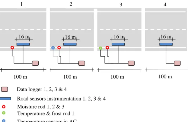
The instrumentation of the test sections can be divided into road sensor instrumentation and climate sensors where the climate sensors consist of a frost rod, moisture rod, temperature sensors in AC layers and a weather station. Figure 6 gives an overview of the instrumentation of the sections.
Each test section is around 200 - 250 m long, with a central 100 m long part defined as the actual test sections. In the remaining parts between the sections some overlapping of layers can occur.
Road performance sensors instrumentation
The road sensor instrumentations are aligned in the centre of the outer wheel path of the road within a 16 m long stretch (see Figure 6). The sensors consist of:
Emu coils for measuring the vertical (both induced and accumulated permanent) strains.
Asphalt strain gauges (ASG) for measuring the transversal tensile strain at the bottom of the bounded layers.
Soil pressure cells (SPC) for measuring the induced vertical stress.
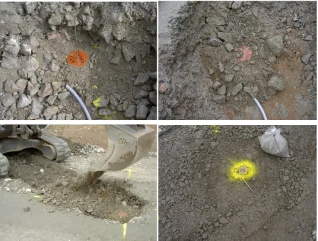
An overview of the sensor locations and the numbers can be found in Appendix A. Figures 7–9 demonstrate the installation procedure of the road performance sensors. For further details of the installation process of sensors, see Saevarsdottir, Erlingsson and Carlsson (2014).
Figure 6 Overview of the instrumentation of the test sections (not to scale).
100 m 100 m 100 m
1 2 3 4
Data logger 1, 2, 3 & 4 16 m
Road sensors instrumentation 1, 2, 3 & 4 Moisture rod 1, 2 & 3
Temperature & frost rod 1
16 m 16 m 16 m
Temperature sensors in AC 100 m
Inductive coil sensors (mu coils)
The mu coils measure deformation between pairs of inductive coils with known distances, hence the strain. They are based on the principle that when an alternating current is passed through a coil of wire an alternating magnetic flux is generated. Another coil placed within this field will therefore generate alternating current directly proportional to the magnetic flux density at that position. The generated signal
magnitude is therefore related to the distance between the transmitting and receiving coils. The Emu coils are produced and calibrated at VTI for measurement of dynamic and permanent vertical deformations (strains).
Figure 7 Installation of Emu coils: a) After compacting a layer a small trench is made to the correct level and the lower Emu coil plate is placed at its right location with a steering rod. b) and c) The material is replaced and compacted. d) The top plate is located on top of the steering rod and the rod removed. Left are two plates on top of each other with known distance between them.
Asphalt strain gauges
The asphalt strain gauges consist of electrical resistance strain gauges embedded within a strip of glass fibre reinforced epoxy, with transverse steel anchors at each end of the strip to form an H-shape. The strain (deformation) is measured over a length of 120 mm. The strain gauges used were of the type PAST II AC produced by Dynatest.
Figure 8 Installation of the asphalt strain gauges: a) Asphalt strain gauges are placed on top of the unbound base course. b) Three asphalt strain gauges are placed in the wheel path but shifted 120 mm to measure the induced transversal strain. c) A chunk of asphalt concrete is placed and compacted over the sensors. d) The asphalt concrete is placed over the sensors.
Induced stresses
Dynamic Soil Pressure Cells (SPC) are sensors used for measuring the induced vertical pressure in unbound aggregates such as base and subgrade layers. The sensors consist of two circular 220 mm steel plates welded together around their rims to create a cell. The space between the plates is filled with liquid. An electrical pressure transducer is mounted outside the pressure cell and connected through a steel tube to the liquid. As loading is applied an electrical pressure transducer is used to convert the liquid pressure to changes in the total stress applied to the material in which the cell is embedded. The SPC’s are produced by Geokon of the type 3500-2-1MPa.
Figure 9 Installation of soil pressure cells: A) After compacting a layer a small trench is made to the correct level and the soil pressure cell placed. b) The removed material is replaced and compacted.
Climate sensors instrumentation
As mentioned earlier the climate sensors consist of a frost rod, moisture rod and
temperature sensors in the AC layers as well as a weather station. A short description of each system is given below.
Frost rod
The frost rod, called Tjälstav 2004, is developed and produced by VTI. It consists of 41 temperature sensors every 5 cm, to a depth of 2 m. The frost rod is connected to a data logger that stores data every half hour. Their depths from the final surface are (cm): 5, 19, 22, 27, 32 ... 212.
Figure 10 The frost rod, called Tjälstav 2004, consists of 41 temperature sensors. An anchor is located at the tip of the rod to restrain any uplift of the rod.
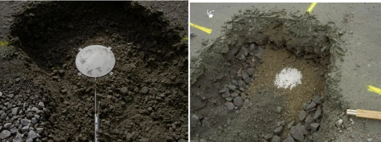
Moisture rod
The moisture rod consists of five time domain reflectometer (TDR) sensors located within a robust 2 m long and 44 mm in diameter PVC rod. The TDR sensors are 200 mm long and their cc distance is 355 mm. The rod is installed below the asphalt
Data transmission (GSM)
Anchor Temperature sensors
Data logger
concrete layers. The mid-depths of the TDR sensors below the surface are 33.0, 68.5, 104.0, 139.5 and 175.0 cm.
Figure 11 a) the moisture rod is 2 m long and consists of five 200 mm long TDR sensors. b) A 300 mm core is drilled through the asphalt concrete layer and the rod installed in a predrilled hole. d) The asphalt concrete is replaced and properly sealed. Temperature sensors
In summer 2013 three temperature sensors were installed in the asphalt concrete layer. They were placed at depths of 2, 10 and 18 cm, respectively. The sensors are connected to a data logger and readings taken every half hour.
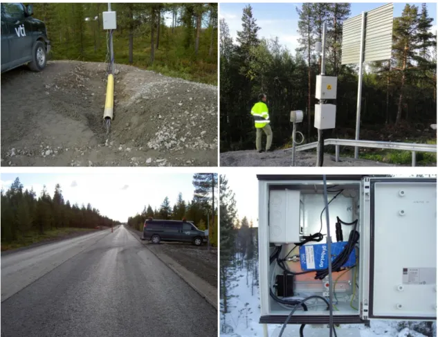
Data logging
Cables from all the instrumentation are gathered in easily accessible storage boxes. As the cables come out of the traffic lane they are placed within a PVC tube for their protection.
200 mm
Figure 12 The storage box with the data loggers.
A weather station (2527 Svappavaara) operated by the Transport Administration is located along E10 3.2 km south-east of the test road sections where data regarding air and surface temperature, precipitation and wind are available.
The wearing course was placed in July 2013(see Figure 13). Information about the wearing course can be found in Table 1.
6
Conclusions
Four new instrumented test road sections have been briefly described. The sections are located in Norrbotten County on E45 in the vicinity of the Svappavaara village about 100 km north of the Arctic Circle. The project is sponsored by the Swedish Transport Administration. Each test section is around 200 m long, consisting of a 100 m long inner part that constitutes the intrinsic test section. The structures were built and instrumented in the summer of 2012 except for the wearing course that was placed in the summer of 2013 along with the temperature sensors that are placed in the asphalt layers.
In 2013 drilled cores were taken from all bound layers for further laboratory analysis as well as disturbed samples from the unbound layers. Response measurements will also be carried out using the actual vehicles as well as a falling weight deflectometer (FWD) device. Long term performance measurements consisting of rut depth and roughness (IRI) based on a Road Surface Tester (RST) as well as high accuracy profile
References
Northland Resources (2014) www.northland.eu [2014-03-15]
Saarenketo, T., Matintup, A., Varin, P., Kolisoja, P., Herronen, T. and Hiekkalahti A. (2012) Pajala Road Impact Analysis - final report, The Roadex project.
(www.roadex.org).
Saevarsdottir, Th., Erlingsson, S. & Carlsson, H. (2014). Heavy Vehicle Simulator Tests at VTI. The International Society for Asphalt Pavements Conference (ISAP 2014), 1-5 June 2014. Raleigh, North Carolina, USA.
Appendix A Page 1 (2)
The location of the road sensors within the 16 m long stretch, for all
the four test roads.
101S 101/102M 102/103S 103M 104M 104/105S 105/106M 106S 108S 108/109M 109/110S 110M 111M 111/112S 112M ASG13 ASG12 ASG11 SPC11 SPC12 SPC13 SPC14 149552 149554 149556 149558 149560 149562 149564 149566 149568 E45 Svappavaara road test - Section 1
Road sensors location
Road surface Binder layer Road base Unb. Base course Subbase Surface existing road Deform. EMU vertical Tensile strain Stress vertical
Old existing road Unbound base course 100 mm
TSK16 160/220 20 mm Module 1 Module 4 Module 4-5 Module 4 Module 1 Module 1-2 AG22 PMB 120 (60+60) mm Module 4 Module 4 Module 1 Subbase 300 mm ABb22 PM B 60 mm Module 1-2 Module 1
Figure A1. Road sensors instrumentation of section 1.
201S 201/202M 202/203S 203M 204M 204/205S 205/206M 206S 208S 208/209M 209/210S 210M 212M 211/212S 211M ASG23 ASG22 ASG21 SPC21 SPC22 SPC23 SPC24 149767 149769 149771 149773 149775 149777 149779 149781 149783 E45 Svappavaara road test - Section 2
Road sensors location
Road surface Binder layer Road base Unb. base course Subbase Suface exisitng road Deform. EMU vertical Tensile strain Stress vertical Old existing road
Unbound base course 100 mm
TSK16 160/220 20 mm Module 1 Module 4 Module 4-5 Module 4 Module 1 Module 1-2 AG22 160/220120 (60+60) mm Module 4 Module 4 Module 1 Subbase 300 mm ABb22 PMB 60 mm Module 1-2 Module 1
Appendix A Page 2 (2) 301S 301/302M 302/303S 303M 304M 304/305S 305/306M 306S 308S 308/309M 309/310S 310M 311M 311/312S 312M ASG33 ASG32 ASG31 SPC31 SPC32 SPC33 SPC34 150012 150014 150016 150018 150020 150022 150024 150026 150028 E45 Svappavaara road test - Section 3
Road sensors location
Road surface Binder layer Raod base Unb. Base course Subbase Surface existing road Deform. EMU vertical Tensile strain Stress vertical Old existing road
Unbound base course 100 mm
TSK16 160/220 20 mm Module 1 Module 4 Module 4-5 Module 4 Module 1 Module 1-2 AG22 70/100120 (60+60) mm Module 4 Module 4 Module 1 Subbase 300 mm ABb22 70/100 60 mm Module 1-2 Module 1
Figure A3. Road sensors instrumentation of section 3.
401M 401/402S 402/403M 403/404S 404M 405S 405/406M 406S 408M 408/409S 409/410M 410/411S 411M 412S 412M ASG43 ASG42 ASG41 SPC41 SPC42 SPC43 SPC44 150257 150259 150261 150263 150265 150267 150269 150271 150273 E45 Svappavaara road test - Section 4
Road sensors location
Road surface Binder layer Road base Unb. Base course Subbase Surface existing road Deform. EMU vertical Tensile strain Stress vertical Old existing road
Unbound base course 100 mm
TSK16 160/220 20 mm Modul 1-2 Modul 4 Modul 4-5 Modul 4 Modul 1-2 Modul 1 Viacomac32 160/220 180 (90+90) mm Modul 4 Modul 4 Modul 1 Subbase 230 mm ABb22 70/100 60 mm Modul 1 Modul 1-2
Appendix B Page 1 (29)
Asphalt Conrete mix composition (in Swedish):
TSK16 160/220 ABb 22 PMB Nypol 64-34 ABb22 70/100 AG 22 PMB 40/100/75 AG 22 PMB 90/150-75 AG22 160/220 AG22 70/100
Appendix B Page 2 (29)
Appendix B Page 3 (29)
Appendix B Page 4 (29)
Appendix B Page 5 (29)
Appendix B Page 6 (29)
Appendix B Page 7 (29)
Appendix B Page 8 (29)
Appendix B Page 9 (29)
Appendix B Page 10 (29)
Appendix B Page 11 (29)
Appendix B Page 12 (29)
Appendix B Page 13 (29)
Appendix B Page 14 (29)
Appendix B Page 15 (29)
Appendix B Page 16 (29)
Appendix B Page 17 (29)
Appendix B Page 18 (29)
Appendix B Page 19 (29)
Appendix B Page 20 (29)
Appendix B Page 21 (29)
Appendix B Page 22 (29)
Appendix B Page 23 (29)
Appendix B Page 24 (29)
Appendix B Page 25 (29)
Appendix B Page 26 (29)
Appendix B Page 27 (29)
Appendix B Page 28 (29)
Appendix B Page 29 (29)
VTI, Statens väg- och transportforskningsinstitut, är ett oberoende och internationellt framstående forskningsinstitut inom transportsektorn. Huvuduppgiften är att bedriva forskning och utveckling kring infrastruktur, trafik och transporter. Kvalitetssystemet och miljöledningssystemet är ISO-certifierat enligt ISO 9001 respektive 14001. Vissa provningsmetoder är dessutom ackrediterade av Swedac. VTI har omkring 200 medarbetare och finns i Linköping (huvudkontor), Stockholm, Göteborg, Borlänge och Lund. The Swedish National Road and Transport Research Institute (VTI), is an independent and internationally prominent research institute in the transport sector. Its principal task is to conduct research and development related to infrastructure, traffic and transport. The institute holds the quality management systems certificate ISO 9001 and the environmental management systems certificate ISO 14001. Some of its test methods are also certified by Swedac. VTI has about 200 employees and is located in Linköping (head office), Stockholm, Gothenburg, Borlänge and Lund.
www.vti.se vti@vti.se