School of Innovation, Design and Engineering
V¨aster˚
as, Sweden
Thesis for the Degree of Bachelor of Science in Engineering
-Aeronautical Engineering 15.0 credits
DESIGN AND IMPLEMENTATION OF
ELECTRICAL LOAD ANALYSIS FOR
CROSS FLEET CONFIGURATION
Martin Saur
msr13002@student.mdh.se
Lena Nikolaisen
lnn13004@student.mdh.se
Examiner: Martin Ekstr¨om
M¨alardalen University, V¨aster˚
as, Sweden
Supervisor: H˚
akan Forsberg
M¨alardalen University, V¨aster˚
as, Sweden
Company supervisor: Celeste Lai,
Scandinavian Airlines System
Denmark Norway Sweden
When aircraft are subject to modifications, the Electrical Load Analysis (ELA) must be updated. Having a well functioning system for documenting modifications is of great importance. Today's lack of a simple, intuitive system for ELA updates makes it a time consuming and com-plicated task to perform. The SAS fleet also consists of multiple aircraft manufacturers, and this makes the updating even more complicated.
This study has two main purposes: (1) To see if the ELA can be updated the same way for Airbus and Boeing, and to find a solution for a semi-automated cross fleet ELA system. (2) If (1) is possible, to document this solution in SAS' CAME-P (Continuing Airworthiness Maintenance Exposition - Procedures).
Data for this study was obtained from research documents concerning ELA, and documents from the aircraft manufacturers were provided from the supervisor, Celeste Lai in SAS. The conclusion was that there were multiple systems on the market for ELA calculations, but most of them were aimed at the design and construction phase of an aircraft, and also too complicated for ELA updates. Airbus had guidelines on how to update ELA, and were also in the process of developing an ELA system that was not launched yet. Analyzing Ser-vice Bulletins (SB), Supplemental Type Certificates (STC), documentation from the type certifi-cate holders, and the system SAS was currently using led to the development of a custom-made Electrical Load Update Spreadsheet, ELUS.
It was concluded that ELUS had to be divided into four sections because of the variety of information provided from the SB's and STC's. ELUS was tested on SB's and STC's, and the conclusion was that it would satisfy SAS' need for updating ELA. Several cascading functions in the forms were programmed to ensure improved reliability. The forms were also protected by a password, to reduce the risk of someone deleting functions or formulas by mistake. Only the admin with the password could edit the sheet and its functions. The filter function in Excel could easily be used in the logs to instantly obtain historical information based on several parameters, such as tail-number, busbar, reference etc.
ELUS was a, by the authors, custom-made spreadsheet solution for ELA updates for airlines with a cross fleet configuration. This meant that ELA updates could be performed in a common document for a fleet consisting of multiple aircraft models and manufacturers. The spreadsheet was designed to be as intuitive and self-explaining as possible, with the aim that all departments in SAS would use it. The avionics department was able to have easy access to modification history on specific aircraft, and the registering tasks could be allocated to the entire group of engineers working on modifications. This way a significant workload was removed from the avionics depart-ment, with increased time to perform other important tasks as a result. Electrical overloads can occur as a result of missing documentation on previous modifications, and aircraft on ground due to such incidents are a huge cost. Electrical overloads are also a major safety hazard for the airline. ELUS was a tool that could help SAS to avoid such situations in the future.
In addition to ELUS, a chapter in SAS' CAME-P concerning electrical load management was written to provide guidelines on how to use ELUS.
Future work could be to upgrade the semi-automation of the spreadsheet to a Visual Basic (VB) programmed spreadsheet with warning functions concerning overloads. VB could also make the procedure of updating multiple aircraft significantly faster. With VB functions implemented, the risk of error would decrease.
This study has been carried out with help from supervisors Dr. H˚akan Forsberg at MDH and Celeste Lai at SAS. The authors of this thesis would like to thank the supervisors for the guidance during this process.
Nomenclature
AC Alternating Current AD Airworthiness DirectiveAh Ampere hours
AP U Auxiliary Power Unit
BAT Battery
BCL Battery Charge Limiter BT C Bus Tie Contactor C/B Circuit Breaker
CAM E Continuing Airworthiness Management Exposition CAM O Continuing Airworthiness Maintenance Organisation CLIM B C/B List Interactive Monitoring Boards
CN T OR Contactor
CP U Central Processing Unit DC Direct Current
DDL Det Danske Luftfartselskab A/S DN L Det Norske Luftfartselskap A/S DOA Design Organisation Approval DOA Design Organization Approval EASA European Aviation Safety Agency ELA Electrical Load Analysis
ELU S Electrical Load Update Spreadsheet ESS Essential
EXT External
F AA Federal Aviation Administration F M EA Failure Mode E↵ects Analysis GEN Generator
GLC Generator Line Contactor GN D Ground
GP U Ground Power Unit GRN D Ground
HU D Heads-Up Display
Hz Hertz
kV A kilo Volt-Ampere
LRM Line Replaceable Module LRU Line-Replaceable Unit LT C Load Tap Changer M EA More Electric Aircraft
P OA Production Organization Approval RAAF Royal Australian Air Force RAT Ram Air Turbine
RCCB Remote Control Circuit Breaker RCV RY Recovery
RP DU Remote Power Distribution Unit SAS Scandinavian Airlines
SB Service Bulletin
SERIES System Electrical Rating Integration Evaluation Software SHED Sheddable
SILA Svensk Interkontinental Lufttrafik AB SOT A State Of The Art
SP T I Siemens Power Technologies International ST C Supplemental Type Certificate
SV C Service
T R Transformer Unit
T RU Transformer Rectifier Unit V AC Volts Alternating Current V B Visual Basic
List of definitions
Normal Operation ”Most probable power consumption in normal operating conditions (flight in normal weather conditions)”. [1]
Maximum Operation “Most probable power consumption in the most unfavourable conditions (flight in bad weather conditions with all circuits in operation).” [1]
Busbar load The arithmetical sum of the related circuit breaker loads.
Power Factor The ratio between the real power (W) to the apparent power (Volt-Amperes). Equipment running in steady state condition has a power factor close to one. PF measures circuit efficiency.
Flight Envelope The flight envelope describes the potential of the aircraft, such as altitude, airspeed or load factor. [2]
Flight phase definition Boeing:
Ground Operation and Loading When the aircraft is parked at the tarmac prior to engine start and departure. The aircraft is provided with power from Auxiliary Power Unit (APU), Ground Power Unit (GPU) (external power source) or batteries.
Taxi Taxi is defined from when the aircraft is first moving with power from own engines to the point where take-o↵ starts on the runway, or after landing and transporting to gate and engine shut-o↵.
Take-O↵ and Climb Take-o↵ and climb starts when the aircraft is at the end of the runway. The aircraft starts the take-o↵ run and leaves the runway. The climb starts when the aircraft has left the runway and ends when the aircraft has reached cruise level.
Cruise The aircraft is in the cruise phase when it is in level flight.
Landing The landing phase starts when the aircraft is using the navigation and indication aids to prepare the landing sequence, to the finishing of the roll-out on ground.
Flight phase definition Airbus:
Nominal Power The nominal power is the maximum electrical load on the system connected to the circuit breaker.
Ground Engines stopped. Aircraft is connected to GPU or powered by APU. Start Engines start.
Roll From the part when the aircraft is leaving the gate to leaving the runway. The roll sequence lasts until the landing gear is not compressed any more.
Take-o↵ The period between when the aircraft has left the runway to 1500 ft. Climb From 1500 ft to a stabilized level.
Cruise The main part of the flight at stabilized level. Descent From cruise level to 800 ft.
Landing From the time the landing is prepared in cockpit to touchdown. Taxiing From touchdown to the moment when the engines are shut down.
Table of Contents
1 Introduction 1 1.1 SAS . . . 1 1.2 Problem Formulation . . . 1 1.3 Hypothesis . . . 1 1.4 Research Questions . . . 1 1.5 Delimitations . . . 2 2 Background 3 2.1 General . . . 32.2 Electrical Load Analysis . . . 3
2.3 Issues . . . 3
2.4 Modifications . . . 4
2.4.1 Service Bulletin . . . 4
2.4.2 Airworthiness Directive (AD) . . . 4
2.4.3 Supplemental Type Certificate . . . 4
2.5 More Electrical Aircraft (MEA) . . . 4
2.6 Future Challenges . . . 5
2.7 Objectives . . . 5
2.8 CS-25 Regulations . . . 5
2.8.1 CS 25.1165 Engine Ignition Systems . . . 5
2.8.2 CS 25.1301 Function and Installation . . . 5
2.8.3 CS 25.1310 Power Source Capacity and Distribution . . . 6
2.8.4 CS 25.1351 Electrical Systems and Equipment in General . . . 6
2.8.5 CS 25.1355 Distribution System . . . 6
3 Method 7 3.1 Literature Study . . . 7
3.2 Experience . . . 7
3.3 Analysis of Current Solution in SAS . . . 7
3.4 Analysis of Available Software on the Market . . . 7
3.5 Prototypes . . . 8
4 State Of The Art - SOTA 9 4.1 Airbus . . . 9
4.2 Boeing . . . 9
4.3 Codarra Advanced Systems . . . 9
4.4 Power System Simulator for Engineering . . . 10
4.5 PowerWorld . . . 10
4.6 Saber Aerospace . . . 10
4.7 SERIES By Marshall . . . 11
4.8 Summary . . . 12
5 Technical Description & Theory 13 5.1 Excel . . . 13
5.2 Visual Basic . . . 13
5.3 Aircraft Electricity in General . . . 14
5.4 Busbars . . . 15
5.5 Aircraft Electrical System . . . 15
5.5.1 Airbus 320 . . . 16
5.5.2 Airbus 330 . . . 17
5.5.3 Airbus 340 . . . 18
6 ELA Guidelines From the Manufacturer to the Airline 20 6.1 Airbus . . . 20 6.2 Boeing . . . 20 7 Results 21 7.1 Functions . . . 23 7.1.1 Error Messages . . . 23
7.1.2 Cascading Drop-Down Lists . . . 25
7.1.3 Buttons . . . 26
7.2 Airbus AC and DC . . . 27
7.3 Boeing AC and DC . . . 28
7.4 Admin Access . . . 29
7.4.1 How to update lists . . . 29
7.4.2 The Log . . . 31
7.5 CAME-P . . . 31
8 Discussion 32 8.1 Common Solution? . . . 32
8.2 The Process of Designing a New Solution . . . 32
8.3 Log Function . . . 34
8.4 Programming . . . 34
8.5 How ELUS Works . . . 34
8.6 CAME-P . . . 35
8.7 Related Research . . . 35
9 Conclusions 36 9.1 Recommendations for Future Work . . . 36
9.1.1 Interface . . . 36
9.1.2 Historical Data . . . 37
9.1.3 Star Alliance . . . 37
9.1.4 Capacity Calculation - Warning Function . . . 37
References 39
List of Figures
1 General electrical wiring diagram Airbus A320 . . . 16
2 General electrical wiring diagram Airbus A330 . . . 17
3 General electrical wiring diagram Airbus A340 . . . 18
4 General electrical wiring diagram Boeing 737-600/700/800 . . . 19
5 Enable Content . . . 21
6 Entry Page ELUS . . . 21
7 The figure shows how buttons are used to navigate in ELUS . . . 22
8 Error message when incorrect format of value is entered . . . 23
9 Error message when letters are entered instead of chosen from drop-down list . . . 23
10 Error message when value is entered instead of chosen from drop-down list . . . 23
11 Error message when a number outside range 0 to 1 is entered . . . 24
12 Error message when a number outside range 0 to 100 is entered . . . 24
13 Error message when letters are entered instead of numbers . . . 24
14 Drop-down list with available aircraft models . . . 25
15 Drop-down list with available tail numbers on A330 . . . 25
16 Drop-down list with available busbars on the chosen tail number . . . 25
17 Transfer to log button . . . 26
18 Example on Airbus Log . . . 26
19 Airbus AC Form . . . 26 20 Airbus AC . . . 27 21 Airbus DC . . . 27 22 Boeing AC . . . 28 23 Boeing DC . . . 29 24 Lists of aircraft . . . 29
25 Aircraft with busbars . . . 30
26 These busbars will be copied to the new tail number in fig 25. . . 30
1
Introduction
The introduction describes SAS, the problem formulation, the hypothesis, the research questions and the delimitations. This will provide a brief overview of the thesis.
1.1
SAS
Scandinavian Airlines was established in 1946 after a merger between Det Danske Luftfartselskab A/S (DDL), Det Norsk Luftfartselskap A/S (DNL) and Svensk Interkontinental Lufttrafik AB (SILA) [3]. Today SAS is also a part of Star Alliance. The SAS fleet consist of 138 aircraft (Oct. 2014). The fleet is divided between 12 long-haul aircraft, 114 short-haul aircraft and 12 regional jets [4]. SAS have ordered 60[5] new aircraft to renew and expand the fleet and to provide good service for the passengers. In 2013/2014 28,4 million people travelled with Scandinavian Airlines together with production companies Blue1 and Cimber. The Passengers can choose between 125 destinations and 807 flights each day [4]. SAS is the largest airline in number of destinations, passengers and flights in the Nordic Region [4].
SAS holds these approvals[6]:
• EASA Part M, Subpart G: Continuing Airworthiness Maintenance Organisation (CAMO) • EASA Part 145: Maintenance Organisation approval
• EASA Part 147: Maintenance Training Organisation Approval • EASA Part 21/G Production Organization Approval (POA) • EASA Part 21/J Design Organisation Approval (DOA)
1.2
Problem Formulation
SAS's fleet represent the following aircraft: Airbus A319, A320, A321, A330 and A340, Boeing 737-600/700/800 and CRJ900 [7]. With this number of di↵erent models to pay attention to, the workload of ELA is extensive. Today's systems are very complicated and complex, and also having both Airbus and Boeing as providers of di↵erent electrical load analysis systems makes it challeng-ing to handle, and also a quite time consumchalleng-ing task.
The ELA provided from Airbus and Boeing is only valid on the original configuration at the time of delivery of the aircraft, but once modifications are done, the ELA needs to be updated.
A uniform system for ELA updates is to be developed for the airline. This system should be a cross fleet configuration, and also be easy to use for all employees involved in the process of updating the ELA.
1.3
Hypothesis
The hypothesis in this thesis is: A common method for Electrical Load Analysis (ELA) for airlines with a cross fleet configuration makes the handling of ELA less complicated and more e↵ective.
1.4
Research Questions
A: Is it possible to follow-up ELA the same way for both Boeing and Airbus fleet? B: Is it possible to develop a method to perform ELA/follow-ups on SAS fleet? C: Is it possible to integrate semi-automated functions?
D: Is it possible to prove method by testing on real cases?
E: Is it possible to create a CAME-P document for ELA management instructions for SAS based on the new simplified system?
1.5
Delimitations
• Bombardier aircraft will not be included in the ELA update sheet. This is decided by SAS. • The ELA updates will only be conducted on busbar level, ripple e↵ect on source level is not
included.
2
Background
The background section is discussing electrical power in general, and also ELA and what kind of issues the airlines are facing concerning ELA and ELA updates. The di↵erent types of documen-tation concerning modifications on aircraft will be described, and also why the ELA is going to be more important in the future and the objects of this thesis.
2.1
General
Electrical power has become an essential part of our lives and way of living today. From electrical power plants, through electrical grids and power distributing networks, to buildings, factories, homes and transportation systems, electrical power is flowing to provide the functions and lifestyle we solely depend on today. Our society is funded on electrical driven components and circuits and most vital systems of cities are electronically controlled. To calculate and dimension these connecting units, special designed software are very important to get a functional and practical overview. There are several developers of software that provide advanced calculations of power, distribution and loads throughout defined grids by the user. Some systems are very sophisticated and opens up for very advanced calculations, something the pricing of the service reflects. Others are free, but they lack a lot of the essential possibilities in circuiting and bus connections that an aircraft represents.
2.2
Electrical Load Analysis
The electrical load is important to monitor on an aircraft especially because replacing or modifying parts may change the total electrical load in the di↵erent phases of flight. By performing an ELA, it is possible to estimate the average and maximum demands the new load put on electrically powered equipment in the di↵erent phases of the flight such as ground operation, loading, taxi, take-o↵, cruise and landing. By using these data it is also possible to calculate the maximum power needed for emergency situations. An electrical load analysis is produced for each di↵erent aircraft type, and it is used as a baseline document for every change made to the aircraft di↵erent parts.
An ELA must be carried out whenever a modification is to be applied on an aircraft. For SAS for instance, the type certificate holder will provide an ELA in paper form or as an excel file on delivery date.
When an aircraft is obtained from other companies or leasing agents, it is important to get an overview on modifications on busbar loads done prior to delivery. This to prevent busbar overloads in future modifications.
After a modification on the electrical system, the electrical load will be changed, and the original ELA will not be valid anymore. Therefore it is of major importance to keep track of how the electrical load has been changed, in case of future changes and the importance of not getting into an overload situation.
2.3
Issues
Today quite a few airlines lack an e↵ective system for ELA calculations, updates and reporting because their fleet consists of aircraft of di↵erent configurations and manufacturers. There are also not many laws and regulations concerning updates of ELA. It is the operators responsibility to document and make sure that the modifications are within the limits of the di↵erent components. The ELA is a complicated and complex operation, and also tedious and time consuming. Because of this, the risk of misinterpretations and mistakes is significant. This leads to a larger workload on the avionics department whenever a design modification is to be implemented, or when an aircraft is to be delivered to another company. The operator taking over the aircraft often want the full history of modifications and load changes. A system that easily can provide an individual log on each aircraft is desirable. SAS want all engineers to be able to update the ELA
even if they are not electrical/avionics engineers. A new, simplified method of updating the ELA would be very helpful.
2.4
Modifications
Modifications on an aircraft can be based on di↵erent documents from either the authorities (AD's), manufacturer of the aircraft (SB's) or supplemental type certificate holders (STC's) that are pro-viding modifications for the airline. SAS is a design organisation and holds a DOA (Design Or-ganisation Approval). Today SAS's modifications are distributed approximately about 60% SB's and 40% STC's.
2.4.1 Service Bulletin
A service bulletin is issued by the airframe manufacturer/engine manufacturer. The purpose of the SB is to enhance the safety or reliability of an aircraft. The SB is not mandatory, and will be analyzed by the airline to see if it is necessary to implement it. An SB can be mandatory if it is required by an AD.
2.4.2 Airworthiness Directive (AD)
As mentioned above, the SB can be made mandatory by an AD issued by the authorities. The AD is announced to correct an unsafe condition. This condition is most likely found in comparable products.
2.4.3 Supplemental Type Certificate
If a company want to develop and produce a product and implement changes to an aircraft it needs to be approved by the authorities. If approved, the company will become a supplemental type certificate holder. When the STC holder issues an STC, the modification has to be approved by FAA/EASA and other relevant authorities.
In the SB and STC the operator will find information concerning the modification such as: Planning information, material information and accomplishment instructions. The SB and STC will also describe which airplanes that are subject to the modification(s), which components that are going to be removed and replaced, how the components are a↵ecting the load, which busbars are involved and the net change in battery amps.
Airbus and Boeing have no control over STC's issued from supplemental type certificate holders. Because of this, the STC designers avoid installing new loads to the essential buses to prevent interference with the operative required and safety related systems.
2.5
More Electrical Aircraft (MEA)
The next generation of aircraft will consist of much more electrically powered solutions and sen-sors, which in turn will lead to the need of total control of electric power distribution, loads and calculations on a di↵erent level than today. By the introduction of the Boeing 787 Dreamliner, a new pace is set in the industry to implement new electronically controlled systems that will replace older, more traditional solutions such as cabin pressurization with bleed air and heating of wing sections with bleed air for ice protection[8]. The implementation of new electrical driven compres-sors for cabin pressure and electro-thermal ice protection on wing surfaces has led to the demand of more generators and batteries for standby power [8]. When the technology of morphing wing structures is ready to be implemented in the production line of aircraft, there will be an additional need for electrical power sources to deliver power for the new technology [9]. Electrical actuators and motors will replace mechanical and hydraulic driven actuators, and this leads to an extended demand of managing the electrical calculations both in the production line of aircraft, but also in the maintenance field. This will be a focus area for airlines in the future when redundancy and sensors leads to less physical maintenance since the system monitors itself, but theoretical
overview and control on loads, busbar limits and electrical distribution within the system will be more important than ever to manage.
2.6
Future Challenges
As the development of aircraft goes in the direction of MEA, the managing software and solu-tions for both ELA calculasolu-tions and monitoring will be more central in the maintenance routines of aircraft. Since the development of hardware and Central Processing Units (CPU) goes in a tremendous speed, it will be only a few years before a finished development of an aircraft is outdated and replacement of CPU and hardware components will be required[10]. Compatibility issues, power distribution changes and load change will be very crucial objectives to monitor. With the amount of CPU's installed in today's aircraft and next generation aircraft's ascending use of computer powered functions, the load performances will change over time.
2.7
Objectives
The first objective is to investigate if it is possible to follow-up ELA the same way for Boeing and Airbus fleet. If so, the next goal is to design one (preferably semi-automated) cross-fleet document for ELA updates that would be easy to use. A common document for both aircraft providers would be a great incentive to allocate the workload across the departments within SAS, and make a complex task easier to handle for all employees working on modifications or replacements on existing aircraft. Therefore it is important to keep the level of simplicity at a level so that it would attract all departments involved to take it into use. In a human factors perspective it is important to customize the sheet to make it as easy to use and logical as possible. By creating a spreadsheet that is adjusted to the information provided from the SB's and STC's it will make the process of updating the ELA less complicated.
The object is to present a simplified semi-automated ELA update method that could be used on all aircraft by all engineers in SAS. This is going to be presented as a spreadsheet. A spreadsheet has proven to be a sufficient method of updating ELA, and SAS is currently using a spreadsheet today for the same purpose. The system is going to be tested on real cases to prove the functionality, and to be documented in SAS CAME-P as an individual chapter in ELA management.
2.8
CS-25 Regulations
CS-25 regulations are defining standards for airworthiness of aircraft. There are subsections defining the electrical system of large aircraft and the standards these should fulfill.
2.8.1 CS 25.1165 Engine Ignition Systems
For electrical power distribution to an engine ignition system, redundancy is mandatory. For batteries supplying power to the engine's ignition, it is mandatory to have a backup system of generators to provide backup power if the battery is discharged. Battery and generator are paired units. The power demand the aircraft represent must overcome the paired units and this at the maximum demand of all electronic functions and ignition of engines at the same time. Failure on generators, depletion on batteries and low rpm on generators are conditions the ignition system must overcome and be operative under. Redundancy and a warning system under certain dis-charging conditions are mandatory. Even the engine's ignition cycle represents an electrical load on the system and must be calculated and made sure are operational under any circumstances. [11, p. 1-E-17]
2.8.2 CS 25.1301 Function and Installation
The modifications or units implemented into an aircraft must be designed for the purpose and perform adequately to the functions intended. If there is a performance envelope this must be tagged, addressed and identified. The implementation to the aircraft must be done correspondingly
to the performance envelope. The cabling must also be of such kind that the regulations and limitations are approved.[11, p. 1-F-1 ]
2.8.3 CS 25.1310 Power Source Capacity and Distribution
If an installation is electrically driven and important for the aircraft's airworthiness by regulations or functionality, it is also required to be redundantly supplied with power. A system must be able to provide power for these essential functions in a diversity of conditions where loss of engine power, failure and engine shut downs on multi-engine aircraft are a possibility. The system must be designed in a way that even in worst-case scenarios there is enough power delivered to the most crucial systems to keep the aircraft in the air and in a satisfactory manoeuvrable way. The number of engines dictates the available capacity, the larger aircraft with 3-4 engines have more generators and batteries available to handle malfunctions.[11, p. 1-F-3]
2.8.4 CS 25.1351 Electrical Systems and Equipment in General
ELA is fundamental for calculating the need of power demanded by the aircraft design and func-tions. The capacity of the aircraft electrical power generators must be large enough to power all functions and is calculated by the loads of all the functions and their power demand. The system consisting of batteries, generators, wiring, busbars, actuators and other electrical components must be constructed for redundancy to be guaranteed. Cross connections and single functionality must be implemented accordingly, so in the case of failure, the functionality of the electronic components can be served by alternative sources or keep their functions operative even though other parts of the grid fail. In a situation where failure is a reality, the system must be able to handle this with-out changing the functionality of the main components that keep the aircraft in the air. All these di↵erent scenarios of malfunctions must be fundamental for the power supply calculations, so in such a scenario the power supplied for the mandatory functions are within limits of the operational area of the item. Changing of power source in such situation must be without disturbance to the system. The crew on the aircraft must be able to disconnect di↵erent sources and monitor electric power distribution within the grid.
The aircraft must be designed consequently so that it has power available in backup in case of fire or failure in such a level that the operational grade of the aircraft is threatening the ability to land or control the aircraft. A backup system in form of batteries, RAT or APU can deliver power parallel to the main electrical system in an emergency situation making it possible for the crew to make a controlled landing. In case of total electrical system failure the crew must have this alternate source available without any specific actions. The functionality of a back up system must cover control of the aircraft, to ensure a controlled landing, and that navigation- and descent/ascent functions are available for finalizing the flight. The system must be designed with redundancy in such a way that loss of the main system and backup system at the same time is extremely unlikely.[11, p. 1-F-9]
2.8.5 CS 25.1355 Distribution System
The distribution system must be designed to secure redundancy. It must be possible to switch sources, locations and wiring cables in case of generator or engine failure. The electrical power from one generator to a physical installation must be cross fed in order to avoid a generator failure leaving the system powerless, the source can be switched and normal functionality of the item can be withheld without disturbance on the performance or system. By cross feeding and cross cabling, redundancy will make sure that installations demanding electrical power can be fed from multiple sources through multiple channels. The source switching must be fully automated without disturbance to the functionality.[11, p. 1-F-10]
3
Method
The method chapter describes how information and knowledge about ELA, aircraft electrical sys-tems, possible solutions and current practice in the airline were gained.
3.1
Literature Study
A literature study has been carried out to get an overview and a deeper insight of how ELA cal-culations are being conducted in di↵erent industries. To find developers of software that would be possible to implement in the airline industry, a great number of companies had to be exam-ined. Literature study as a method for gathering data and gain information concerning di↵erent solutions has given a thorough understanding of how great challenges there are in electrical power calculations. Literature on aircraft electrical and electronic systems has also been helpful to get an understanding of the theory. To get sufficient knowledge in Excel and to understand the possi-bilities that can be used to get the desired result, Internet has been a very helpful resource.
By performing literature studies and discussing ELA update management with the supervisor in SAS, it was clear that there were no good alternatives available for SAS on the market at the moment. Either the systems were very complicated, mainly for design and construction, or not compatible with having a fleet of aircraft consisting of both Airbus and Boeing.
Celeste Lai who was the supervisor in SAS also provided literature from Airbus, Boeing and SAS. SB's and STC's were of great importance for getting an understanding of what kind of in-formation that was provided to the operator when a modification was to be implemented. Also original ELA's from Airbus and Boeing were interesting to look at, to understand the great scope of the electrical system in an aircraft.
Other airlines have probably developed their own solutions, but the airline industry is not sharing their company secrets with their competitors.
3.2
Experience
Celeste Lai's knowledge and experience has been helpful in the process of designing an excel solution that was useful for the purpose. Suggestions and prototypes were analyzed together with her, and based on this adjustments were made.
3.3
Analysis of Current Solution in SAS
The current solution used in SAS has been a guideline in the process of the development of the new ELA update tool.
3.4
Analysis of Available Software on the Market
The research that has been going on in the past by scientists and programmers has led to the software solutions of today. It was therefore important to review these solutions to find strengths and weaknesses. Based on this experience a solution that was custom made for the SAS fleet could be designed.
For the airline industry there are fewer options of suitable software compared to the electrical industry in general, and less tools to solve obstacles that must be overcome to successfully execute the ELA work.
Di↵erent software and corresponding literature available on the market was investigated, the system provided from Airbus and the current practice in the airline. Several providers of ELA systems were also contacted by e-mail to get more information on the di↵erent systems. Based on these methods and systems a simplified way of updating the ELA was going to be presented. One
of the biggest challenges was to find a way that could suit all aircraft in the airline and that was easy enough to use.
3.5
Prototypes
To develop a tool that was suitable for updating the ELA, prototypes were constructed. The prototypes were tested on SB's and STC's, and the need for improvements were identified. This procedure was repeated several times until a fully functioning sheet was developed. This tool was called ELUS (Electrical Load Update Spreadsheet)
4
State Of The Art - SOTA
When an aircraft has reached a certain age, modifications have to be done to maintain the de-sired level of usage, or components have to be replaced with new ones. When introducing new or more electronic components/parts the electrical load on busbars, circuit breakers, inverters (INV), Transformer Rectifier Units (TRU) and generators will change.
The demand for software or programs for keeping track of these modifications is significant, and there are several providers on the market. These systems might be either programs or spreadsheets. What has been discovered is that these solutions are either extremely expensive, too complex to use, mainly for design or construction purposes - not for updates on the electrical load on older aircraft, not compatible with having a fleet of aircraft consisting of both Airbus and Boeing, or the information put into the software is not kept confidential.
Several of these programs/software have been studied, and useful information has been gained on present methods and software available on the market.
4.1
Airbus
In previous years Airbus have delivered their aircraft with a paper version of ELA at the time of delivery. Aircraft delivered from 1st October 2002 come with an excel file containing ELA data that can be updated due to modifications. The airline is responsible for updating the ELA doc-uments throughout the lifetime of the aircraft. Airbus have no responsibility for providing such services.
Customers have asked Airbus to develop a tool to help keeping track of ELA updates after implementing modifications on aircraft post delivery. Airbus o↵er no current tools available for this purpose. In July 2014 Airbus introduced a tool prototype called CLIMB (C/B List Interac-tive Monitoring Boards)[12] based on feedback from customers. This tool is supposed to make the process of the ELA and validating a modified load easier and less time consuming. This tool is not launched yet.
Airbus have also developed a software called Electrical Load Analyzer (ELAN)[12] that is used within the organization. This program is directed to ELA specialists, and is not suitable for untrained sta↵.
4.2
Boeing
At the moment Boeing does not provide any system or method for updates on the ELA. The manufacturer is not obliged to o↵er such services, and the airlines have to find solutions that work well for themselves. SAS have a spreadsheet solution for their Boeing aircraft.
4.3
Codarra Advanced Systems
Codarra Advanced Systems is an Australian company that delivers ELA software for industry applications. The software was released in 2004 after close collaboration with the Australian Air Force.
The ELA software from Codarra is not spreadsheet based, but is programmed and designed to as Codarra describes it; “model electrical loads of complex systems” [13, p.1 ELA flyer]. The software is depending on heavy computer resources since the calculations are demanding and need great CPU power. Thousands of calculations must be processed to determine performance over numerous concatenated scenarios, and therefore the price of developing this software reflects the cost of buying a license. One user agreement for the Codarra software is 30 384 USD and a server maintenance fee of 4 861 USD a year [13].
Codarra Advanced Systems o↵er tools for calculations on a broad spectrum of platforms. Green and eco friendly houses, cars, military transport vehicles and aircraft are integrated in this software [13, p. 2 ELA flyer]. For advanced load calculations the software from Codarra has been chosen to calculate the loads on Australia's fleet of Black Hawk helicopters. Lockheed Martin implemented the tool and incorporated it in the ELA work of their production line of Hercules C130's [14]. The ELA Software from Codarra Advanced Systems satisfies the MIL-E-7016F standard and is therefore ready to be implemented in aerial systems. The software can be applied on both civilian projects and defence systems in air, ground and at sea. The US Navy has also decided to use this software in their ELA calculations and bought a license.
As stated from Codarra Advanced Systems “the ELA software can analyze how much electricity you can use on your vehicles against the generating capacity of the system” [13, p.1 ELA flyer]. Codarra enables analyses covering the di↵erent conditions in flight, from take-o↵ to landing, which is very important for ELA in airlines. The program lets the engineers draw the electrical circuits and visualize the network for accurate load and performance calculations. Identified overloads are warned so the engineers can find alternative busbars to connect the new load.
4.4
Power System Simulator for Engineering
Power System Simulator for Engineering is software provided by Siemens Power Technologies International (SPTI). Python scripting enables automated functions and programming for power flow analysis. The software enables graphical visualization and customization of the calculations. The system opens up for electrical circuits consisting of up to 150 000 buses. Siemens states that the software opens for “cascading failure vulnerability analysis” [15].
4.5
PowerWorld
PowerWorld o↵ers simulator and software for advanced and complex systems consisting of high numbers of buses. The possibility of visual design as basis for calculations are also implemented here, and systems of up to 60 000 buses can be designed and calculated. PowerWorld states that “PWS supports detailed modelling of Load Tap Changer (LTC) and phase-shifting transformers, switched shunts, generator reactive capability curves, generator cost curves, load schedules, trans-action schedules, dc lines, multi-section lines, and remote bus voltage control” [16]. The software enables for analysis and calculations of changes that are made to the system, and for verification that these are made correct. The simulator uses one-line diagrams very much like Multisim, and the software lets engineers draw circuits and full diagrams of busbars and generators.
License is stated to be 10 000 USD for the first seat, and the next 2-5 seats are 5000 USD each and these costs are for the basic simulator without add-ons. There are yearly maintenance fees and only one-year free upgrades and support. Site license is set to be 30 000 USD and a full Site License of Simulator with all add-ons is priced to 279.000 USD [17].
4.6
Saber Aerospace
Saber is a Microsoft based platform used by aircraft design teams world wide for calculations, sim-ulations, modelling, analysis, visualization, wire harness design and Failure Mode E↵ects Analysis (FMEA) [18, p. 3]. Saber is used in various industries such as the automotive, aerospace, energy systems and power distribution industry. The idea behind Saber is that by using such software, one can test and verify configurations and systems at the design stage before the actual configura-tion/system is built, and thereby verify that the desired level of reliability and safety is reached. This saves a great amount of time and money in the design process. Saber RD is easy to use, but should also have extended functions for users with higher demands and it is based on a Windows platform. It is possible to connect Saber to 3-D tools such as Catia V5, Siemens (UGS) and Pro/E. It is also possible to integrate with: MATLAB/Simulink, Zuken, Mentor Graphics, Cadence, Syn-opsys VCS [19]. The future in aviation is leading towards MEA, and the aircraft systems need
to be robust. Analysis done by Saber can tell how the loads are a↵ecting the performance of the aircraft, and if it is necessary to find alternative solutions.
4.7
SERIES By Marshall
Marshall Aerospace and Defence Group with their main office in Cambridge UK have specialized in “Conversion, modification, maintenance and support of civil and military aircraft, defence vehicle engineering, shelter manufacture, composite solutions and the provision of personnel, training and advice” [20].
Marshall got the chance to together with the Royal Australian Air Force (RAAF) develop a software based tool to calculate electrical loads or to simulate loads when new configurations on the original power system architecture was introduced. Marshall had seen the demand for such tool over a long period of time, but couldn't develop it because of the cost. Earlier they had used a spreadsheet solution. When the RAAF were interested in such tool for its C-130 series aircraft, Marshall Aerospace and Defence Group finally got the opportunity.
The spreadsheet has been the preferred method because of the possibilities of calculating the electrical loads, but it also has its downsides. Marshall have experienced that the extent and complexity of the spreadsheets were significant, which in turn lead to a higher probability of risk being done in the process. Too much time was used to make sure that the result was real. It was not possible to show spare capacity of the di↵erent components. This was not necessary, but a very helpful tool that was possible to implement in a di↵erent type of software. Marshall wanted to develop software that was easier and more visual. They developed a software called SERIES (System Electrical Rating Integration Evaluation Software) based on RAAF's fleet of C-130. A “skeleton” with all components and how they were connected to each other was created. Genera-tors, INV's, TRU's and batteries were added and coded with colors depending on if it was AC or DC power. Arrows explained the direction of the connectivity logic. If a component was exchanged or modified, it was possible to load/unload the desired power bus on the skeleton. “Intelligence” was added to the software, so if a load was placed on a bus with insufficient power available, the system could not validate the new load. This function had seemed to be hard to implement in a spreadsheet. Also, if one tried to place a load on a bus that could not deliver the right kind of power type, it was impossible to accomplish the placement. Some components even need di↵erent power supplies; the software would detect this and would warn the user if the power supplies were insufficient. No validation would be possible until sufficient power supplies were connected.
The most critical situation in an electrical system is if one or more power sources fail to generate power. The ELA visualizes di↵erent phases of flight and even critical situations such as loss of generator power. SERIES even shows how the alternative sources take over the power distribution if a main power source fails. With the possibility of showing the di↵erent loads in di↵erent phases of flight and even emergency, it was easy to document that a certain modification could handle the loads and be possible to carry out.
SERIES was designed to support three levels of users: Normal user, super user and adminis-trator. Normal Users could simulate modifications on a temporary basis, the Super Users could do permanent changes to the loads. This reflects the system with “checked by” and “sign o↵” proce-dures in real life. The Administrator had full access to the functions and data in the software, and could also edit and add new configurations. The Administrator could also extract information to tables, charts and reports. When a change of design is approved, the ELA can be updated by the Super User and stored in the archives.
4.8
Summary
Airbus' tool is still not released, so it is hard to say of this solution could fit SAS's needs. Since it is a tool customized for Airbus it would probably be a challenge to perform ELA updates on Boeing the same way.
Codarra is a software for advanced load calculations and also a quite expensive tool. SAS do not need such a complicated tool at the moment, and it is not necessary to spend this amount of money on software that will not be used to its full extent.
One problem with commercial products like PowerWorld and Power System Simulator for Engineering, is that these products do not support intermediate calculations. These softwares support basic systems and show only final results. The operators are dependent on calculations on intermediate loads.
The airline will have to compute sensitive data, which they don't want public. The developers only o↵er licencing agreements which means that the airline doesn't own the product/software they are using.
There is also a question about support of software; if routines within an organisation are imple-mented and the software used for solving the problems suddenly are replaced with never editions, compatibility issues may occur. Both when it comes to software as well as hardware. For the organisation to be fully reliable on the software producer, problems may raise if the producer find the older versions not being economically sustainable for upgrades to newer hardware. The cost of adjusting the system to the desired line of business is also high.
Saber is too complex and meant as a tool for design teams in the aircraft manufacturing indus-try, and is not usable just for updating ELA on an existing fleet of aircraft.
SERIES looks like an interesting software with a good user interface. On the other hand it seems to be too advanced to use for ELA updates and documentation. The price of a user licence is unknown.
Since SAS don't need advanced and expensive solutions such as Codarra, PowerWorld and Power System Simulator because they at present time don't perform advanced design changes or construct aircraft electrical systems. A well designed excel sheet with all necessary functions would be a good and less expensive solution that could suit SAS' needs.
Musti and Ramkhelawan [22] also concluded that solutions based on Excel/Spreadsheet was easier to update, was more economical and had a longer lifetime. Exporting information for use in reports was also easier.
5
Technical Description & Theory
To develop a tool that could solve the challenges concerning electrical load management, it was important to gain knowledge about aircraft electricity. It was also important to find a suitable platform. The technical description explains why Excel was chosen and describes the aircraft electricity in general.
5.1
Excel
Excel was chosen as the preferred software because it has several advantages:
• Programming with macros is possible. This can be used to get semi-automated functions in the spreadsheet.
• It can handle large amounts of data. • It can be customized to a desired layout. • It is easy to export data between sheets.
• The sheets can be protected with passwords to ensure that no functions are edited by mistake. • It is easy to handle and edit.
• Formulas can be implemented.
• Excel is well known to the target group.
• SAS is currently using Excel for their ELA updates today. • It was available for us.
By creating an excel-sheet with all necessary functions, it was possible to fulfill the requirements that are needed to update and manage electrical load changes.
5.2
Visual Basic
Initially Visual Basic (VB) for Excel was the software used for getting the desired layout, but it turned out to demand quite a lot of knowledge of programming the codes that was necessary for getting the functions needed for the di↵erent ELA updates. Because of this, the decision of using regular Excel was taken, otherwise a lot of time would have been spent on learning programming in Visual Basic. This was not the purpose of this thesis, and it was possible to get a result that was almost equally good in Excel. People both in Sweden, India and USA was contacted to get support with programming in VB, but no one had the opportunity to help us.
Also programming buttons and lists with cascading functions would involve a lot of coding, which in the end would end up as a quite complicated code. Regular Excel macros were chosen despite the fact that programming in VB would make the result look better, the functionality would be almost the same.
5.3
Aircraft Electricity in General
Aircraft electricity is mainly created by generators in the aircraft. There are several configurations on how these are placed within the aircraft, and they are all individually adapted to the aircraft design. In an aircraft the number of electronically controlled functions will declare how many generators that must be installed. The generators must be able to deliver enough power for all the functions to operate in worst-case scenarios with redundancy for eventual failure situations. [23, p. 80]. For example, the new Boeing 787 Dreamliner uses electricity to pressurize cabin air and also electricity for anti icing the aircraft's wing leading edges. This requires an extensive use of generators compared to the traditional way in the industry, which is solving this with the use of bleed air from the engines. Batteries together with generators supply the aircraft's need of power, and batteries provide standby power in the case of generator failure only. The TRU converts AC generated electricity from the generators to DC for charging of the batteries. Inverters do the opposite by inverting DC electricity to AC electricity and this way an aircraft can have both DC and AC generators combined with batteries and TRU/INV to provide all the required electricity for di↵erent applications [23, p. 104-105].
For supplying di↵erent voltage and amps through the aircraft, busbars and connectors dis-tribute the power generated in the generators. Busbars enhance the possibility to disdis-tribute cor-rect power to the requirements of the application. The galley is one of the most power demanding installations[23, p. 162] in an aircraft, and this system requires 115V/400HZ AC electricity. Smaller loads are served 28V DC like the cockpit instruments. The heating pads on the aircraft's wings require a higher voltage and amps than the Heads-Up Display (HUD) in cockpit displaying data. Therefore the required power to the wing section is distributed from one Remote Power Distribu-tion Unit (RPDU), and another distributes the lower amp and voltage needed by the HUD in the cockpit section. Aircraft have Auxiliary Power Unit (APU) installed for starting the engines on ground [24, p. 415]. The APU can provide pneumatic pressure, electric power or hydraulic power for the purpose to start the main engines of the aircraft [23, p. xi]. For a turbine engine to start, it needs a certain amount of momentum for being self-sustained with air compression. To achieve the turning of the engines the APU [25, p. 76] is started and provides the energy needed to get the turbine rotating.
MEA use more generators and needs larger battery capacity for emergency situations, but the winnings are less fuel consumption and lighter aircraft, which leads to longer range. The use of more electricity changes the layout of the aircraft design, and removes ducts and heavy titanium tubing from the bleed air system on the engines [8], and the Ram Air Turbine (RAT) is removed. Aircraft goes through extensive certification and testing phases to ensure everything holds the standards set by the authorities. In the production phase this means that electrical wiring and electrical components will be installed and tested over and over again in both laboratories and dur-ing extensive test flights. Since the wirdur-ing and installed components ages with the aircraft itself, the chance of error increases with every year [26, p.12.D.3-2]. The components can be exchanged, but the wiring is seldom replaced. It is important that the focus on electrical wiring is raised, since it is such a crucial system of an aircraft and even more central in the next generation aircraft. To avoid future catastrophes, the awareness must be raised and wire health management must be implemented as one of the key elements in aircraft maintenance.
The electric power in an aircraft is driving a high number of functions, and the next generation aircraft are even more electrical driven. Generators, batteries and wiring are only three of the sub-stances in the electrical system. But antennas, sensors, actuators, transformers, Line-Replaceable Units (LRU’s) and Line Replaceable Modules (LRM’s), relays and power distribution panels are also part of electrical systems in aircraft. Direct Current (DC) motors and actuators will be heavily present in next generation aircraft as well. All these components are connected with wiring and in the Airbus A380 it is about 500 km of wiring [27]. With the length of cable present in aircraft today the risk of error also dramatically increases.
5.4
Busbars
As mentioned earlier, the busbars are a part of the electrical distribution system. One side of the busbar is for connecting to protection devices such as fuses or circuit breakers (C/B), and the other side is connected to a power source such as a generator, INV, TRU or battery. The function of a fuse or C/B is to protect the busbar in case of an overload situation occurs.
The buses have di↵erent tasks in the system:
• The main bus: This bus consists of loads that are non-essential in the aircraft. If an emer-gency occurs, such loads can be removed without a↵ecting the safe handling of the aircraft. Examples of such loads are: In-flight entertainment, galley and main cabin lights.
• Essential bus: The safety bus in the aircraft. This bus is connected to equipment and instruments needed for operating the aircraft safely.
• Battery bus: The battery bus ensures that equipment needed for operating and landing the aircraft in an emergency situation is provided with sufficient power.
5.5
Aircraft Electrical System
The aircraft wiring diagrams that displayed the general systems were studied during the literature study. As an objective stated from SAS, understanding the electrical system in an aircraft was important before the design of an ELA update spreadsheet. The aircraft had some individual di↵erences; The Airbus A340 had 4 engines and therefore more generators, and as a consequence more AC busbars than other aircraft models. Since the definitions of these were di↵erent, it was important to implement a system that separated the di↵erent types of busbars from the di↵erent aircraft models. This resulted in the development of cascading drop down lists that were dependent on each other for registering aircraft model, tail number and busbar name. This way the di↵erent aircraft models and corresponding busbars would only be available in drop down lists. This solution was derived to make sure that the filtering function would work properly. The chapters 5.5.1 -5.5.4 show the di↵erent aircraft electrical systems in general and how they di↵er from each other.
5.5.1 Airbus 320
Main units, see figure 1: Auxiliary Power Unit (APU), Battery Charge Limiter (BCL) shown as BAT CONT, Alternating Current (AC) BUS 1 and 2, AC Essential (ESS) BUS and Sheddable (SHED) BUS , DC BUS 1 and 2, DC Battery (BAT) BUS , ESS TR, HOT BUS 1 and 2, DC ESS BUS and SHED BUS, RAT shown as EMER GEN, Generator Line Contactor (GLC) , Bus Tie Contactor (BTC) , TRU and Inverter (INV).[28, p. 260-261]
Figure 1: General electrical wiring diagram Airbus A320
Electrical power system: 115 Volts Alternating Current (VAC) , 400 Hertz (Hz) provided by generators from both engines. Electrical power sent to AC BUS 1 and AC BUS 2. AC BUS 1 distributes power to AC ESS BUS and to the AC ESS SHED BUS via via AC ESS FEED. AC BUS 2 distributes power to AC ESS BUS and to the AC ESS SHED BUS via via AC ESS FEED redundantly. Cross feeding functions for AC BUS 1 AND AC BUS 2. The TR1 rectifies AC to DC from AC BUS 1 to 28 Volts Direct Current(VDC) DC BUS 1. It also distributes DC to the DC BATTERY BUS. DC ESS BUSES are also provided DC from TR1. The TR2 rectifies AC from AC BUS 2 to the DC BUS 2. DC TIE CONTACTOR connects DC BUS 2 to DC BAT BUS which supplies HOT BUS 1 and two through the BCL(shown as BAT CONT). AC ESS BUS also provides power to the DC ESS BUS through ESS TR which rectifies AC to DC power. The RAT or EMER GEN provides redundant power to ESS TR [29, p. 3.4].
5.5.2 Airbus 330
Main units, see figure 2: DC BAT BUS, HOT BUS 1 and 2, DC ESS BUS, DC BUS 1 and 2, DC ESS SHED, AC LAND Recovery(RCVRY), APU Transformer Rectifier (TR), TR 1 and 2, SHED LAND RCVRY, DC LAND RCVRY, STAT INV, AC ESS Ground(GRND), AC ESS BUS, AC ESS SHED, AC BUS 1 and 2(Cross feed implemented), Generator(GEN) 1 and 2 and APU GEN [30, p. 3.2].
Figure 2: General electrical wiring diagram Airbus A330
Electrical power system: 115 VAC and 200 VAC 400 Hz, 28 V DC. GEN 1 provides power for AC BUS 1, GEN 2 supplies AC BUS 2, where both External (EXT) B, EXT A and APU GEN powers both AC BUS 1 and 2. TR1(TR) rectifies AC from BUS 1 to DC BUS 1, TR2 rectifies AC from BUS 2 to DC BUS 2. Both DC BUS 1 and 2 powers DC BAT BUS.AC BUS 1 and 2 also supplies AC ESS FEED and ESS TR rectifies AC to DC power to DC ESS BUS. APU TR rectifies AC power from AC BUS 2 to DC power for the APU START [31, p. 2].
5.5.3 Airbus 340
Main units, see figure 3: 4 AC generators, APU, EMERGENCY GEN, INV, 2 BATTERIES, GROUND CONNECTOR, DC BUS 1 and 2, DC ESS BUS, DC ESS SHED, AC BUS 1, 2, 3 and 4, AC ESS GROUND, HOT BUS 1, 2, DC LAND RCVRY, SHED LAND RCVRY and LAND RCVRY [32, p. 3.2].
Figure 3: General electrical wiring diagram Airbus A340
Electrical power system: The system delivers 115/200 VAC, 400 Hz, 28 VDC. 4 generators, one on each engine supplies the AC BUSES 1, 2, 3 and 4 with total of 300 kilo Volt-Amperes(kVA). AC BUS 1-2 to TR1, which rectifies AC power to DC power sending it further to DC BUS 1. AC BUS 2-3 sends power to DC BUS 2 through TR2, which rectifies AC to DC power. AC BUS 1-1 and AC BUS 2-4 connects to AC ESS FEED. AC ESS FEED connects to AC ESS SHED BUS but also the ESS TR, which rectifies AC to DC to the DC ESS BUS. AC BUS 2-4 also provides APU TR CNTOR(Contactor) through APU TR for APU START. HOT BUS 1 and 2 provided by DC ESS BUS to DC BAT BUS, together with both DC BUS 1 and DC BUS 2. 2 Batteries charged and provided power by HOT BUS 1 and 2, 2 x 75 Ah(Ampere hours) [33, p. 2].
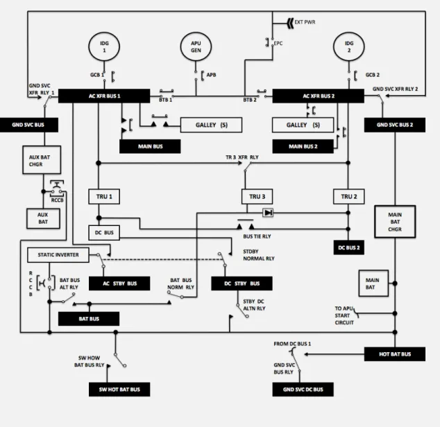
5.5.4 Boeing 737
Main units, see figure 4: APU GEN, IDG 1 and 2, AC XFR BUS 1 and 2, MAIN BUS 1 and MAIN BUS 2, GND(Ground) SVC(Service) BUS 1 and 2, TRU 1, 2 and 3, MAIN BAT BUS, GND SVC BUS 1 and 2, DC BUS and DC STBY BUS, AC STBY BUS, BAT BUS, HOT BAT BUS, GND SVC DC BUS 1 and 2, SW HOT BAT BUS, STATIC INVERTER, Remote Control Circuit Breaker (RCCB) and EXTERNAL POWER[34, p. 11].
Figure 4: General electrical wiring diagram Boeing 737-600/700/800
Electrical power system: 115 VAC, 400 Hz provided by generators from both engines, total of two. APU GEN, IDG (GEN) 1 or 2 or AC BUS (external power) sends AC power to AC XFR BUS 1 or 2 (GEN 1 to AC XFR BUS 1, GEN 2 to AC XFR BUS 2), cross feed implemented. AC is rectified from TRANSFER BUS 1 and 2 through TR1 or TR2. Power then goes to DC BUS 1 or 2. Also from 115V AC MAIN BUS 2 (source is GEN BUS 2) is power sent through TR 3 to the BATTERY BUS. BATTERY BUS powers DC STANDBY BUS and INV sends power from BATTERY BUS to AC STANDBY BUS. 115 VAC GND SERVICE BUS powers BATTERY CHARGER and this charger sends power to APU START, HOT BATTERY BUS, SWITCHED HOT BAT BUS, EXTERNAL DC RECEPTACLE and BATTERY. 115V AC MAIN BUS also powers the BATTERY CHARGER during flight [34, p. 11].
6
ELA Guidelines From the Manufacturer to the Airline
When a modification is to be implemented on an aircraft, the manufacturers provide di↵erent guidelines on how to update the ELA.6.1
Airbus
Airbus provide a set of guidelines when it comes to implementing modifications due to SB or STC [35]. These guidelines are supposed to make the handling of STC and SB easier. This document gives the engineer an overview of what kind of ELA formats there are. It also contains the calculation methodology on di↵erent levels, such as busbar, converter and generator. The guidelines also describe di↵erent rules for validation and installation of SB and STC.
6.2
Boeing
There are no guidelines from Boeing concerning ELA updates. The operator has to follow the paragraph that is concerning “Electrical Load Data” in the SB. This paragraph describes how the new electrical loads are changed.
7
Results
In this chapter ELUS and its functions are described.
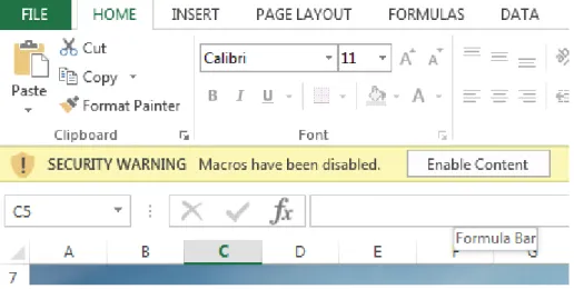
The first thing that has to be done when using ELUS is to enable macros by clicking on “Enable Content” when opening Excel, see figure 5. If macros are disabled, the tool, which is based on macros, will not function correctly.
Figure 5: Enable Content
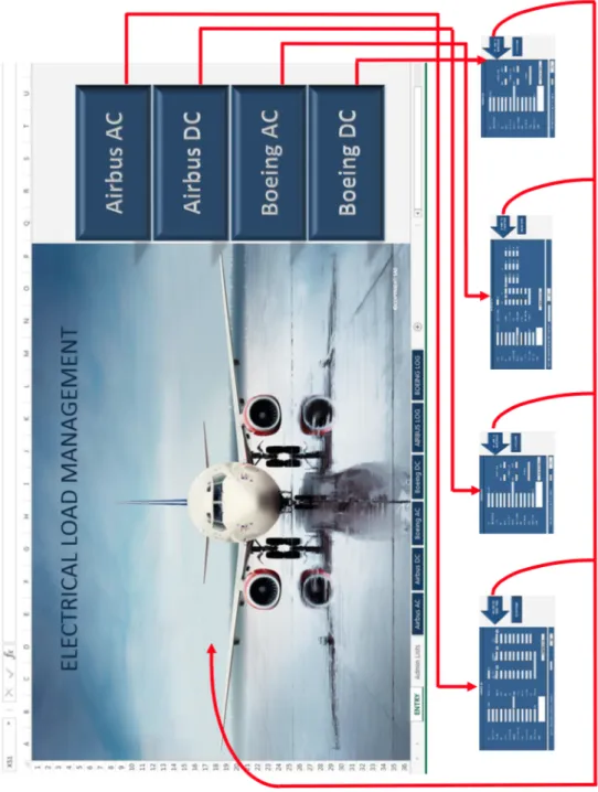
Because there was a need for dividing ELUS into four sections, an entry page was designed, see figure 6:
Figure 6: Entry Page ELUS
By using the buttons in ELUS it is possible to navigate between the spreadsheets as shown in figure 7.
7.1
Functions
7.1.1 Error Messages
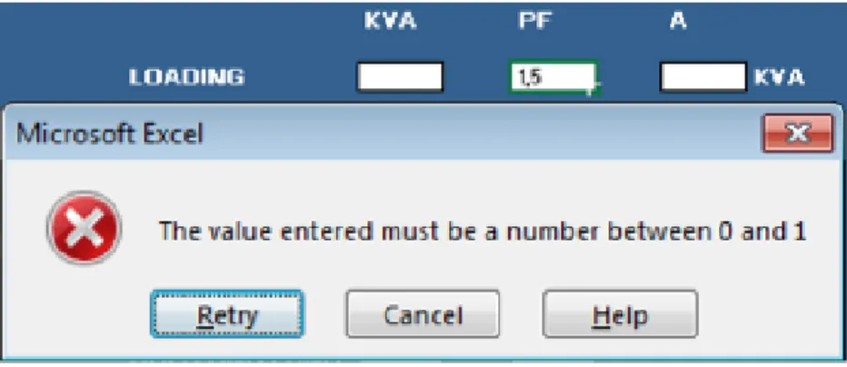
ELUS is based on information that is provided in the SB's/STC's. To make the risk of entering incorrect information as limited as possible, several warning functions have been added to the sheet. Keeping the same format is also important based on the fact that the log is going to be used as an archive. In order to use the filtering functions the best way possible, all parameters should be formatted the same way to get the best results when filtering. By introducing warnings to the cells to keep formats the same, the output will be optimised. The warnings will appear if in-correct values are entered into the cells. The most common error messages are shown in figures 8-13.
Figure 8: Error message when incorrect format of value is entered
Figure 9: Error message when letters are entered instead of chosen from drop-down list
Figure 11: Error message when a number outside range 0 to 1 is entered
Figure 12: Error message when a number outside range 0 to 100 is entered
Figure 13: Error message when letters are entered instead of numbers
It is possible to enter both positive and negative numbers in the operational/maximum load cells. Some modifications involve removing loads, which means that negative numbers has to be allowed.
It is not possible to enter letters into the cells where values are to be entered. This is because it must be possible to calculate the sum of loads in the log function, and if there are letters together with the numbers, this will not be possible.
7.1.2 Cascading Drop-Down Lists
To make ELUS semi-automated, cascading drop-down lists were programmed. This means that when an aircraft model is chosen, see figure 14. The corresponding tail numbers will be available in the drop-down list in the cell below, see figure 15 (only on Airbus aircraft). The corresponding busbars will also be available further down in the form, see figure 16. This is programmed for all aircraft models. Because of this semi-automatising the risk of making mistakes and the time consumption is reduced.
Figure 14: Drop-down list with available aircraft models
When the correct model is chosen, the correct tail number shall be selected:
Figure 15: Drop-down list with available tail numbers on A330
The busbars will be adjusted to the aircraft model:
7.1.3 Buttons
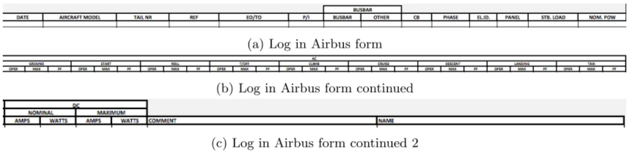
Another function that contributes to making ELUS semi-automated is buttons. By recording macros it was possible to insert buttons that had useful functions in the form. The “Transfer To Log Button”, see figure 17, will copy all information entered in the form to the log below, see figure 18. The information will also be sent to a separate log sorted on the specific aircraft manufacturer as shown in figure 27.
Figure 17: Transfer to log button
All entered information in the sheet will be relocated to the log section:
(a) Log in Airbus form (b) Log in Airbus form continued
(c) Log in Airbus form continued 2
Figure 18: Example on Airbus Log
In figure 19 is the Airbus AC form displayed with all it's functions and accompanying log:
Figure 19: Airbus AC Form
In some cases will all phases of flight have the same value. By pushing the “All”-button, the value in Ground phase will be copied to all phases below.
7.2
Airbus AC and DC
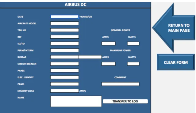
The Airbus AC/DC forms are based on information provided in the SB's/STC's. The forms are shown in figure 20 and 21.
Figure 20: Airbus AC
7.3
Boeing AC and DC
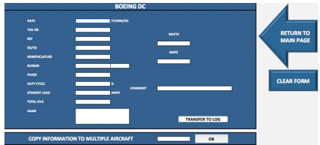
The Boeing AC/DC forms are based on information provided in the SB's/STC's. The forms are shown in figure 22 and 23.
Figure 23: Boeing DC
7.4
Admin Access
ELUS is designed to be easy to manage and update. All necessary information about aircraft models with corresponding tail numbers, busbars etc. are gathered in the Admin sheet as lists. For safety reasons is the Admin list protected by a password to make sure that no editing is done by mistake. By entering the correct password it is easy to add/remove items on the lists. These lists are used to get the cascading list functions on each SB/STC.
7.4.1 How to update lists
Figure 24: Lists of aircraft
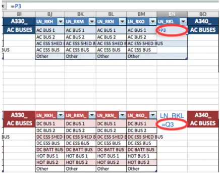
By entering the new aircraft tail number in the space in the red circles in figure 24, the cascad-ing drop-down lists in the correspondcascad-ing sheets will be automatically updated. For the busbars to connect to the tail number another action has to be done:
On the right hand side of the admin sheet all aircraft are present with busbars. Insert a new column in the area with correct Aircraft Model shown in figure 25. First a new column has to be inserted, then the new tail number has to be entered in BN1 and BN15. Then enter =P3 in BN2 to connect to the correct list of AC busbars, see figure 26. Enter =Q3 in BN16 to connect to the correct list of DC busbars, see figure 26. All busbars will then automatically appear in the column.
7.4.2 The Log
When all information in the SB or STC is entered in the correct form, it will be moved to the log below the form, but also to a historical log sorted on Airbus or Boeing aircraft, see figure 27.
The log below the form is only for the user to have a visual reference to see what has been entered and transferred to the log earlier, the main log is a powerful tool for the engineers. The main log is based on copies of the logs found in the forms, but it will gather all modifications on all aircraft in the fleet. By using the filter function it is possible to get information on what has been done to a specific aircraft, how much the load has changed on a busbar, it can be sorted by SB/STC numbers. The user can also sort the log by defining multiple parameters. It was not possible to have a common log on Airbus/Boeing because of di↵erent input in the forms. ELUS contains two main logs, one for Airbus and one for Boeing aircraft.
By sorting the log on tail number and busbar, and calculating how much the specific busbar has been modified, it is possible to calculate how much spare capacity that is available.
Figure 27: The filter function
7.5
CAME-P
After ELUS was designed, a chapter on Electrical Load Management in SAS' CAME-P was written. This chapter is illustrated in Appendix A.