QoS Analysis for Signaling in VoIP
Client and Server Communication
for Multicore
Muhammad Adnan
April, 2012
Master of Science Thesis
Stockholm, Sweden 2012
TRITA-ICT-EX-2012:044
1
QoS analysis for signaling in VoIP client and server
communication for multicore
Thesis Report
Master of Science Thesis-Internetworking
By:
Muhammad Adnan
Industrial Supervisor:
Iyad Al Khatib
Examiner:
Markus Hidell
Telecommunication Systems Lab (TSLab)
2
Abstract
Due to the cost-effective solutions provided by Voice over Internet Protocol (VoIP) technology to enterprises and individuals, the growth has been significantly high in this area during the past and current decade. The growing demand has resulted in the escalating number of users who need secure, reliable and efficient communication systems. The deployment of multicore hardware has been solving the computational complexity problems. A multicore hardware/software model for VoIP is the key research area of modern telecommunications. One of the challenges is to design and implement a Quality of Service (QoS) benchmark module for multicore VoIP client and server environment. To achieve this we need a benchmarking module to quantitatively analyze QoS parameters namely delay and packet loss, and to further analyze these parameters with security overhead. In this project we have designed and implemented a prototype for a customized network traffic generator called SQgen, keeping in consideration the parallel nature of hardware and software in VoIP communication.
The research focus area is to test the performance of signaling protocol for call set up process. Session Initiation Protocol (SIP) is widely deployed protocol for call establishment, maintenance and termination in VoIP, and we measure the performance of an open source implementation of SIP. Using SQgen, a series of stress tests are performed in different network scenarios to analyze the performance, and investigate the reasons for delays in different parts of the call setup process.
3
Sammanfattning
Tack vare de kostnadseffektiva lösningar som tillhandahålls av Voice over Internet Protocol (VoIP) tekniken för företag och enskilda individer har tillväxten ökat påtagligt inom detta område under föregående och nuvarande decenniet. Den växande efterfrågan har lett till ett ökat antal användare som behöver ett säkert, tillförlitligt och effektivt kommunikationssystem. Utvecklingen av maskinvara med flera kärnor har löst tidigare problem i beräkningskomplexitet, en maskinvara och programmvarumodel med flera kärnor för VoIP är därför ett viktigt forskningsområde inom modern telekommunikation. En av utmaningarna är att utforma och implementera en Quality of Service (QoS) modul för jämförande mätningar i en multicore VoIP klient-server miljö. För att uppnå detta behöver vi en benchmarking modul för att kvantitativt analysera QoS parametrar, som fördröjning och paketförlust, samt vidare analysera dessa parametrar med tanke på extra overhead för säkerhet. I detta projekt har vi utformat och implementerat en prototyp för en anpassad nätverkstrafikgenerator som kallas SQgen, designad med tanke på den parallella naturen i dagens maskinvara och programvara för VoIP kommunikation. Fokusområdet för forskningen är att testa prestanda i signalprotokollet vid uppkopplingsfasen av telefonsamtal. Session Initiation Protocol (SIP) är ett välkänt och utbrett protokoll för hantering av samtalsetablering, underhåll och nerkoppling i VoIP och vi mäter prestanda för en open source implementering av SIP. Med hjälp av SQgen utförs en serie stresstester i olika nätverkscenarier för att analysera prestanda och undersöka orsakerna till fördröjningar i olika delar av uppkopplingsfasen av samtalet.
4
Acknowledgments
First of all I would like to thank my late father for believing in me to be a man of knowledge, and thanks for the unconditional support and love from my family members. I would like to express my deep gratitude for my project supervisor Iyad Al Khatib for his advice and support during the project. Special thanks to my thesis examiner professor Markus Hidell for his support and patience. I would also like to thank all my colleagues in other thesis projects. Finally, I would like to thank the staff members of TSLab, whom I have been interacted with, during my master at KTH.
5
Table of Contents
Abstract ... 2 Sammanfattning ... 3 Acknowledgments ... 4 Table of Contents ... 5 List of Figures ... 8 List of Tables ... 8 Terminologies ... 9 1. Introduction ... 10 1.1 Motivation ... 10 1.2 Problem Statement ... 10 1.3 Objectives ... 11 1.4 Contribution ... 11 1.5 Organization of Report ... 11 2. Literature Review ... 132.1 VoIP Protocol Suite ... 13
2.1.1 Audio and Video Encoding/Decoding ... 13
2.1.2 Call Set-up Maintenance and Tear-down ... 14
2.1.3 Media Transport ... 14
2.1.4 Gateway Control ... 14
2.2 Session Initiation Protocol (SIP) ... 15
2.2.1 User Registration ... 15
2.2.2 Call Setup and termination ... 16
2.3 Open Source SIP Servers ... 16
2.3.1 Asterisk ... 16
2.3.2 OpenSIPS ... 16
2.4 Quality of Service (QoS) ... 17
2.5 Requirement Specification ... 17
2.5.1 Sending and receiving data ... 17
2.5.2 Controlling the payload ... 17
2.5.3 Support for IPv6 ... 18
2.5.4 Adding Application Level Security ... 18
2.5.5 Emulation of a large number of SIP users for Stress Testing ... 18
2.5.6 Modular Design for Multicore ... 18
2.6 State of the art IP Traffic Generators ... 18
2.6.1 pktgen the Linux Packet Generator ... 18
2.6.2 Multi-Generator (MGEN) ... 19
2.6.3 SIPp ... 19
2.6.4 Netperf ... 19
2.6.5 Harpoon: A Flow-level Traffic Generator ... 19
6
2.6.7 Iperf ... 20
3. Methodology ... 21
3.1 Literature Review ... 21
3.2 Requirement Analysis ... 21
3.3 Designing and Implementation ... 21
3.4 Testing ... 22
3.5 Results Presentation ... 22
4. Design and Implementation of a customized traffic generator ... 23
4.1 Design of SQgen ... 23
4.2 SIP Traffic Generator(STG) Module ... 24
4.2.1 Sender ... 24
4.2.2 Receiver ... 24
4.3 Results Presentation Module (RPM) ... 25
4.3.1 Time-stamping ... 25
4.3.2 Packet Capturing and Parameters for Parsing ... 26
4.3.3 Pseudo Algorithm and Block Diagram... 27
5. Experimental Set-up... 29
5.1 Test Scenarios ... 29
5.2 System specifications ... 30
6. Experimental Evaluation ... 32
6.1 Test Cases ... 32
6.1.1 Test Cases in Scenario 1 ... 32
6.1.2 Test Case Scenario 2 ... 32
6.2 Results ... 33
6.2.1 Delay and Packet Loss Specification ... 33
6.2.2 REGISTER Delay Scenario 1 ... 34
6.2.3 REGISTER Delay Scenario 2 ... 35
6.2.4 INVITE Delay Scenario 1 ... 36
6.2.5 INVITE Delay Scenario 2 ... 36
6.2.6 Call Setup Delay Scenario 1 ... 37
6.2.7 Call Setup Delay Scenario 2 ... 38
6.2.8 Packet Loss Scenario 1 and 2 ... 38
6.3 Packet Loss Analysis ... 39
6.3.1 SIP Frame Sizes ... 39
6.3.2 Ethernet Link to the Server ... 40
6.3.3 Wireless Link to Sender and Receiver ... 40
6.3.4 Wireless Background Noise ... 41
6.3.5 NIC Buffer Limitation ... 41
7 Conclusions and Future Work ... 42
7.1 Conclusions ... 42
7.2 Open Issues and Future Work ... 42
7
7.4 Economic and Environmental Aspects ... 43
7.5 Ecologically Sustainable Development ... 43
8 References ... 44
Appendices ... 46
Appendix 1: List of Other Traffic Generators ... 46
Appendix 2: A Sample of Wireshark Packet Summaries ... 48
8
List of Figures
Figure 1. VoIP Protocol Suite. ... 13
Figure 2. SIP Session Establishment Messages. ... 15
Figure 3. Methodology for development of SQgen. ... 21
Figure 4. General design of the SQgen traffic generator. ... 23
Figure 5. (Left) Block Diagram for SIP message exchange of sender and receiver with the SIP Serverk, (Right)SIP Session Overlaoding Module. ... 24
Figure 6. Timestamps for SIP Messages. ... 25
Figure 7. Wireshark Packet Summary. ... 26
Figure 8. Block Diagram of Results Generation Module. ... 27
Figure 9. Output file of Results Generation Module. ... 28
Figure 10. Test Set-up for Overloading OpenSIPS Scenario 1. ... 29
Figure 11. Test Set-up for Overloading OpenSIPS Scenario 2. ... 30
Figure 12. REGISTER, INVITE and Call Set-up Delays. ... 34
Figure 13. User Registration Delay chart for Scenario1. ... 34
Figure 14.User Registration Delay chart for Scenario 2. ... 35
Figure 15.INVITE Delay chart for Scenario 1. ... 36
Figure 16.INVITE Delay chart for Scenario 2. ... 37
Figure 17. Call Set-up Delay chart for Scenario 1. ... 37
Figure 18. Call Set-up Delay Chart for Scenario 2. ... 38
Figure 19. Lost Sessions for REGISTER, INVITE and Call Set-up Scenario 1. ... 39
Figure 20. Lost Sessions for REGISTER, INVITE and Call Set-up Scenario 2. ... 39
Figure 21A sample file containing Wireshark captured packets in the form of 9-line packet summaries . 48 Figure 22 Emperical data sample for 100 SIP users experiment, listing the timestamps for all events during call setup process. ... 51
List of Tables
Table 1. State-of-the-art Traffic Generators ... 20Table 2 Systems Specification for Experimental Set-up ... 31
Table 3 Scenario 1 Test Descriptions ... 32
Table 4 Scenario 2 Test Descriptions ... 33
9
Terminologies
VoIP
Voice over Internet Protocol
MPSoC
Multiprocessor System-on-Chip
SIP
Session Initiation Protocol
SDP
Session Description Protocol
RTP
Real-time Transport Protocol
RTCP
Real-time Transport Control Protocol
MGCP
Media Gateway Control Protocol
SCTP
Stream Control Transmission Protocol
DES
Data Encryption Standard
CFB
Cipher Feedback Mode
CODECS
Coders/Decoders
SS7
Signaling System 7
ATM
Asynchronous Transfer Mode
ISDN
Integrated Services Digital Network
HTTP
Hypertext Transfer Protocol
SMTP
Simple Mail Transfer Protocol
UA
SIP User Agent
IAX
Inter-Asterisk Exchange
MSS
Maximum Segment Size
NIC
Network Interface Card
STG
SIP Traffic Generator
RPM
Results Presentation Module
AP
Access Point
RTS
Request to Send
CTS
Clear to Send
10
1. Introduction
This chapter presents problem definition, project goals and general description of the thesis work. A brief introduction is also given regarding the Customized Traffic Generation Tool developed in this project.
1.1 Motivation
Voice over Internet Protocol (VoIP) has been popular as a low cost alternative to PSTN as the high-speed broadband internet services are widely deployed [1]. There is a tremendous growth in the usage of VoIP for personal and industrial use [12]. Organizations have been deploying VoIP for voice/video conferencing, PBX systems, hospitalization [4][15]. Due to the emerging VoIP based applications and large-scale deployment, there is increasing need to observe and control the VoIP traffic, and perform rigorous testing of the VoIP protocols for performance improvement.
The Multiprocessor System-on-Chip (MPSoC) solves the computational complexity problem by incorporating many CPUs in a single processing unit or chip [2]. With the advent of Tera-scale computing [13], the number of cores on a processor is increasing tenfold. The performance of a traditional network protocol or server using a single-core architecture and non-parallel programming paradigm can greatly be improved by distributing the processing burden among different processor cores. To realize such solutions, first we need to evaluate the performance of current systems by investigating the delays for all the events in the system.
Session Initiation protocol (SIP) is a de-facto signaling mechanism in VoIP for session establishment among participants for a VoIP session, and has been selected by 3GPP and ITU-T as a signaling protocol for their Next Generation projects called NGNs [20]. To evaluate the signaling performance of a VoIP system, we need to generate signaling traffic to overload VoIP servers. The two major open source implementations of SIP are OpenSIPS and Asterisk and we have selected OpenSIPS for performance testing (more detail in section 2.3). We need to overload the SIP server in a number of scenarios to evaluate the real-time performance and bottlenecks. Commercial hardware/software traffic generators for stress testing have been developed and used in the market. But we need an open source solution for SIP performance testing, which is free of cost, can be changed or updated according to the requirements, and can further be used and improved for research in this area.
The purpose of this master thesis is to develop a benchmark module for QoS testing of VoIP protocols and applications, especially SIP for call setup process. The module should offer a basic mechanism and method for security to generate traffic with and without encryption. The benchmarking will be based on processing delay on the SIP server and packet loss due to network communication and buffering limitation.
1.2 Problem Statement
The main goal of this project is to make a benchmark module for a multicore VoIP client and server application to test QoS parameters namely delay and packet loss for the VoIP session establishment, with the basic implementation of security. The primary task is to establish a mechanism to generate SIP user sessions using a SIP server, monitor the delays for different SIP messages, and packet loss when a
11 large number of SIP messages are generated. The secondary task to gather the statistical data based on different test cases, and to process this data to produce useful results. These results will further be used in multicore VoIP client and server application development project.
1.3 Objectives
There are four major objectives to be achieved in this project:
1. Control over Data: To be able to generate traffic and manipulate data generated by different applications e-g., voice streams, signaling data of SIP, and ECG health care data files. The developed module should offer openness in terms processing different kinds of data. There should be an easy mechanism and guidelines to modify the code according to the requirements for processing data for a new application.
2. Traffic Emulation: To emulate a large number of SIP users to overload SIP server, for example OpenSIPS [6]. Contrary to simulation, emulation is based on real-time testing to evaluate the performance of a system. To emulate a large number of SIP users, we shall follow the design given in the operational overview of SIP messages as described in RFC 3261 Session Initiation Protocol[8] to design the QoS benchmark module SQgen.
3. Results Presentation: To generate a separate module for results generation and traffic analysis based on parameters such as timestamps, source and destination IP addresses, port numbers, application layer protocol, contained in generated traffic during testing phase. 4. Security Implementation: The tool should offer a basic mechanism to send traffic with or
without encryption, using at least one cipher from OpenSSL library [16].
1.4 Contribution
The main contribution of this work is the design and implementation of a benchmark module named SQgen. Since most of the network programming including the implementation of major network protocols has been programmed in C language, we have chosen C as the programming language for the development of SQgen.
SQgen enables SIP traffic generation on top of User Datagram Protocol (UDP). SIP has been designed to support UDP, TCP and SCTP [28]. However, in this thesis UDP is used as underlying transport protocol (discussed further in Chapter 2). It utilizes Data Encryption Standard (DES) in Cipher Feedback (CFB) mode to encrypt and decrypt on sender and receiver end. Although DES has proven vulnerable and can no longer be used for commercial purposes, it has been adopted as the basic method for data security implementation. More ciphers can be integrated in SQgen in future for a comprehensive security analysis.
1.5 Organization of Report
The rest of the thesis is organized as follows. Chapter 2 gives a detailed literature review on VoIP protocols specially SIP protocol, open source SIP Implementations and different traffic generators. Chapter 2 also presents requirement specification for the development our customized traffic generator SQgen prior to the discussion of available traffic generators. Chapter 3 presents the methodology adopted in this project and gives overview of every phase during the development lifecycle of this thesis project. Chapter 4 proposes a design based on the requirement specification. This includes, apart from traffic generation, the designed and implemented of a separate module for results presentation and analysis. Chapter 5 describes the experimental set-up, including hardware and software system
12 specifications. Chapter 6 gives test scenarios and graphical results, with a comprehensive analysis of the behavior of SIP server under packet loss. Chapter 7 gives conclusions and future work.
13
2. Literature Review
2.1 VoIP Protocol Suite
VoIP stands for Voice over Internet Protocol and it facilitates voice/video communication between two or more participants over Internet Protocol(IP). VoIP as a technology is not represented by a single protocol or entity, a number of protocols are bundled together to form an effective architecture for VoIP-based communication. There are currently two protocol stacks in use for VoIP, IETF recommended SIP and ITU-T recommended H.323. SIP and H.323 are application layer signaling mechanisms used in each case for call establishment and control. As depicted in Figure 1, SIP is used together with SDP (Session Description protocol) for call control mechanism, H.323 has three protocols for this mechanism represented by H.245 for Call Control,H.225 for Call Signaling and RAS(Registration, Admission, and Status)[36]. A typical transport layer protocol is assisted with Real-time Transport Protocol (RTP) [33] to accurately transport digitally coded data, being coded by Coders/DeCoders (CODECS)). Real-time Control Protocol(RTCP) is used in conjunction with RTP for receiver feedback and control, and to provide QoS based on quality of data distribution[33].
Figure 1. VoIP Protocol Suite.
There are four major parts VoIP architecture namely CODECS, Call Set-up, Media Transport and Gateway Control. The following sections give a brief overview of each part.
2.1.1 Audio and Video Encoding/Decoding
Due to the analog nature of audio and video signals, they cannot be directly transferred on a data network which is purely digitized in nature. So, these signals need to be encoded into a digital form using mathematical models called Coders/DeCoders (CODECS). These CODECS are used to encode the analog signals into a digital format on the sending side, and then decode them back into analog format on receiving side [14]. Among the most commonly used CODECS are G.711, G.726, G.723.1, G729, and Speex [15][29].
14
2.1.2 Call Set-up Maintenance and Tear-down
Contrary to Signaling System 7 (SS7) [30] used in PSTN for call setup, there are two main protocols used in VoIP for signaling, namely H.323 [31] and Session Initiation Protocol (SIP) [8]. H.323 is an ITU-T recommended protocol signaling protocol, used for voice/video communication over PSTN, ATM and ISDN. H.323 provides better interoperability with legacy systems as compared to SIP. On the other hand, IETF recommended SIP is a new application-layer protocol for session establishment, maintenance and termination among two or more participants. SIP is an emerging protocol which provides end-to-end signaling for VoIP communication in data networks. It is a simple text-based protocol like HTTP and SMTP with readable SIP exchange messages. Due to the growing use of SIP as a signaling protocol in VoIP communication, H.323 is being deprecated and replaced gradually by SIP [32]. A set of protocols bundle together to form a protocol stack for SIP and H.323, as illustrated in Figure 1. SIP performance for session establishment is the major research area in this document. Section 2.2 gives detailed information about SIP transactions.
2.1.3 Media Transport
Once the session is established using the signaling protocol, the media (audio, video or other media streams) is ready to be exchanged between parties. In order to transfer real-time application data over Internet, it is not suitable to use a common stream-oriented protocol such as TCP. TCP is optimized for a reliable transfer of bulk data and cannot handle real-time traffic. In real-time scenario using TCP, if there is a packet loss or reordering in the network, the delivery to the recipient will be delayed until the gap is filled (which may not be acceptable in real-time communication). For this reason, UDP (which is rather unreliable and unordered datagram transport service) is widely used as transport layer protocol in VoIP [34].
In order to provide reliability for real-time traffic, UPD datagrams are further encapsulated using Real-time Transport Protocol (RTP). RTP header contains a sequence number and Real-timestamp to correctly reassemble the media stream at the receiving end. RTP is an unreliable and provides no mechanism for retransmission; as a result the received media stream contains gaps or glitches. RTP uses error-concealment and reordering mechanisms to deal with these gaps in media. It maintains a jitter buffer for incoming media at the receiving end to avoid the glitches imposed by reordering. But this buffer also imposes latency, so its size should be chosen carefully [34]. By providing the complex mechanisms of error concealment and jitter buffer management, RTP helps to provide better Quality of Experience(QoE).
2.1.4 Gateway Control
In VoIP systems, the interconnection between packet-switched (Internet) and circuit-switched (PSTN) networks is established in the form of VoIP media gateways. A media gateway provides conversion between audio signals carried on telephone circuits and data traffic carried over the IP networks. IETF has specified Media Gateway Control Protocol (MGCP) [35] for controlling the media gateways between Internet and PSTNs. Media gateways can be of many types e-g. a trunking gateway interfaces between a telephone network and a VoIP network, a residential gateway provides an analog RJ-45 interface to a
15 VoIP network, a business gateway provides a soft PBX interface to a VoIP network. A list of different types of media gateways can be found in [35].
2.2 Session Initiation Protocol (SIP)
SIP is the IETF recommended protocol for session management in real-time interactive applications. While the SIP provides control signaling for call set-up, it cannot provide exchange of other information such as VoIP client software and version, CODECs supported by the participants etc. In order to provide exchange of these parameters, Session Description Protocol (SDP)[8] is used together with SIP for multimedia information exchange.
SIP is a text-based application-layer protocol and works like HTTP request/response model. User initiates a request to a SIP server, which invokes a method and a response on server. The users are identified with Uniform Resource Identifier (URI), which uniquely identifies a SIP user on a VoIP service provider domain. A SIP URI address is similar to e-mail address e-g. sip:user@domain.com. There are a number of SIP exchange messages defined in RFC 3261 [8] and elaborated in Figure 2.
Figure 2. SIP Session Establishment Messages.
SIP messages can be divided into following two broad categories:
2.2.1 User Registration
User registration is the process by which a VoIP User Agent (UA), which is typically VoIP client software, sends a registration request to VoIP server domain in the form of SIP REGISTER message. The server registers the user and stores the entry in database. On successful registration, the server sends a 200 OK message in response (indicated by top 2 arrows in Figure 2).
16
2.2.2 Call Setup and termination
A UA initiates call setup by sending INVITE message containing the target UA username and SIP proxy server IP address. If the target UA is many hops away, INVITE may be routed through a number of proxy servers until it reaches the final destination. Destination UA sends a 100 TRYING and 180 RINGING message, meanwhile it bundles the multimedia support information in SDP header and sends it back to source UA in 200 OK with SDP message. The source UA checks the SDP parameters and acknowledges it by sending ACK message. Once the ACK is received by destination UA, the session is established and voice and/or video session is initiated by RTP. Once the call is over, A BYE message can be initiated by either of the participants.
SIP is the protocol of choice in VoIP industry due to its flexibility, simplicity and independence of underlying protocol [15], and has been under scrutiny for performance during the last decade [18]. In this project we develop the QoS benchmarking module for SIP user registration and sessions creation, in order to perform SIP performance testing. The results of this testing will be used in the design and development of multicore VoIP client and server application.
2.3 Open Source SIP Servers
As explained in the previous section, SIP follows a client/server model of communication. On client side, user applications called softphones are used as SIP clients e-g. X-Lite, Ekiga, Empathy etc can be used as example. However, in this thesis we use our own modules instead of softphones for SIP traffic generation and QoS analysis as client. On server side, there are a number of open source implementations of SIP but two of them have gained world-wide acceptance and growth: OpenSIPS [6] and Asterisk [7]. Following is a brief discretion of both servers.
2.3.1 Asterisk
Asterisk is a well-known and open source IP PBX system which provides all the features offered by a classic PBX system such as making simple telephone calls, call transferring, voice mail, conference calling and voice menu etc. In addition to these features, more advance features can be created and integrated by defining new Asterisk dial plan scripts. Asterisk is black-box VoIP solution which bundles all the necessary VoIP protocols including SIP, MGCP, H.323, IAX etc., and it is supported on a variety of operating systems including OpenBSD, MAC OS, Free BSD and Microsoft Windows. Inter-Asterisk Exchange(IAX) protocol provides truncking of calls among multiple Asterisk PBX systems. Asterisk can be used as soft PBX system in homes, offices, call centers, and by VoIP service providers.
2.3.2 OpenSIPS
OpenSIPS is a mature implementation of SIP, and it is basically designed for a comprehensive and scalable implementation of call signaling only. OpenSIPS is an open source SIP server and its major functions include high performance call routing and proxy services, with a capability to handle more than a thousand SIP calls at a time. It does not provide built-in PBX system, so it cannot be used as a stand-alone VoIP system. However, it can be used in combination with Asterisk to a soft PBX system and interconnection to PSTN.
17 OpenSIPS as a SIP server provides high performance features including: NAT traversal, load balancing of SIP users, SIP to SMS gateway, SIP back-to-back User Agent (B2BUA), registrar, redirector, router etc. For a complete set of features please refer to [6]. Due to these features OpenSIPS is a SIP server of choice for VoIP service providers. Since OpenSIPS is purely a signaling protocol designed to handle and route a large number of SIP users, we have selected it as platform for experiments to test QoS for SIP signaling.
2.4 Quality of Service (QoS)
QoS may be defined in different ways in telecommunication. From the Internet service provider perspective, it can be traffic engineering to load balance the internet traffic. It can be quality of experience (QoE) for a VoIP user where the user evaluates the voice or video quality. In VoIP communication, better QoE depends on the QoS provided by both control and data planes. Section 2.1.3 above mentions how RTP provides better QoE for the voice/video data, but QoE does not entirely depend on jitter or packet loss in media. Call set-up time is another important factor in the control plan which can affect QoE and is provide by SIP signaling or call set-up mechanism. This concept has emerged as Quality of Signaling (QoSg) as a new term in [20] and focuses on QoS of different parameters during call set-up process of SIP protocol, and a separate IETF draft has been evaluated only for SIP performance metrics in RFC 6076.
The scientific work in this thesis focuses on QoSg for the SIP server. The main issues are processing delay on the server, and the number of lost SIP sessions which is further based on failing registrations and packet loss. The scope is limited only to server processing since our goal is to evaluate the performance bottlenecks in existing open source servers and to investigate how a multicore SIP server can alleviate these bottlenecks. The actual design or implementation of a multicore SIP server is beyond the scope of this thesis, however, the results can be used in the design of a multicore SIP server.
2.5 Requirement Specification
As discussed in section 1.2 Problem Statement, the overall purpose development work is this thesis is to generate the SIP signaling traffic for user registration and sessions, and a results presentation module for analysis of the signaling traffic. Section 1.2 was following by a list of Objectives to be achieved during and after development process. This section further elaborates those objectives to form a set of requirement specifications in the following sub-sections.
2.5.1 Sending and receiving data
The first requirement for developing SQgen is to be able to send and receive TCP and UDP packets. Although UDP is the major transport protocol used in VoIP, creating TCP traffic is also important and may be used in future for comparative analysis with UDP traffic for VoIP signaling .
2.5.2 Controlling the payload
Once the basic functionality is established for UDP and TCP, SQgen should be able to manipulate the payload according to experiment requirements. In UDP/TCP mode, basic experiment information including timestamp, packet number, test number, security enabled etc. can be loaded into payload at sender side and extracted at receiver side for statistical analysis of packet loss and communication
18 delay. This analysis can be done for testing a typical network set-up before running tests for SIP or other application traffic.
2.5.3 Support for IPv6
SQgen should be able to generate UDP/TCP traffic over both IPv4 and IPv6.
2.5.4 Adding Application Level Security
SQgen should be able encrypting/decrypting data with DES encryption algorithm. This feature is needed for RTT (Round Trip Time) calculation with or without security overhead. Due to the limitation of time and project scope only one cipher is being implemented in SQgen, more ciphers can be integrated in SQgen in future. OpenSSL is an open source community for Implementation of SSL(Secure Socket Layer)/TLS(Transport Layer Security) and provides source code for a number ciphers.
2.5.5 Emulation of a large number of SIP users for Stress Testing
A separate module should be designed and implemented to emulate a large number of SIP users to test the performance of OpenSIPS server. Using this module we should be able to achieve the following tasks:
User Registration
To be able to perform stress testing, a large number of SIP users must be registered on a live OpenSIPS server.
Session Establishment
Once the users are registered on the server, SIP sessions should be generated for the registered users using the sender and receiver of SQgen.
2.5.6 Modular Design for Multicore
The SQgen benchmark application should be designed and coded in independent modules. Modularity is necessary to fully utilize the capacity of a many-core platform in future, where every module can be moved to a separate processing core(e-g.SIP registration, INIVTE, session description etc. to be processed on separate cores). Multicore or parallel programming is out of scope of this master thesis; however, the modular design of SQ can be utilized in future for a fully multicore application.
In the next section, a number of stat of the art traffic generators are reviewed, to find a suitable application that can fulfill the above mentioned requirements.
2.6 State of the art IP Traffic Generators
2.6.1 pktgen the Linux Packet Generator
Pktgen is an in–kernal Linux based traffic generator which is known as the best tool to control the resources of the NIC and produce maximum performance results [1]. This tool is a very high performance testing tool which can generate packets at gigabit rates for high speed traffic forwarding devices such as routers and bridges. Pktgen generates only UDP traffic and sends packets to discard port(UDP port 9). The tool has been used to test the routing performance of open source Bifrost[17] routers in communication system design (CSD) project of TSLab [4].
19 Although it is currently the best tool to produce high speed UDP traffic, it is not designed to manipulated data from other applications. And we need to generate SIP packets in order to generate SIP sessions on a live SIP server, so we cannot use it to achieve our objectives.
2.6.2 Multi-Generator (MGEN)
MGEN generates real-time traffic patterns so that the network can be loaded in a variety of ways. It generates unicast and multicast UDP or TCP traffic over IP. The generated traffic can also be logged for analysis of throughput measurement, packet loss and communication delay.
Not suitable:
As mentioned in section 1.3 we need to manipulate data generated by different applications, and MGEN is used for background logging and analysis of delay and loss of UDP/TCP packets.
2.6.3 SIPp
SIPp is an open source traffic generator which generates a series of SIP INVITE and BYE messages to generate SIP sessions for performance testing of SIP proxies, B2BUA, SIP media servers or gateways. SIPp is capable of generating a large number of SIP calls and very useful for SIP stress testing.
Not suitable:
In addition to SIP sessions, we need a module for user registration in order to measure the
performance of SIP registrar. To perform a complete analysis of a SIP server, it should include
user registration delay and success rate.
2.6.4 Netperf
Netperf provides unidirectional throughput and end-to-end latency testing. It can generate TCP and UDP traffic for either IPv4 or IPv6.
Not suitable:
Netperf limitation is that it only generates TCP and UDP and our goal is to generate SIP traffic.
2.6.5 Harpoon: A Flow-level Traffic Generator
Harpoon can be used to generate representative background traffic for application or protocol testing, or for testing network switching hardware. It uses network flows of different applications extracted from Netflow traces to provide statistical results.
Not suitable:
Harpoon uses the Netflow traces from network nodes to calculate statistical information for
different applications. We need to overload a SIP server locally, so it is not suitable in our case.
2.6.6 Ostinato Traffic Generator and Analyzer
Ostinato is an open source cross-platform tool which can send packets in several streams with different protocol data at different rates. It supports a number of protocols including VLAN, TCP, UDP, ARP, IP tunneling, ICMP, IPv6 etc.
Not suitable:
Ostinato is good tool for performing distributed network performance tests but it do not fit our
objectives of traffic emulation for SIP users, SIP user registration and manipulation for of data
produced by other applications.
20
2.6.7 Iperf
Iperf [8] is a widely used and simple network performance testing tool. Iperf is cross-platform tool, commonly used to generate both UDP and TCP traffic streams to measure the network throughput and packet loss. Iperf allows user to set a number of parameters e-g. Timing, Port, Interval, UDP MSS, TCP widow size and bidirectional traffic etc.
Suitable:
Although Iperf is not a suitable tool to achieve the objectives of this project, it can be used as an auxiliary component in SIP stress testing. Iperf can be utilized to a portion of network bandwidth before performing SIP load emulation test and observe the effect on of bandwidth utilization on SIP performance.
In addition to the afore-mentioned traffic generation tools listed in Table 1, a variety of tools is available, each one having specific purposes. For information about these tools please refer to Table 5 in
Appendices
Appendix at the end of report.
Table 1. State-of-the-art Traffic Generators
# Name Description Weblink Comments
1 Pktgen High speed packet generator for performance testing of devices.
ftp://robur.slu.se/pub/Linux/net-development/pktgen-testing/pktgen_paper.pdf Similar in some functionalities to ours but lacks many 2 MGEN Real-time traffic generator, the
network can be loaded in a variety of ways.
http://cs.itd.nrl.navy.mil/work/mgen/index.php Similar in some functionalities to ours but lacks many 3 SIPp SIP session generation with SIP
INVITE and BYE messages http://sipp.sourceforge.net/ Lacks SIP user registration 4 Netperf Used for throughput
performance and end-to-end latency.
http://www.netperf.org/netperf/NetperfPage.html Similar in some functionalities to ours but lacks many 5 Harpoon A flow-level network traffic
generator http://cs.colgate.edu/faculty/jsommers/harpoon/harpoon_manual.pdf Differs in many aspects 6 Ostinato A cross-plateform and
multi-protocol traffic generator http://code.google.com/p/ostinato/ Similar in some functionalities to ours but lacks many 7 Iperf Used to evaluate maximum
TCP and UDP bandwidth performance and packet loss.
http://iperf.sourceforge.net/ Similar in some functionalities to ours but lacks many
21
3. Methodology
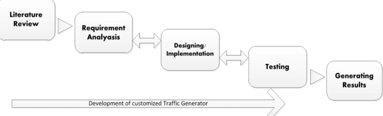
This chapter starts by presenting the methodology adopted in this thesis in order to fulfill the list of requirements presented in the last chapter systematically. To develop a system which fulfills our requirement, we need a proper plan and development model, based on which we can track the problems being encountered during the development process. We need to establish a traffic generator called SQgen to test QoS for VoIP applications in terms of signaling traffic. For this purpose I follow the modified water fall development model [5] for the process of development as shown in Figure 3. This figure shows the steps followed during the development of different modules of SQgen, these steps are elaborated in the following section.
Figure 3. Methodology for development of SQgen.
3.1 Literature Review
Prior to the development of SQgen, it was important to study VoIP architecture in detail including protocol stacks of SIP and H.323, SIP protocol, SIP servers and QoS concepts. SIP messages are studied and presented in detail, which provides a technical foundation for SIP Traffic Generator(presented in next chapter). After giving the detailed requirement specifications, a number of the existing state of the art traffic generators are reviewed in order to be re-used in this project.
3.2 Requirement Analysis
The four objectives presented in chapter 1 are analyzed and elaborated further in Section 2.5 Requirement Specification. It was also important to specify the list of requirements as a second step in the process of literature review to provide a reference point during survey of exiting traffic generators in Chapter 2.
3.3 Designing and Implementation
Based on the review of existing traffic generators, it was decided to develop our own traffic generator to realize our requirements. Three main modules are designed and implemented namely SQgen TCP/UDP module given in Figure 4, SIP Traffic Generator(STG) given in Figure 5, and Results Presentation Module given in Figure 8. All the modules are programmed in C language on Linux Ubuntu platform.
22
3.4 Testing
SIP Traffic Generator(STG) is used to do stress testing on OpenSIPS. Two test cases are used for testing, Test Case 1 and Test Case 2(refer to Chater 6 for more detail). In Test Case 1 the local network is in normal condition, there is no other bandwidth hungry application running. During Test Case 2, a portion of local network bandwidth is utilized by running Iperf client/server in order to see the effect on packet loss and delay.
3.5 Results Presentation
After the test cases are executed, a huge volume of data becomes available in the shape of Wireshark packet summary files. Another major contribution is to process these files effectively for results presentation, besides generating signaling traffic for SIP. The process and design of Results presentation module is discussed in detail in next chapter.
23
4. Design and Implementation of a customized traffic generator
The main design objective is to make a modular application where all tasks have independent modules. As shown in Figure 4, to generate TCP traffic a TCP module is defined, for UDP traffic a UDP module is defined and for SIP server overloading a separate module is defined. The purpose of modularity in this design is simplicity, re-usability, and especially it can further be very easily converted to a many-core application, where each module can be processed on separate core of CPU for high performance.
4.1 Design of SQgen
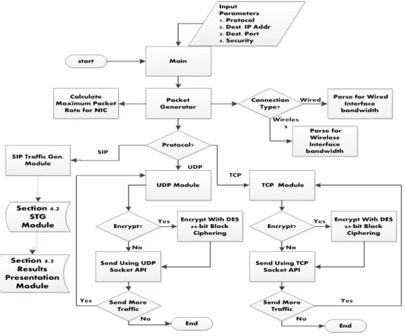
The diagram in Figure 4 shows the basic flow chart of SQgen. Main features of SQgen include: 1. Command-line parameter parsing for input different input parameters.
2. Evaluation NIC speed and maximum theoretical packet rate.
3. Sending UDP and TCP packets of different segment sizes with or without encryption.
4. Extended module for SIP traffic generation, for the purpose of simplicity we name it as SIP Traffic Generator Module or STG Module. Design and implementation of STG are discussed in Section 4.2.
5. Extended module for results presentation and analysis, this mode is named as Results Presentation Module or RPM. Design and implementation of this module are discussed in Section 4.3.
24 Figure 4 shows the design of SQgen for TCP and UDP traffic, on the receiving side accepts both the UDP and TCP packets simultaneously. Section 4.2 and 4.3 below give thorough description of SIP traffic generation, and results and analysis presentation modules.
4.2 SIP Traffic Generator(STG) Module
This module has been designed and developed to emulate a large number of SIP users in order to monitor and test the performance of OpenSIPS. This module has two sub-modules, namely, Sender and Receiver. The sequence of tasks performed by sender and receiver are depicted in Figure 5, followed by a brief description of both modules.
Figure 5. (Left) Block Diagram for SIP message exchange of sender and receiver with the SIP Serverk, (Right)SIP Session Overlaoding Module.
4.2.1 Sender
Sender generates n SIP sessions where n is the number of SIP users. This process followings the design given in the section 4 of RFC 3261, Session Initiation protocol and explained in chapter 2. The sender module registers n unique SIP users with OpenSIPS to establish n sessions by creating a Linux child-process for every user. In this way, the sender creates SIP users sequentially from user(1) to user(n).
4.2.2 Receiver
The receiver module follows the same process as the sender module does. The users created by sender module generate INVITE requests for the users generated by receiver module. Both sender and receiver must agree on the size of pool n, which denotes the number of SIP users/sessions to be created on the OpenSIPS. The sequence of user requests generated by receiver is typically from user(n+1) to user(2n).
25 In summary,
Sender Users: user(1), user (2), user(3),…,user(n)
Reciever Users: user(n+1), user(n+2), user(n+3),…,user(2n) For a 500 SIP sessions experiment,
Sender Users: user(1), user(2), user(3),…,user(500)
Reciever Users: user(501), user(502), user(503),…,user(1000)
User(1) sends INVITE to user(501), user(2) sends INVITE to user(502), user(3) sends INVITE to user(503)
and so on.
4.3 Results Presentation Module (RPM)
4.3.1 Time-stamping
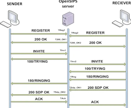
As discussed in section 2.3.2, OpenSIPS is the widely used open source implementation of SIP protocol and we have used it in our experiments for stress testing. The performance testing is based on processing delay of OpenSIPS, call set-up delay and sessions lost during a specific experiment. In order to calculate the processing delay and call set-up delay we need timestamps for different SIP messages processed on OpenSIPS. Figure 6 shows a typical SIP user registration and call set-up session and marks our desired timestamps for different SIP messages. Figure 6 is followed by a brief description of each timestamp. Sender and receiver modules can both initiate a SIP call, but the general convention in our experiment is that a SIP user on sender machine always initiates call to a SIP user on the receiver machine (Denoted by SIP INVITE message in Figure 6).
26 1. TReg1: Save the timestamp if the SIP message is a REGISTER request message from sender.
2. T200_OK1: Save the timestamp if the SIP message is a 200 OK, employing that the user registration requested by sender is successfully registered.
3. TReg2 and T200_OK2: Save the timestamps for REGISTER request/response timestamps for receiver in the same way as for sender.
4. TInv1: Save the timestamp if the SIP message is an INVITE request from a user on sender for a call set-up with a user on receiver.
5. TInv2: Save the timestamp if the SIP message is an INVITE response by OpenSIPS towards the receiver. 6. TRng: Save the timestamp if the SIP message is a 180 RINGING response from a SIP user on receiver to a
SIP user on sender.
7. TSdp_OK1: Save the timestamp if the SIP message is a 200 OK with SDP response from a SIP user on receiver who has already received INVITE from sender.
8. TSdp_OK2: Save the timestamp if the SIP message is a 200 OK with SDP response being forwarded to a SIP user on sender.
9. TAck: Save the timestamp if the SIP message is the acknowledgement ACK to the session description offered by receiver for the current SIP session in the SDP header.
4.3.2 Packet Capturing and Parameters for Parsing
While the SIP sessions are created by using the STG module, the traffic is being monitored by Wireshark [10] on sender, receiver and OpenSIPS machines. The captured output files from Wireshark are saved in seven lines packet summary text files. Each of these summary files is an input for RPM module. A typical Wireshark packet summary is given in Figure 7:
Figure 7. Wireshark Packet Summary.
A complete packet summary file may contain more than 10,000 Wireshark packet summaries for a 1,000 SIP sessions experiment. Appendix 3 gives a number of packet summaries to demonstrate how typical Wireshark packet summaries file looks like. The RPM module parses these packet summaries in the entire file for every packet captured and extracts the following parameters:
1. Time: This shows the timestamp when the packet was captured. 2. Source: This is the source IP address for SIP message.
3. Destination: Destination IP address for SIP message.
4. Protocol: Protocol can be either SIP or SDP depending on which SIP message is parsed. No. Time Source Destination Protocol Info
35 0.188134 192.168.1.2 192.168.1.4 SIP Status: 180 Ringing Frame 35 (577 bytes on wire, 577 bytes captured)
Ethernet II, Src: HonHaiPr_31:69:0b (00:1c:25:31:69:0b), Dst: HonHaiPr_cf:7b:54 (78:dd:08:cf:7b:54) Internet Protocol, Src: 192.168.1.2 (192.168.1.2), Dst: 192.168.1.4 (192.168.1.4)
27 5. Info: Info is the description of SIP message e-g. REGISTER, INVITE, 200 OK etc.
6. Src Port: UDP Source port 7. Dst Port: UDP Destination port.
RGM module parses the parameters listed above and manipulates them further to locate the timestamp for each SIP message. A brief stepwise description and block diagram of RPM is given the following section.
4.3.3 Pseudo Algorithm and Block Diagram
The packet summary files being captured while running the experiments contains a number of summaries of the type as given in Figure 7. Each of these files serves as input to the RPM module. Figure 8 gives the basic design of this module.
Figure 8. Block Diagram of Results Generation Module.
Following is a step-wise explanation of how the RGM module works:
Step1: Read File reads the Wireshark summary file and stores into a string buffer.
Step2: The string buffer from step1 serves as input to the Packet Parser. It extracts individual packet summaries and stores them into an array of structures named Packet[.]. This structure has seven strings variables for each line of the packet summary.
28 Step3: The Packets[.] entity servers as input to the Parameter Parser. Here the module parses all the desired parameters listed in section 4.3.2, from all the packet summaries contained in Wireshark output file, and saves them in an array of structures Param_List[.].
Step4: The Param_List[.] is further manipulated by Ports Parser to parse and save the sender and receiver UDP source and destination ports [11]. The source UDP port uniquely identifies each SIP user created by sender and receiver modules demonstrated in Figure 5. These ports are stored in Ports_Sender[.] and Ports_Reciever[.] arrays.
Step5: Timestamps Sender and Timestamps Reciever locate all of the timestamps related to the sender and receiver SIP users being processed on the OpenSIPS.
Step6: At last all the timestamps are stored in a text file in the format as given in Figure 9.
Figure 9. Output file of Results Generation Module.
In addition to the figure above, Appendix 3 gives a sample output file of Results Presentation module displaying timestamps for 100 SIP sessions.
Sender Sender Sender Sender Sender Sender Reciever Reciever Reciever Reciever REGISTER1 200 OK1 INVITE1 RINGING SDP OK2 ACK REGISTER2 200 OK2 INVITE2 SDP OK1 2,385794 2,386046 2,388812 2,572217 2,57327 2,579551 0 0,000633 2,395762 2,583655 2,386854 2,386999 2,390293 2,570922 2,571224 2,578424 0,001432 0,002014 2,389467 2,573132 2,38707 2,387214 2,390723 2,572426 2,572966 2,579105 0,00159 0,002088 2,396336 2,585449 2,387498 2,387638 2,391181 2,576948 2,577245 2,580265 0,003217 0,00385 2,393727 2,581026 2,387963 2,388099 2,391633 2,575299 2,576002 0 0,005368 0,005563 2,395715 2,578789 2,389103 2,389255 2,393417 2,580292 2,581152 2,584336 0,005523 0,005666 2,392042 2,575882
29
5. Experimental Set-up
This chapter gives an overview of test set-up including software and hardware tools used to establish this set-up. The purpose of this set-up is to investigate the performance of OpenSIPS in a LAN environment where the OpenSIPS is used as registrar and proxy server. The server is run on a standalone PC in the network waiting for SIP requests to serve. Sender and Receiver modules of STG module first generate requests to register SIP users on server and then send requests to establish call sessions for these users(explained in Chapter 4, Section 4.2) . Ordinary PC hardware is used in this set-up, so we cannot make sure that the server overloads due processing bottleneck of CPU and NICs. However, the results can be used for comparative analysis in different test scenarios.
The results analysis is based on two test scenarios. First scenario represents ideal condition where the network resources are totally available the test set-up, it will help us evaluate the delay and packet loss different SIP events. In the second scenario the network bandwidth is artificially utilized by sending a significant amount of data between two other dedicated PCs. This happens the entire period of time during the second scenario to simulate a real network case, where data communication happens for different applications at the same time. Section 5.1 below demonstrates these test scenarios, followed by section 5.2 for system specification of the hardware being used.
5.1 Test Scenarios
The stress testing has been performed on the basis of two network scenarios. In the Scenario 1 a local network is established connecting Sender, Receiver and OpenSIPS PCs as depicted in Figure 10. The network status is idle and full capacity can be utilized during experiments in Scenario 1. OpenSIPS is configured on the server PC, Sender module (section 4.2.1) is run on Sender PC and receiver module (section 4.2.2) is running on Receiver PC. Wireshark monitors the traffic on all the PCs and the output files from Wireshark are saved for each experiment.
30 In Scenario 2 we partially utilized the local network bandwidth by sending UDP traffic between two other dedicated stations before running the SIP Traffic Generator. This will help us present a case where the network is busy or peak hour situation, and we expect that the delays for SIP message processing on the server and the packet loss will increase by doing so. The results generated using this scenario can be used to investigate the difference/increase in lost SIP sessions and registration requests by the server. In this scenario the same underlying network and hardware/software components are used. In addition, two more PCs are connected to the network called Iperf Client and Server. As described in section 2.6.7, Iperf is used by these two PCs to partial utilize the network resources. Figure 11 demonstrates the network topology for Scenario 2.
Figure 11. Test Set-up for Overloading OpenSIPS Scenario 2.
5.2 System specifications
The sender and receiver PCs uses Wi-Fi 802.11 b/g/n connection to the LAN router, and the server PC uses a 100 Mbps wired connection to the same device. Internet connectivity is also enabled during testing process to take into considerations the constraints imposed by real-time communication. Table 2 gives technical specification of PCs and router used in network set-up.
Wi-Fi connectivity is the mainstream method of connectivity for individual and commercial use in modern computer communications; it is utilized by the SIP sender and receiver to realize different factors induced by wireless communications (these factors are further discussed in Results section of Chapter 6)
31
Table 2 Systems Specification for Experimental Set-up
OpenSIPS Server PC
1 Number of cores 2
2 CPU Intel(R) Pentium(R) Dual CPU E2140
3 Speed 1.60GHz
4 Memory(RAM) 2GB
5 Memory (cache) 1 MB per core
6 System Architecture 32 bits
7 Operating System Ubuntu version 10.04LTS
8 Network Card Fast Ethernet 100 Mbps Realtek RTL8139
Sender PC
1 Number of cores 22 CPU Intel (R) core(TM) i3CPU M330
3 Speed 2.13 GHz
4 Memory(RAM) 4 GB
5 Memory (cache) 3MB per core
6 System Architecture 64-bits
7 Operating System Ubuntu version 10.04LTS
8 Network Card 802.11 b/g/n MAX 150 Mbps
Receiver PC
1 Number of cores 22 CPU Intel(R) Core(TM) Duo CPU
3 Speed 2.60GHz
4 Memory(RAM) 3GB
5 Memory (cache) 3MB per core
6 System Architecture 32 bits
7 Operating System Ubuntu version 10.04LTS
8 Network Card 802.11 b/g
Wireless / LAN Router
1 NETGEAR N300 Wireless Router
2 Network Type Operating Mode Wireless F. Band Wireless: 802.11 b/g/n Wired: 100 Mbps, 100BASE-Tx 145 Mbps 2.4 GHz
32
6. Experimental Evaluation
Based on the test scenarios demonstrated in previous chapter, a series of tests/experiments are performed in this project. In Section 6.1, we discuss test case in each scenarios and the number of tests performed in each test case. Section 6.2 discusses the results of Test Case Scenarios for different SIP operations on being performed on OpenSIPS.
6.1 Test Cases
As discussed in Chapter 5, there are two categories of tests performed in this thesis, namely Test Scenario 1 and Test Scenario 2. In Scenario 1 we perform the experiments to register a number of SIP users and generate SIP sessions for these users according to the test set-up given in Figure 10, and Scenario 2 follows test set-up of Figure 11. Further, there are a number of Test Cases in each scenario where each test case represents the number of SIP sessions created during the test. For each test case a number of tests are performed to reduce the chances of data anomalies in the results.
6.1.1 Test Cases in Scenario 1
In this scenario we try to overload the OpenSIPS server through a series of test cases, by measuring delay for SIP messages and packet loss during each test. The process of how to measure delay and packet is discussed in detail in Section 4.2 and 4.3 of Chapter 4 . There are a total of 8 test cases, where 5 tests are performed in each case. The number of SIP Sessions increases from 10 in test case 1 to 1,000 in test case 8 as depicted in Table 3 below:
Table 3 Scenario 1 Test Descriptions Test
Case No. SIP Sessions Number of Number of tests
1 10 5 2 100 5 3 200 5 4 400 5 5 500 5 6 600 5 7 800 5 8 1000 5
6.1.2 Test Case Scenario 2
As described in Section 5.1, in Scenario 2 we partially utilize the local network resources to see the effect on packet loss and delay for SIP messages. The local network is overloaded using Iperf (a network performance measurement tool, see more description in section 2.6.7). The network is loaded with 50 Mbps out of 100 Mbps network capacity in the each Test Case and the test is repeated again by loading the network with 75 Mbps. The overview of tests performed is given in Table 4:
33
Table 4 Scenario 2 Test Descriptions
Test
Case No. Number of SIP Sessions Network Overload 50 % Number of tests Network Overload 75 % Number of tests
1 10 1 1 2 100 1 1 3 200 1 1 4 400 1 1 5 500 1 1 6 600 1 1 7 800 1 1 8 1000 1 1
6.2 Results
The process of monitoring the traffic on server and generating the Wireshark packet summary files is explained in Section 4.3 of Chapter 4. After these files are processed by Results Presentation Module, the generated data is further processed in spreadsheets to generate graphs for delay of different SIP operations and packet.
6.2.1 Delay and Packet Loss Specification
A typical SIP session consists of a number SIP messages as shown in Figure 2 of section 2.2. To make an analysis based on delay and packet loss, we define different parameters in this Section for graphical representation of results.
1. Delay for User Registration on OpenSIPS
This delay is the time interval when the REGISTER request is received by server and 200 OK is sent by server. Thus, it is the time taken by SIP server to successfully register a SIP user. If registration is unsuccessful or the request is not received by server, it is marked as a lost session.
2. Delay for INIVTE Processing on OpenSIPS
This delay is the time interval when an INVITE request is received by server and it is routed by the server to the designation SIP user. OpenSIPS can be configured as SIP router at multiple locations to route VoIP calls between distant network locations. However, in this thesis only a single OpenSIPS server is used between sender and receiver in a LAN environment, because the scope of the project is to evaluate the performance of a single SIP server.
3. Call Set-up Delay
Call set-up delay is the time interval when the INVITE is received by server till ACK is received from the requesting SIP user. By sending ACK message, receiver acknowledges the session description parameters of the sender, which are sent in in 200 SDP OK responses. The Call set-up delay also takes into account the communication delay between SIP users and the processing delay imposed by these users.
Figure 12 shows all the delays identified above and the corresponding timestamps for the related SIP messages.
34
Figure 12. REGISTER, INVITE and Call Set-up Delays.
4. Lost Sessions and Packet Loss
A packet carrying SIP request/response message can be lost during communication. In SIP message exchange process, the packet loss comprises to lost sessions. If any of REGISTER, 200 OK, INVITE, 180 RINGING, 200 SDP OK and/or ACK message does not reach its destination, it is marked as a lost session. Following section presents graphical results and explanation for the above specifications for both scenarios. In this way there are a total of 8 graphs presented in in 8 sub-sections. These graphs give comparative analysis of average, minimum and maximum values of the above listed SIP operations.
6.2.2 REGISTER Delay Scenario 1
In Figure 13, as the number of user registration sessions increases step-wise from 10 to 1000, the maximum delay for processing for these sessions do not increase smoothly. We can see that the MAX delay for 10 users is higher than delay for 100 user sessions at the start of x-axis. The potential reasons may include processing burden of Wireshark and MySQL, the server is also connected to Internet (which might have imposed delay at this stage due to traffic flow of other applications).
Figure 13. User Registration Delay chart for Scenario1.
10 100 200 400 500 600 800 1000 REGISTER MIN 0,000122 0,000072 0,000087 0,000073 0,000072 0,000068 0,000075 0,000082 REGISTER AVG 0,000840 0,000780 0,000260 0,000234 0,000675 0,000364 0,000446 0,000347 REGISTER MAX 0,006809 0,000964 0,005611 0,005878 0,017411 0,017532 0,009259 0,015377 0,000 0,002 0,004 0,006 0,008 0,010 0,012 0,014 0,016 0,018 0,020 Ti m e in Sec on ds
No. of SIP Users
35 Figure 13 indicates that MAX delay is 17.5ms and it decreases as the number of sessions increase to 800 and 1000. The reason for this is the increase in lost REGISTER sessions as indicated in Figure 19 of section 6.2.8. For 600 users lost sessions are only 129 but for 800 and 100 they jump to 568 and 1577 respectively. In conclusion, this graph shows that the server is stressed if the number of registration requests increases more than 600. The AVG delay ranges from 0.23ms to 0.84ms, and MIN delay from 0.06ms to 0.12ms.
6.2.3 REGISTER Delay Scenario 2
In Scenario 2 the local network is partially loaded by injecting UPD traffic, which has shown a significant effect on the performance of OpenSIPS. As we can observe in Figure 14, the MAX REGISTER delay reduces to approx. 11ms as compared to 17.5ms in Scenario 1. Since the network switching element has got much traffic to forward, the speed at which the SIP traffic is forwarded is also reduced. The network delay has risen and the packet loss has also been reduced from 129 to 44 (Figure 20) for 600 REGISTERs (and in the same fashion for other test cases). The lossy network behavior observed here has many potential reasons for packet loss. Section 6.3 describes and investigates possible reasons for packet loss during these experiments.
Figure 14.User Registration Delay chart for Scenario 2.
The average delay ranges from 0.16ms to approx. 1ms. It is only in 100 users experiment when the AVG delay is 1ms; otherwise, the MAX averaged delay is approx. 0.6ms. So, there is a significant decrease in registration delay as compared to Scenario 1. There is no drop in MIN delay; it is still from 0.06ms to 0.14ms. 10 100 200 400 500 600 800 1000 Register MIN 0,000136 0,000099 0,000089 0,000084 0,000074 0,000079 0,000080 0,000063 Register AVG 0,000219 0,001035 0,000173 0,000621 0,000169 0,000585 0,000312 0,000422 Register MAX 0,000435 0,001418 0,000974 0,010988 0,001188 0,008825 0,007425 0,010454 0,000 0,002 0,004 0,006 0,008 0,010 0,012 Ti m e in Sec on ds
No. of SIP users
36
6.2.4 INVITE Delay Scenario 1
As we see in the Figure 15, the MIN delay for an INVITE is 0.03ms as compared to 0.06ms for REGISTER. We can also observe that the AVG and MAX delays increase significantly after the number of session increases more than 600. There is also a drop in the MAX delay for 800 sessions, and reason for this is the packet loss, which is more than double as compared to 600 sessions. Before 600 sessions the increase in lost sessions is somewhat uniform as indicated in Figure 19. MAX delay increases again for 1000 sessions to 1.7 seconds since the packet loss is not as high as compared to the jump 600 to 800 sessions. The AVG delay ranges from 2ms for 10 sessions to 492ms for 1000 sessions, and MIN delay ranges from 0.03ms to approx. 0.1ms.
Figure 15.INVITE Delay chart for Scenario 1.
6.2.5 INVITE Delay Scenario 2
Figure 16 shows delays for INVITE processing on OpenSIPS for Scenario 2. Compared to Scenario 1, maximum AVG delay has decreased from 492ms to 379ms while the maximum MAX delay has decreased from 1.7 seconds to 1.5 seconds. There is no significant change in the MIN delay and ranges from 0.06ms to 0.2ms, with an exception at 10 sessions where it is 0.8ms. It is also clear that the server becomes overloaded as the user sessions increases more than 600, with an unexpected increase in the MAX delay for 200 user sessions. There seems to be no clear reason but we can observe in Figure 20 that the packet loss for 200 user sessions in not increased as compared to 100, but it has significantly increased for 400. 10 100 200 400 500 600 800 1000 INVITE MIN 0,000048 0,000045 0,000036 0,000088 0,000051 0,000099 0,000026 0,000059 INVITE AVG 0,002484 0,013442 0,057887 0,154533 0,209903 0,290815 0,249195 0,492151 INVITE MAX 0,007756 0,175650 0,619345 0,949625 1,380765 1,537362 0,896963 1,772708 0,0 0,2 0,4 0,6 0,8 1,0 1,2 1,4 1,6 1,8 2,0 Ti m e in Sec on ds
37
Figure 16.INVITE Delay chart for Scenario 2.
6.2.6 Call Setup Delay Scenario 1
Figure 2 show delays for successful SIP sessions which comprises to VoIP call set-up time. The MIN delay ranges from 22ms to 258ms, AVG delay ranges from 77ms to 722ms, and MAX delay ranges from 216ms to 3.9 seconds. The delay 3.9 seconds looks unexpected for 200 user sessions, and 2.3 seconds is the next highest MAX delay for call set-up for 400 users. There can be many potential reasons for this unexpected behavior including operating system interrupts from other applications, network congestion etc. As the sessions increases from 200 to 400, the MAX delay and packet loss decreases significantly. So, it seems that the server is overloaded during this shift, but it might not be the case. If we closely look at the AVG delay, it very smoothly increases from 100 until 1000 sessions. Since, Call set-up includes the communication and processing delays between sender-server and server-receiver as well. In conclusion, we cannot predict that server overloading from this scenario as it has many dependencies on other factors.
Figure 17. Call Set-up Delay chart for Scenario 1.
10 100 200 400 500 600 800 1000 Invite MIN 0,000826 0,000065 0,000178 0,000101 0,000072 0,000099 0,000275 0,000151 Invite AVG 0,004012 0,036184 0,315691 0,319113 0,314779 0,379148 0,303157 0,273194 Invite MAX 0,007297 0,144887 0,817744 0,681610 0,642155 0,816839 0,879740 1,552600 0,0 0,2 0,4 0,6 0,8 1,0 1,2 1,4 1,6 1,8 Ti m e in Sec on ds
No. of SIP Users
MIN MAX and AVG INVITE Processing Delay
10 100 200 400 500 600 800 1000
Call set-up MIN 0,022475 0,041759 0,063466 0,093131 0,068082 0,056388 0,100604 0,258641 Call Set-up AVG 0,077420 0,091928 0,285559 0,439003 0,589581 0,645185 0,643641 0,722673 Call Set-up MAX 0,216975 0,444698 3,930359 2,382014 1,861707 1,491779 1,417823 1,446756
0,0 0,5 1,0 1,5 2,0 2,5 3,0 3,5 4,0 4,5 Ti m e in Sec on ds
No. of SIP Users