Concept for Improvement of
Afterload in an Ex Vivo Heart
Evaluation System
Ludvig Sj¨
oberg
Mechanical and Materials Engineering Bachelor
15 credits 2018
Supervisor: Ulf Hejman (Malm¨o University)
Abstract
Today there are waiting lists for people in need of a heart through trans-plantation and every year people in these lists die due to deficiency of donated, transplantable hearts. Many of the hearts donated are dis-carded due to uncertainty regarding their condition, such hearts are called marginal hearts. The high number of marginal hearts have led Igel¨osa Life Science AB to develop a system for evaluating the actual performance of a donated heart ex vivo with the aim to prove transplantability of otherwise marginal hearts. The heart evaluation procedure is done in a stand-alone device prior to the implantation, and is to create proof of a donated heart’s compatibility with the recipient. The proof comes mainly from the heart’s ability to produce blood pressure.
To simulate the arterial blood flow resistance, a component called af-terload has been developed as a part of the heart evaluation system. It is connected to the outlets of an ex vivo heart. The aim with the heart evaluation procedure is to verify that the donated heart is in a sufficiently good condition to create blood pressure and flow in the recipient’s body. The purpose of this work is to increase the number of donated hearts transplanted by improving the usability of the heart evaluation system. This work is focused on the afterload and aims to solve problems identified during experimental use, such as controllability of the flow resistance and making it controllable from outside the sterile field in which it operates.
The work results in a concept for an afterload that controls the flow resistance by an adjustable volume which is mounted outside the sterile field. Further development of this concept might include component selec-tion for the control system for the flow resistance and design of pressure relief that might be necessary.
Sammanfattning
Hj¨artevaluering ¨ar avsett f¨or att ¨oka antalet transplanterade donerade hj¨artan med m˚alet att bli standardbehandling i samband med hj¨ arttrans-plantation. Anledningen till behovet av hj¨artevaluering ¨ar att samtidigt som m¨anniskor d¨or i v¨antan p˚a ett nytt hj¨arta s˚a kasseras donerade hj¨artan p˚a grund av os¨akerhet kring deras f¨orm˚aga att skapa tillr¨ackligt blodtryck och -fl¨ode i mottagarens kropp.
Detta arbete behandlar utveckling av koncept av en komponent i ett hj¨artevalueringssystem som utvecklas av Igel¨osa Life Science AB. Kom-ponenten ¨ar ett fl¨odesmotst˚and som kallas afterload och som anv¨ands f¨or att utv¨ardera ett donerat hj¨artas f¨orm˚aga att skapa blodtryck.
Syftet med detta arbete ¨ar att f¨orb¨attra anv¨andbarheten av hj¨ art-evalueringssystemet f¨or att ¨oka antalet transplanterade hj¨artan och p˚a s˚a vis r¨adda liv. M˚alet ¨ar att ta fram ett koncept f¨or en afterload som har po-tential att l¨osa problem som identifierats under experimentella k¨orningar av systemet. De huvudsakliga problemen ¨ar att en tillr¨acklig skillnad mellan det diastoliska och systoliska trycket inte kan uppn˚as samt och att afterloaden kr¨aver en sterilkl¨add person f¨or att styras.
Arbetet resulterar i ett koncept som fr˚an utanf¨or det sterila f¨altet som afterloaden verkar i kan styra fl¨odesmotst˚andet och skapa fl¨odesmotst˚and som ¨ar tillr¨ackligt f¨or att utf¨ora hj¨artevaluering. F¨orslag p˚a framtida arbete ¨ar att vidareutveckla konceptet genom att unders¨oka behov av ¨
overtrycksskydd i styrsystemet f¨or fl¨odesmotst˚andet samt att g¨ora komp-onent- och materialval.
Preface and Acknowledgements
This is a Bachelor thesis in the field of mechanical and materials engineering. The writer of this work is a Mechanical and Materials Engineering student at
Malm¨o University. I take this opportunity to express gratitude to my two
super-visors Ulf Hejman at Malm¨o University and Stig Steen at Igel¨osa Life Science
AB. By giving me their time, support and guidance I’ve managed to produce a work that I’m proud of. I am also grateful to my partner who supported me all the way through this venture.
Ludvig Sj¨oberg
Contents
1 Introduction 1
2 The Anatomy of the Heart 2
3 Characteristic Properties of Medical Devices 3
4 Ex Vivo Heart Evaluation 4
5 The Afterload 5
6 Design Methodology 8
6.1 Identification of Customer Needs . . . 10
6.2 Properties and Specifications . . . 12
6.3 Concept Generation . . . 14
6.4 Concept Selection . . . 16
6.5 Concept Development and Modeling . . . 17
7 Real Gas Modeling 17 8 Development of Afterload Concept 18 8.1 Problem Definition and Identification of Needs . . . 18
8.1.1 Analysis of Needs . . . 20
8.2 Product Specification . . . 23
8.3 Concept Generation and Selection . . . 25
8.3.1 Identification of Critical Subproblems . . . 27
8.3.2 Generation of Concepts . . . 27 8.3.3 Concept A . . . 28 8.3.4 Concept B . . . 28 8.3.5 Concept C . . . 28 8.3.6 Concept D . . . 29 8.3.7 Concept E . . . 29 8.3.8 Concept F . . . 29 8.4 Concept Selection . . . 29
9 Development of Selected Concept 29 9.1 3D CAD Modeling . . . 32
11 Conclusion 36
References 37
Appendix A Interviews Appendix B Backlogs
Appendix C Product Specification Appendix D Concept Sketches
1
Introduction
Today there are waiting lists for people in need of a heart through transplan-tation and every year people in these lists die due to deficiency of donated, transplantable hearts. Many of the hearts donated are discarded due to uncer-tainty regarding their condition. Such hearts are called marginal hearts.
The length of time that a heart is outside the body between explant and implant today is usually four hours [1]. During that time the heart is ischemic (insufficient blood circulation through the heart causing insufficient oxygenation and nutrition of tissue)[2] and is kept on ice to keep the temperature down. The short time frame of four hours makes coordination and infrastructure crucial for a successful outcome. A new method that enables a heart to be outside a human body for up to 24 hours has recently been published [3]. With a time frame of 24 hours instead of four, there is time to perform evaluation of the heart before implanting it.
The heart evaluation system under development by Igel¨osa Life Science AB
[4] (Igel¨osa) consists of two closed loop circuits comprising the two main blood
circuits in the human body: lungs and body. The heart is mainly evaluated by its ability to produce blood pressure and the evaluation is done by producing flow resistance on the heart outlets. The component for producing flow resistance is called an afterload and it is mounted on the heart outlets: pulmonary artery that conducts oxygen poor blood to the lungs and the aorta that conducts oxygen rich blood to the heart itself and the rest of the body. By being able to adjust the flow resistance through the afterloads, it’s possible to evaluate what pressures can be produced by the heart. Since a heart during explantation is ischemic (no blood circulation, i.e. not beating) and the heart must be beating to produce blood pressure, the heart is taken out of its ischemic state once it has been set up in the evaluation system.
The purpose of this work is to improve the usability of the heart evaluation system to increase the number of donated hearts to be transplanted and thereby increase the number of lives saved. This work is focused on improvement of the afterload design and the main problems that it aims to solve are that the afterload with its current design cannot be computer controlled, the diastolic and systolic pressures aren’t independent, and the afterload is controlled in the sterile field by a person who in a clinical setting isn’t sterile. The scope of this work includes preparing a product specification, generating concepts, selecting the most suitable concept and making a graphic representation of the selected
concept using 3D CAD software.
The scope of this work is delimited by not taking explicit consideration of sterilizability or manufacturability. Neither are prototypes to be built. Since the focus of this work is placed on physics and mechanics for controlling the afterload, improvements of aspects such as anatomical or biological are beyond the scope.
2
The Anatomy of the Heart
The human heart resembles two pumps that pumps blood through two circu-latory systems: the pulmonary and the systemic, see figure 1. The pulmonary system is delimited by the right heart side outlet (right ventricle) and the left heart side inlet (left atrium) and passes through the lungs for oxygenation. The systemic circulation system is delimited by the left heart side outlet (left ven-tricle) and the right heart side inlet (right atrium) and circulates blood through the body.
The heart pumps blood through the two circulatory systems by relaxing to
allow blood to flow into its chambers and then contracting to push the blood out into the vessels. To circulate blood through the body, a pressure higher than the one for the pulmonary system must be produced which makes the left heart side muscles both larger and stronger than the right heart side on a healthy human. [6]
The two most important blood pressures that a heart produces to create blood circulation in the lungs and body are the diastolic and the systolic pres-sures and are different in the two circulatory systems. The diastolic pressure occurs during diastole which is the state in which the heart is relaxed, and the systolic pressure occurs during systole which is the state in which the heart is contracted. These two pressures are caused by the resistances of the circulatory systems. Normal systemic blood pressures at rest are a systolic pressure of 120 mmHg and a diastolic pressure of 80 mmHg. The normal maximum systolic pressure produced by the left ventricle is 250-300 mmHg and the right ventricle 60-80 mmHg. A normal stroke volume (blood volume per heart beat) for a grown up human is 70 mL at rest.
Another crucial difference between the two sides of the heart is that the blood supply to the heart itself comes from the aorta via the left ventricle. During diastole and due to the diastolic pressure, the blood flows through the coronary artery and empties into the right atrium. The blood flow through the coronary artery feeds the heart tissue with oxygen and nutrition. In contrast to diastole, almost no blood flows through the coronary artery during systole due to the high pressure in the heart wall caused by the muscular contraction. [6]
The systolic and diastolic blood pressures are interrelated in the human body [7] and the difference between them is called the pulse pressure. Pulse pressure (Ppulse) is defined as the difference between the systolic and diastolic pressure
(Psystolic and Pdiastolic) according to (2.1). The pulse pressure is interesting
because it is not constant, and to be able to do a heart evaluation, the equipment must be able to produce different pulse pressures.
Ppulse = Psystolic− Pdiastolic (2.1)
3
Characteristic Properties of Medical Devices
Medical device is a term for a product intended for use within health and medical care. It covers any products from plasters to pacemakers and stands under market surveillance of The Swedish Medical Products Agency and is covered by
the law on medical devices. [8]
Within the field of medical devices, some product properties are given more importance than in other fields of engineering. Such are sterility, cleanliness and bio-compatibility.
Sterility and cleanliness is not the same thing [9]. Sterility is defined as the absence of microbial life and cleanliness as the absence of soil and/or particles of a predetermined size. Sterilizing single-use medical devices usually requires advanced technology and highly regulated processes while sufficient cleaning can be achieved by wiping with water or alcohol. The design of a component can be more or less suitable for sterilization and depends mainly on two things: geometry and material. Geometry-dependence is due to the criticality of all surfaces being exposed to the sterilization medium. The material-dependence is due to the fact that the sterilization process might have a adverse effect on the material. Sterilization processes using high temperature might not be compatible with polymer materials for example [10].
Bio-compatibility is defined as the ability to be in contact with a living system without creating adverse effect [11]. Medical devices in direct contact with living systems such as human organs or blood shall be bio-compatible.
4
Ex Vivo Heart Evaluation
Ex vivo heart evaluation is done because the health status of an explanted heart is unknown. What is known is that the ischemic time of a heart correlates with the donor survivability. By being able to evaluate a heart ex vivo in a nonis-chemic state, i.e. beating outside a human body, the real performance of the heart can be evaluated and recipient arterial system compatibility verified. The heart donated by a healthy young man can for example be too weak to pump blood through the pulmonary system of a small woman if she has pulmonary hy-pertension [12]. In an unhealthy human the resistance in the pulmonary system can be equally as great as in the systemic, i.e. the right heart side has grown to be as large and strong as the left. Risk factors for pulmonary hypertension are, among other things, overweight, chronic obstructive lung disease (COPD) and street drugs such as cocaine [13].
The springboard for heart evaluation is in the Langendorff model, invented in 1895 by Oscar Langendorff. The Langendorff model allows for ex vivo medical treatment of a heart by retrograd perfusion. This perfusion is performed by
creating a pressure in the aorta that closes the aortic valve and allows the pressurized perfusate to flow through the coronary artery during diastole, see chapter 2. The blood is supplied ”backwards” into the aorta. This way the heart muscle can be fed with nutrients and oxygen to be able to beat for several hours outside the body. [14]
In 1971 Nicolaas Westerhof published an article with the title ”Artifical ar-terial system for pumping hearts” [15] which describes a model for evaluating the pressure that a heart can produce ex vivo. The model is based upon letting the cardiac output flow through small tubes and together with a compliance produce a model of the human arterial system. The components can be analo-gized with electronic components: two resistors and a capacitor. Years later a component that corresponds with an inductor is added to the model [16]. The theoretical behavior and outcome from this model is what is used in the heart evaluation system that this work is about.
Until today researchers have been using the Langendorff model among oth-ers to do ex vivo heart perfusion and evaluation research [17]. With the new method for heart perfusion described in the introduction though, a new world of possibilities for ex vivo heart evaluation will open up and the future of heart transplants might include ex vivo heart evaluation as a standard operating pro-cedure thanks to the extended time a heart can be outside a human body.
5
The Afterload
A prototype of the heart evaluation system has been developed and tested non-clinically. During experiment runs with the system, the performance of the afterload has not been satisfying and is subject for improvement.
Due to the difference between diastolic and systolic pressure, the resistance of the afterload is designed to be dynamic. It can be described analogous with an air suspension system of a car: A certain pressure is produced by a compressor to hold the vehicle in level and the setting of a relief valve determines the maximum pressure that is allowed by driving over an unleveled manhole at high speed. The level pressure is analogous with the diastolic pressure and the impact from the unleveled manhole is analogous with the cardiac output. The current solution is patented [18]. The compressor in the car analogy is item 46 in figures 2 and 3 and the relief valve is item 40 in the same figures. Item 36 is a reservoir which creates a kind of flexibility or elasticity towards a structural
changed pressure in the system and this flexibility is called compliance within the field of physiology [6].
Figure 2: Illustration from patent for heart evaluation device [18] illustrating a heart with afterloads connected to the aorta and the pulmonary artery re-spectively. RA=right atrium, RV =right ventricle, LA=left atrium, LV =left ventricle.
Figure 3: Illustration of afterload and compliance from figure 2 [18]. An illustration submitted in the patent for the heart evaluation system, see figure 4, shows the sequence of states over the period of a heart beat. When the heart ejects a volume of blood, the blood flows into the afterload inside which an inflated balloon is mounted. Depending on the pressure of the balloon, the balloon collapses and lets the blood pass through. When the volume of blood has passed through the afterload, the balloon reinflates. If the heart cannot produce blood pressure to overcome the balloon pressure and collapse it, the
Figure 4: Illustration of the afterload in cross section view [18]. The afterloads labeled Fig. 3a-d illustrates the assumed behavior of the balloon in different states of the heart beat. The heart outlet is connected to the left side of the afterload. Fig. 3b illustrates systole which generates the highest pressure. This will cause the afterload balloon to collapse and therefore compliance pressure to rise (compliance medium flows out from balloon).
heart might take serious damage. This risk is mitigated by safety systems built into the heart evaluating system.
A heart’s ability to produce blood pressure is evaluated by its ability to create enough blood pressure to collapse the balloon and create flow through it. By increasing the balloon pressure, the heart’s ability to produce a predetermined blood pressure is verified. The pressure that the heart will be evaluated for is related to the blood pressure of the recipient.
an adjustable narrowing in the pneumatic system of the afterload. When the cardiac output flows through the afterload and compresses the balloon, the medium in the balloon is pushed through the narrowing and a pressure greater than the diastolic pressure is achieved due to the decreased balloon volume and the resistance in the narrowing. A more open narrowing causes less resistance and thereby a lower systolic pressure. The diastolic pressure is automatically regulated and kept constant at the set value by a pump, item 46, and a reservoir, item 36, is used to create compliance (elasticity) in the system.
The afterload in its current embodiment is due to the fact that it has been used in multiple non-clinical experiments, functioning well in many aspects. It it able to simulate the vascular resistance in a human body to evaluate a heart’s ability to produce blood pressure built with simple design and few components. Through interviews with people experienced with the concept it becomes apparent that several problems with the current design exists however. The most critical ones are identified as only a few: The current design allows for testing the concept of heart evaluation, but within a limited range of pressures. When the diastolic pressure is at 80 mmHg, a systolic pressure greater than 140 mmHg cannot be achieved. One possible reason is thought to be the design of the knob and the shape of the narrowing for adjusting the resistance through the narrowing.
Other critical problems are that to control the systolic pressure, a person needs to physically interact with the afterload inside the sterile field, and this interaction is in clinic done by a person who is normally not sterile gowned (a perfusionist).
Figure 5 depicts the connection to the afterload (hose barb). Inside the ver-tical cylinder that the barb connects to is the one-way valve, item 38, mounted. The half moon shape is the current design of the narrowing, item 40, which is more or less covered by a knob (not in picture).
6
Design Methodology
Design methodology is a sub-discipline of the field of engineering and it is a tool for achieving repeatable results and ensuring that the design of products are suitable for their intended use [19]. The design methodology in this work is
based upon Produktutveckling : Effektiva metoder f¨or konstruktion och design
Figure 5: Current design of the part of the afterload that this work focuses on. The knob (not in picture) adjusts the coverage of the half moon shaped narrowing to control the flow resistance through it.
Ulrich and Eppinger [21]. Unlike design methodologies that focuses on bringing commercially successful products to market, these two books have been selected due to their focus on breaking down complex problems which is suitable for the development of technical products.
Generally the design methodology for product development can in many cases be divided into five steps: 1. product specification, 2. concept generation, 3. evaluation and concept selection, 4. detail design and planning, 5. man-ufacturability adaptation [20, 21]. The first, second and third of these steps are within the scope of this work. The method used in this work consists of handpicked activities from multiple sources of design methodology.
The product specification part is the first step in the process. It consists of project planning, identification of needs, identification of properties. The outcome is a goal specification for the product.
The planning work is done by the organization that owns the development project and is beyond the scope of this work. It comprises activities such as feasibility studies of different ideas and decision making on what ideas to go ahead with. An idea can be anything from simple improvements of existing products to ground research in new fields of science, much depending on the strategy that the organization has chosen as its business focus. The outcome of the planning work is a design brief that describes the product and prod-uct advantages including assumptions and limitations, market goals and target
market.
With the design brief at hand, the procedure of identifying and defining the customer (user) needs begins. This is crucial to ensure that the outcome of the project is suitable for its intended use.
The identification of customer needs is done by collecting data from holders. For a product that currently has no equivalence on the market, stake-holders can be for example experts in the field or market in which the product is intended for, the inventor(s) of the idea or other people with relevant knowledge. The next step in the product specification process is to identify what prop-erties the product can have to fulfill the needs that have been identified. These specifications are technical and measurable to make the result of the project verifiable. With the properties defined, a goal specification is created. The goal specification is a draft and it is changed as new knowledge emerge during the course of the project.
In agile development, a design method often used in software development projects, a backlog is a document containing work to be done within the project, but later on [22]. A backlog can also be used as a repository for work to be done later, but not within the project that the idea for the work came up. This is a global backlog for the development of a whole system.
Prior to commencing in the concept development, the scope of the work is agreed upon between the supervisor or project owner and the development team. Information that is beyond the scope but still might be of interest in future work can be stored in the global backlog.
6.1
Identification of Customer Needs
A customer is defined as a stakeholder in the project, for example an end user or the inventor of the system in which the product is a part. Stakeholders usually have put something at stake for the project to succeed, for example money or reputation. Quality is measured by how well a product fulfills the needs of a customer. It is therefore crucial that the identification of customer needs are conforming to the actual needs of a customer.
The five aims of the process for identification of customer needs and creating the mission statement are high level aims (keyword is why). The first aim is to ensure that the product is focusing on the customer needs. A product is not better than it is satisfying the needs of the customer and this is also how quality can be defined and measured. Secondly the process should identify latent
and hidden (implicit) needs and translate them into explicit ones. Latent and hidden needs are for example needs that the customer takes for granted that the product will satisfy or that the needs are subconscious in the way that they haven’t been expressed explicitly yet [21]. Thirdly the mission statement is, as described above, the foundation on which the product specification is built upon. A product property that cannot be anchored in an implicit or explicit need should, ideally, not be paid for by the development project owner or the market. The fourth aim is to ensure that no crucial customer needs are overlooked and forgotten. As with the third aim, if the product specification doesn’t include properties for satisfying all customer needs, especially the required ones, the product might render useless. A product is always only one property away from being useless within the intended area of use (e.g. airplane without property of flight). The fifth and last aim of the process of identifying customer needs is to increase the understanding of the customer needs within the development team. To create and maintain leverage, all team members must have the same perception of what is to be the foundation of their work activities. [20, 21]
The identification of customer needs begins with collecting information from stakeholders. The main source for this kind of information for a project with high level of novelty is from interviews with stakeholders. Literature is another source of information. Interviews are performed between four eyes to prevent negative influential phenomenas such as group pressure or withholding opinions and thoughts because they might not be accepted by peers. The interviewees are encouraged to speak freely and subjectively around the subject. With predefined questions, the interview leader guides the interviewee through the interview to address the subject from different angles. A keyword in the interview is what, i.e. what the interviewee thinks that the product needs to do or have, not how it is supposed to do or have it.
When needed, answers are interpreted into technical terms together with the interviewee. This is done during the interview to be able verify that the interpreted need is consistent with the expressed need. After the interview, the data collected is processed further into more technical and objective terms. An answer that has a high level of abstraction can be processed into technical terms by concretizing it. This is done by subdividing the abstract need into sub-needs. For example the need for a fast car can be concretized into a need for a car with high acceleration and high top speed. The aim is to find the core of the need and interpret it into a need described in technical terms. The next step is to verify the technical needs against what is within the scope of the project. Needs
that are beyond the scope of the work but are nonetheless valuable are added to the backlog. The process of identifying customer needs may be iterated until the outcome is satisfying.
6.2
Properties and Specifications
A property should be formulated in a technical way and it should also be mea-surable: a metric with a value [21]. The possibility to measure the properties is crucial due to the fact that it is how quality is measured in the end product. Redundancy in properties is unwanted because it means that resources has been spent to develop a solution (property) for a problem (need) that is no longer a problem since there is already a solution for it. The fewer properties to fulfill all customer needs the better, and the best is a 1:1 ratio of properties and needs [21]. This is further described below in the guidelines for product specifications. The product specification has four main sources: the conditions and limita-tions that are given before the start of the project, the identified customer needs, the goal specification and the updates that are generated during the progress of the project. In the product specification, the properties of the product are stated and these are the metrics that are used by customers to determine if the product satisfies the customer needs. During the course of the product devel-opment process and the emerging product specification, the abstraction level is decreased as the level of understanding of problems is increased and design decisions are made. The product specification is about what the product should do, not how it should do it. It has two important features related to the design process: it works as the springboard for the concept generation and it works as a reference when evaluating the degree of fulfillment of customer needs.
The product specification is a living document which means that it is up-dated as the understanding of the product grows [20]. Its first revision is called the goal specification and as the development process progresses it is updated until the work is completed. Upon completion the state of the product specifi-cation is named final specifispecifi-cation. The final specifispecifi-cation is what the end user will have at hand to compare the product to another product and as a reference to his or her needs.
The product specification has six aims. The first is to make sure that all stakeholders are taken into account. Secondly it should create a uniformity of the work to be done and prevent ambiguities. Thirdly it is to make it easier to control the work towards the goal, especially when working in a team where
misinterpretations can cause detours and delays. The fourth aim is to be a support when selecting solutions achieving the properties that the product is to have. A design solution should be anchored in a property, otherwise it will might create a new property that is superfluous to the identified customer needs. The fifth aim is to constitute a decision base for modifications of property criteria. Sixth and last, the product specification is a document which holds the exact description of what the product does and how well it does it.
Some guidelines for the product specification are as following. It should have as few properties as possible which means that the more needs a property fulfills the better. A property should be realistic, i.e. it should be possible to achieve with reasonable resources (time, funds etc). Properties that cannot be assigned
a physical unit can be measured in a subjective way or binary. Subjective
measures should be verified by as many stakeholders as possible. The more comparable the properties are to other products the better.
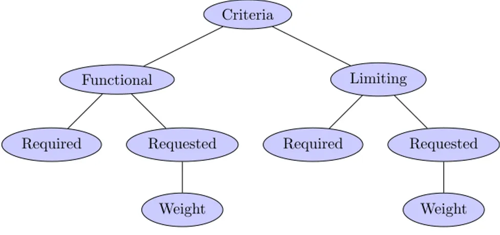
The work of forming the goal specification is based on the interpreted cus-tomer needs. To systematically generate properties that fulfills the needs, cat-egorization is made. The purpose of the catcat-egorization process is to concretize and visualize the properties to be able to determine their value for the end product. The input to the categorization process is called criterion, see figure 6. Dividing criteria into Functional and Limiting categories is the first step [20] and further dividing into subcategories Required and Request is the next. A functional criterion can mostly be written as a ”verb + noun”, for example ”carry load” [20]. Limiting criteria are such as ”maximum weight of x kg” or ”top speed of at least y km/h”.
When all criteria have been divided into these two categories both the func-tional and limiting criteria are divided into subcategories: Required and Re-quested. Criteria that goes into the Required category are ones that are re-quired to be found a property for to achieve the properties necessary to reach the minimum acceptance level from customers. When speaking about the im-portance of a required criteria, the word shall is used [23]. Requested criteria that are wished for and are considered to be able to add substantial value to the product but are not necessary to reach the minimum acceptance level. These are treated with the word Should. Request criteria are given a number describ-ing their weight of importance or their potential contribution to the product if implemented.
In the last step of the process of creating the goal specification all the criteria are viewed upon in different aspects [20]. This is to ensure that all aspects of
Criteria Functional Required Requested Weight Limiting Required Requested Weight
Figure 6: Process for sorting criteria into what type of property is to be found.
the product are reviewed for each and every criterion. Aspects are for example performance, environment, safety, weight and geometry, and relevant aspects are selected for the project.
6.3
Concept Generation
Concept generation is basically problem solving and the outcome depends there-fore on the person(s) involved in it (experience, incentives etc). There are mainly two types of tools described in the literature to improve the outcome from this process: creative tools and systematic tools. Creative tools are such as brain-storming [24], the 6-3-5-method [25], and the Gordon technique [20], which all of them are preferably performed in groups of people. Characteristic for the creative tools are that they are solution oriented and strives for generating solu-tions for the problem that the product is to solve. Systematic tools are however function oriented and strives for generating solutions for each function that the product is to have. Common for both tools are that they strive to avoid com-mon pitfalls. Such pitfalls are: proceeding with a predetermined concept before other concepts have been evaluated, inefficiency in concept generation and fail-ure to look beyond what is already known in the team or the ideas that comes up early. [20]
Functions are to give a product its properties and it is the solution to how
they are achieved. Based on the product specification, functions are to be
main function is defined and it includes the most essential functions that the product has. The main function can often be used as the product name and is the main reason for a customer to buy the product. To define the main function, the customer needs and product properties are consulted to find what might be most valuable to the end user. The main function is the springboard for the concept generation process.
A four step process is used to generate the concepts from which one or a few are to be selected for further development in the concepts selection process later on. The aim is to generate a wide variety of concepts and the more concepts that are generated the better. The first step is to clarify the problem that the product is intended to solve. This is done by decomposing the problem into subproblems and then identifying and focusing on solving critical subproblems. The second step is to search externally for information. This includes consulting experts, interviewing users, searching patents, literature and similar products. The third step is to search internally by generating ideas within the team. Fourthly the data collected from previous steps is explored systematically. By using a systematic approach, tools for generating solutions for subproblems are used. Unlike the process as described by Ulrich and Eppinger which is a five step process with reflection as the last step, reflection is done constantly as a part of every of the four steps in this work. This is to improve chances of finding and correcting errors as early as possible.
Decomposition of problems is a tool to solve complex problems [21]. The first step is to decompose the problem functionally as a black box. The black box comprises the main function and it has inputs and outputs consisting of material, energy and signals. The inputs are processed by the black box to give the intended output. E.g. with gasoline as input (energy, material) to a car (black box), the output can be exhausts (material) and kinetics (energy). The most crucial inputs and outputs of the product are identified and defined as critical subproblems to be solved. It is believed that by solving the critical subproblems, many of the remaining problems will be easier to solve. To discover what a black box can consist of to produce a certain output, a function diagram is made. To the left in the diagram are the inputs energy, material and signal. To the right is the output which in this diagram is a critical subproblem. In between the inputs and the output are functions and arrows describing the relationships and input flow through them. The inputs and the output are facts, the functions are variables.
further development, a morphological matrix [21] is set up. It states functions as variables that are based upon the product specification and the problem to be solved. The possible solutions for each variable is generated by searching
externally and internally. Patents and supplier websites are sources among
others that are used to find solution ideas. Combined with internal search, which can be for example brainstorming, the morphological matrix is fed with up to four solutions for each function. With a morphological matrix as a base, concepts are generated systematically by combining functions that are deemed to be realistic.
6.4
Concept Selection
With a wide variety of concepts generated in the concept generation process, the aim with the concept selection process is to narrow down the number of concepts to one or two. The process is done in two steps. The first step is to narrow down the number of concepts by screening and the second to narrow down even further by concept scoring [21]. A reference concept, the current design, is included in this screening and the parameters that are used for screening are selected from the product specification. Suitable parameters are such that can be determined by imagining what a physical prototype might look like and what properties it might have based on the concept composition.
The screening is done using a three grade scale where - is negative, 0 is neutral and + is positive. By summing up each grade and subtracting the number of negatives from the number of positives, a net score is calculated (neutrals doesn’t affect the net score). The higher the net score, the higher the rank (rank 1 is the highest). Concepts that are ranked 1, 2 and 3 are selected for continued development and the rest are canceled. If two concepts shares the same rank, both are selected for continued development. The first narrowing is now done.
With fewer concepts left for evaluation, the remaining concepts are taken through the procedure of concept scoring. Using the same parameters as in the concept screening, each parameter is assigned a weight as a percentage. Based on the property type each parameter has been assigned with in the product specification, a weight is calculated as a percentage of the summed up weights based on the weight of the property (weight of shall is 5). With for example three properties: Shall, Should, 4 and Should, 2, the summed up weight is 5 + 4 + 2 = 11 and the weight percentage used in the concept scoring procedure
is 114 = 36% for the property with type Should, 4.
This procedure scores the concepts by how well they are assumed to perform or achieve a certain property and a rating of 0-5 is assigned to each parame-ter. The rating multiplied by the weight percentage of the parameter gives the weighted score for the concept. Total scores for the concepts are calculated by summing up the weighted scores for each of them. The total scores are then compared and used for ranking. The higher the total score, the better and the one concept with the highest total score is selected for continued development. If two or more concepts receives the highest total score, the one most deemed most feasible is selected.
6.5
Concept Development and Modeling
The selected concept is described in detail and a model of the concept is rendered using the 3D CAD software SolidWorks [26].
7
Real Gas Modeling
Low density gases such as air can be modeled using the ideal gas law pV = nRT in which p is pressure, V volume, n the number of moles of substance, R the Avogadro constant and T the temperature [27].
Real gases can be modeled by adding a compressibility factor z to the ideal gas law: pV = znRT . The compressibility factor depends on material, pressure and temperature, and is approximately z = 1 for air at absolute pressures below 100 bar ( 75.000 mmHg) and at room temperature (300 K) [28].
In a closed system with a known gas, a known amount of the gas, and constant temperature, the right side of the real gas law equation is constant pV = C. With this equation the pressure can be calculated for any volume and vice versa and it is relevant for a system with different states. For example, in a closed system that can be in two states with different volumes and pressures,
the volumes and pressures of respective state can be set as p1V1 = p2V2 if at
three of the variables are known. If for example p1, V1 and V2 are known, p2
can be calculated as
p2=
p1V1
V2
8
Development of Afterload Concept
The scope of this work is delimited by not taking explicit consideration of ster-ilizability or manufacturability. Neither are prototypes to be built. Since the focus of this work is placed on physics and mechanics for controlling the af-terload, improvements of aspects such as anatomical or biological are beyond the scope. The scope is set by the development team in conjunction with the
supervisor at Igel¨osa and since the aim of this heart evaluation system in short
term is to be used in research by the supervisor, he is also considered to be an end user. The global backlog is found in appendix B.
8.1
Problem Definition and Identification of Needs
Aiming to produce results in an efficient way, identification of customer needs are done through interviews with persons considered to possess enough knowledge on the subject to make concept design decisions. Studying literature on the subject might provide more general understanding of the problem that is to be solved, however the interviews are expected to provide sufficient information and literature as a main source is thus put aside.
Stakeholders are interviewed and asked about what’s bad about current so-lution, what’s good about it and what it needs. Other information gathered during interview is also collected. By running the interviews with only three guide questions and an open miscellaneous question, the answers are expected to fulfill first four aims of the process as described in the method section. The fifth aim regarding collective understanding of the problem within the development team is met due to there is only one person in the team.
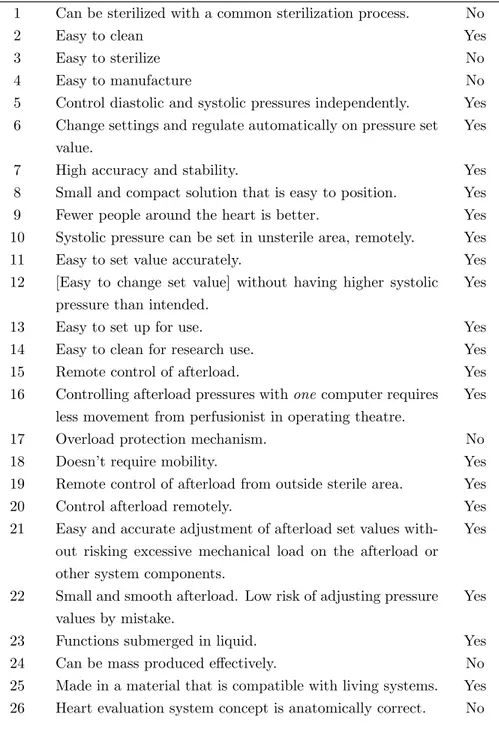
Four interviews, see appendix A, are performed with persons with differ-ent areas of expertise: electronics engineering, mechanical engineering, clini-cal/surgeon. All four subjects are experienced with the heart evaluation system and more or less familiar with the limitations of the current solution. To gather key facts, the interviews switched between focusing on the afterload, the whole evaluation system and the theory and history of heart evaluation. The opinions gathered from the interviews are interpreted to be focused on the technical as-pects of the afterload and condensed in table 1. To filter the interview outcome further, the interpretations are compared to the scope of the work to ensure validity.
Table 1: Compilation of interpretations from interviews and scope check.
I/W# Interview interpretation Scope
1 Can be sterilized with a common sterilization process. No
2 Easy to clean Yes
3 Easy to sterilize No
4 Easy to manufacture No
5 Control diastolic and systolic pressures independently. Yes
6 Change settings and regulate automatically on pressure set
value.
Yes
7 High accuracy and stability. Yes
8 Small and compact solution that is easy to position. Yes
9 Fewer people around the heart is better. Yes
10 Systolic pressure can be set in unsterile area, remotely. Yes
11 Easy to set value accurately. Yes
12 [Easy to change set value] without having higher systolic
pressure than intended.
Yes
13 Easy to set up for use. Yes
14 Easy to clean for research use. Yes
15 Remote control of afterload. Yes
16 Controlling afterload pressures with one computer requires
less movement from perfusionist in operating theatre.
Yes
17 Overload protection mechanism. No
18 Doesn’t require mobility. Yes
19 Remote control of afterload from outside sterile area. Yes
20 Control afterload remotely. Yes
21 Easy and accurate adjustment of afterload set values
with-out risking excessive mechanical load on the afterload or other system components.
Yes
22 Small and smooth afterload. Low risk of adjusting pressure
values by mistake.
Yes
23 Functions submerged in liquid. Yes
24 Can be mass produced effectively. No
25 Made in a material that is compatible with living systems. Yes
27 Heart evaluation system allows extensive data to be col-lected.
No
28 Systolic and diastolic pressures can be tested independently. Yes
29 A robust design that prevents significant leakages or other
weaknesses that affects the evaluation performance.
Yes
30 Pressure limits within a ten-range. Yes
31 High accuracy and stability on pressure value. Yes
Information gathered from the four interviews is considered to be sufficient to define the problem and further interview iterations is considered unnecessary. The problem is defined as: The control of the systolic pressure made by the afterload cannot be done remotely and the afterload cannot produce enough pulse pressure to evaluate the whole range of relevant pressure settings.
8.1.1 Analysis of Needs
With table 1 as springboard, the needs are interpreted and further condensed after reflection.
The need for a design suitable for sterilization, preferably with a common sterilization process, is something that comes up in more than one of the inter-views. Sterilization suitability is beyond the scope of this work and is therefore not made a need. It will however be taken implicitly into consideration in the designing process to avoid something that is obviously not sterilizable.
In research use, it is sometimes only necessary to have clean components i.e. sterility is not necessary. This often takes shape in re-usage of single-use components and to allow this behavior is encouraged by the principal of this work. That is why the possibility to easily be able to clean the afterload is needed. The cleaning can be done by hand with a dish brush or possibly with a dish washer intended for such use.
It is stated in the limitations of this work that it will not include manufac-turability and ”easy to manufacture” which are therefore not included as needs. However, with the same background as above mentioned on the sterilization, manufacturability will be taken into consideration implicitly. A design that by obvious reasons cannot be manufactured is of little use.
Even though the systolic and diastolic pressures are interrelated in the hu-man body, they aren’t necessarily in the heart evaluation system. With the
afterload the diastolic and systolic pressures should be possible to evaluate in-dependently.
Automatic control by computerized regulation of the pressure set value. Once the set value of a pressure has been changed, the balloon pressure will automatically change to create the desired afterload pressure. To make the automatic regulations useful, it must have what has been interpreted as high accuracy and stability: if a systolic pressure of 130 mmHg is to be tested for, the afterload should regulate between at least 130 mmHg and reach maximum 139 mmHg. Both diastolic and systolic pressure settings should be controlled from the same computer and it should be easy to change pressures without risk of getting too high a pressure.
From a surgeon’s point of view, the work space which is sterile, must be easy to keep sterile and also have space for surgical work. It is not unusual to have six hands collaborating at the same time on the same organ, which means that work space is crucial. A small and smooth afterload will make more space for surgeons to work in and better access to the heart. The smoothness is to prevent sharp edges and excessive protrusions that might hook onto and break the sterile gloves that are worn in the sterile space. It is also to prevent the afterload from being unintentionally moved or from settings unintentionally being changed.
Better access to the heart in the evaluation system will be further improved by decreasing the number of people in the sterile space. By allowing control of the afterload from a distance, the perfusionist can be taken out of the sterile space. This will not only improve the maintenance of sterility around the heart (perfusionists are not sterile dressed), but also make more room for surgeons to work. Based on the heart evaluations done in research that have been run with the current equipment and by imagining how a commercial product might look, the radius of the sterile field centered on the heart, when doing heart evaluation,
is approximately 30 cm1.
Setting up the afterload which includes connecting it to the evaluation circuit and the balloon pressure system should be easy. It should also preferably be easy to disconnect and disassemble the afterload for cleaning when used in research where sterility is not necessary.
Since the heart evaluation system is not intended to be mobile, design param-eters crucial for mobility, for example weight, must not be considered. Though
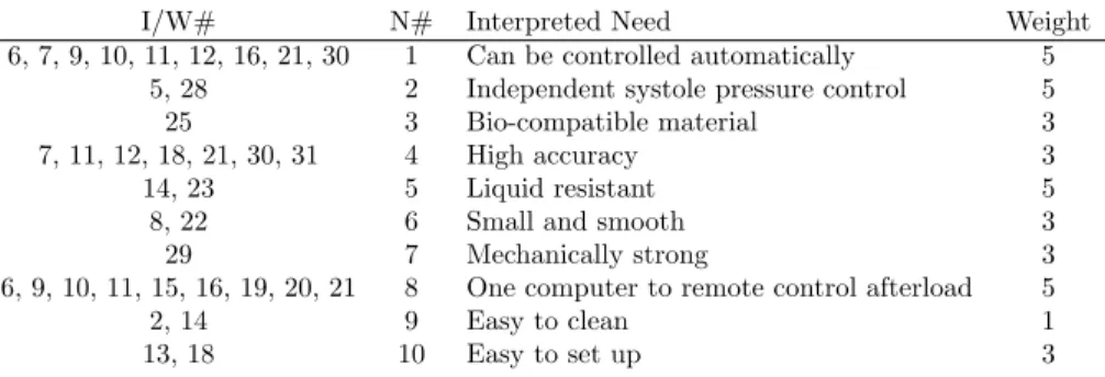
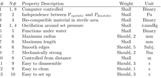
Table 2: Identified and interpreted customer needs. Weight scale 1-5.
I/W# N# Interpreted Need Weight
6, 7, 9, 10, 11, 12, 16, 21, 30 1 Can be controlled automatically 5
5, 28 2 Independent systole pressure control 5
25 3 Bio-compatible material 3
7, 11, 12, 18, 21, 30, 31 4 High accuracy 3
14, 23 5 Liquid resistant 5
8, 22 6 Small and smooth 3
29 7 Mechanically strong 3
6, 9, 10, 11, 15, 16, 19, 20, 21 8 One computer to remote control afterload 5
2, 14 9 Easy to clean 1
13, 18 10 Easy to set up 3
high weight has no purpose in itself, not taking it into consideration might add to a more robust and safe design.
The need for having a liquid resistant afterload is expressed through the need for being able to submerge the afterload into the liquid solution that is used to perfuse the heart. Currently neither the heart nor the afterload is submerged into liquid during heart evaluation, but due to the wet environment in which the afterload operates, liquid resistance of the afterload is needed. During the interviews there have been expressed an interest in evaluating the heart while it is submerged into liquid solution.
Information from the interviews that were not deemed as explicit needs but still worth taking into consideration was collected. The transition time between set values of afterload pressures are better to be long than short. It is said that waiting a minute for a adaption to a changed set value in afterload pressure is no problem, or even might be preferred, as long as the transition is controlled and managed carefully. The characteristics of the mathematical function describing
the balloon pressure should be discontinuous, dPdt=0, at set pressure value.
It should be noticed that interview information and items in table 1 that are outside the scope of this work will be taken into consideration where applicable since they will most probably be a part of future work.
The results from the reflections on the interviews and the interpreted needs are shown in table 2. The assignment of weights to the interpreted needs are done in consultation with the interviewees.
Table 3: Measurable properties that fulfills the needs. Weight scale 1-5.
P# N# Property Description Weight Unit
1 1, 8 Computer controlled Shall Binary
2 2 Independence between Psystolicand Pdiastolic Shall Pa
3 3 Bio-compatible material in sterile area Shall Binary
4 1, 4 Oscillation around set pressure Shall ±mmHg
5 5 Functions under water Shall Binary
6 6 Maximum radius Should, 2 mm
7 6 Maximum length Shall mm
8 6 Smooth edges Should, 5 Subj.
9 7 Mechanically strong Should, 2 Nm
10 8 Controlled from distance Shall m
11 9 Easy to disassemble Should, 3 s
12 9 Easy to clean Should, 1 s
13 10 Easy to set up Should, 3 s
8.2
Product Specification
To create a product specification that is as accurate as possible and hold a reasonable high quality with regards to the level of novelty in this subject, the product specification method based on the six aims is considered suitable in this work. It is a systematic approach to create a product specification that can be verified and validated by people not having thorough understanding of the problem thanks to clear metrics. Clear metrics is a strength in a work con-cerning a technical problem and being able the measure the product properties is advantageous in case different solutions are to be compared. A systematic approach also increases the reproducibility of the work since and is better suited for single-person development teams.
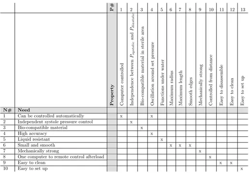
The properties that are chosen to make the afterload do what is needed are found in table 3. To verify that all needs are fulfilled with at least one property, a need-property-matrix is generated to visualize it, see table 4. There is one property that fulfills two needs: property of oscillation around set pressures. Since this afterload is a pioneering product there aren’t competing products that can be used as a benchmark.
Table 5 is the goal specifications of the improved afterload. All properties have been assigned physical, binary or subjective units that can be used to measure how well each of the properties are fulfilled by a certain design concept.
Table 4: A visual way of verifying that all needs are satisfied by at least one property. P# 1 2 3 4 5 6 7 8 9 10 11 12 13 Prop ert y Computer con trolled Indep endence b et w een Psy stol ic and Pdiastol ic Bio-compatible material in sterile area Oscillation around se t pressure F unctions under w ater Maxim um rad ius Maxim um length Smo oth edges Mec hanically stron g Con trolled from distance Easy to disassem ble Easy to clean Easy to set up N# Need
1 Can be controlled automatically x x 2 Independent systole pressure control x 3 Bio-compatible material x
4 High accuracy x
5 Liquid resistant x
6 Small and smooth x x x
7 Mechanically strong x
8 One computer to remote control afterload x
9 Easy to clean x x
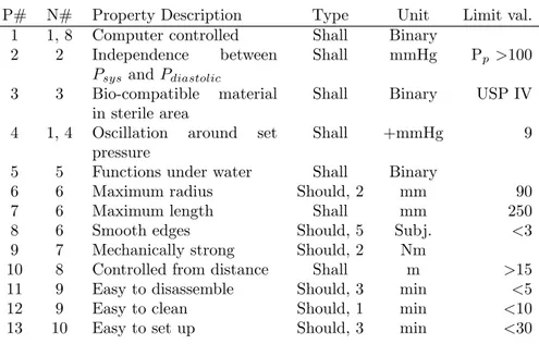
Table 5: Goal specification.
P# N# Property Description Type Unit Limit val.
1 1, 8 Computer controlled Shall Binary
2 2 Independence between
Psys and Pdiastolic
Shall mmHg Pp >100
3 3 Bio-compatible material
in sterile area
Shall Binary USP IV
4 1, 4 Oscillation around set
pressure
Shall +mmHg 9
5 5 Functions under water Shall Binary
6 6 Maximum radius Should, 2 mm 90
7 6 Maximum length Shall mm 250
8 6 Smooth edges Should, 5 Subj. <3
9 7 Mechanically strong Should, 2 Nm
10 8 Controlled from distance Shall m >15
11 9 Easy to disassemble Should, 3 min <5
12 9 Easy to clean Should, 1 min <10
13 10 Easy to set up Should, 3 min <30
The limit value declares the limit that a certain design concept much be able to reach to be sufficient. The final product specification is found in appendix C
8.3
Concept Generation and Selection
In this work a systematic approach is chosen because it is deemed to fit well with the team size and it is believed to be more repeatable and reproducible than the creative approach. It is also considered to be more time efficient when the level of experience of the development team is limited due to e.g. high level of novelty of the work.
The main function is ”computer controlled afterload”. The afterload is rep-resented as a black box, see figure 7. Further problem decomposition leads to a function diagram, see figure 8.
Computer controlled afterload Signal (elec.) Material (air) Energy (Pdiastolic) Signal (pressure) Material (air) Energy (Psys)
Figure 7: The afterload represented as a black box with inputs and outputs.
Energy Keep air
pressure
Control air pressure
Material Receive air away airGive
Create pulse pressure Signal Receive signal Return signal Heart’s systolic pressure evaluated
Figure 8: Function diagram focusing on the critical subproblem of evaluating the systolic pressure of a heart.
Table 6: A morphological matrix for visualizing alternative solutions to sub-problems.
1 2 3 4
Valve type Proportional Roller Pinch Servo control
Computer control Valve with built-in actuator External ac-tuator Signal/energy transmission (com-puter to actuator)
Cable Bluetooth Wifi
Product architec-ture Integrated in afterload Module near afterload, dist.<10 cm Module out-side sterile space Bio-compatibility of valve Bio-compatible, re-usable Bio-compatible, single-use Not bio-compatible, re-usable Not bio-compatible, single-use Psystoliccontrol Variable
vol-ume
Variable flow resistance
Number of valves 1 2-5 6-10 0
8.3.1 Identification of Critical Subproblems
A critical subproblem that is initially focused on is the problem of controlling
the systolic pressure in the balloon independently of the pulse pressure. A
morphological matrix is set up, see table 6, to visualize ideas for alternative solutions. Questions that arise regarding why the pulse pressure cannot be 100 mmHg with current solution:
• Is ∆P over the balloon valve too low which causes the air flow to be too
low with higher Psystolic?
• Is the balloon volume too small (when valve is closed)?
8.3.2 Generation of Concepts
Based on the morphological matrix, concepts are generated from combinations of solutions for the different sub-problems. Six concepts (named A-F) are selected and presented in table 7. Concept sketches are presented in appendix D.
Table 7: Concepts generated from combinations in the morphological matrix.
Concepts
A B C D E F
Valve type Roller Pinch Pinch Solenoid Proportional Proportional Computer control Valve with
built-in actuator Valve with built-in actuator Valve with built-in actuator Valve with built-in actuator Valve with built-in actuator Valve with built-in actuator Signal/energy transmission (com-puter to actuator)
Cable Cable Cable Cable Cable Cable
Product architec-ture Module out-side sterile space Module out-side sterile space Module out-side sterile space Module out-side sterile space Module out-side sterile space Module out-side sterile space Bio-compatibility of valve Not bio-compatible, single-use Not bio-compatible, single-use Not bio-compatible, single-use Not bio-compatible, single-use Not bio-compatible, single-use Not bio-compatible, single-use Psystoliccontrol Variable
vol-ume Variable vol-ume Variable flow resistance Variable flow resistance Variable flow resistance Variable flow resistance Number of valves 1 2-5 2-5 1 2-5 1 8.3.3 Concept A
Concept A consists of a variable balloon volume to control the systolic pressure. The valve used in this concept is not a valve per definition, just an computer controlled actuator for controlling the rotation of a tube roller. This concept can built with everything but the afterload and a piece of tube connected to the afterload outside the sterile field. An advantage with this is that many of the components aren’t required to be sterilized and/or bio-compatible.
8.3.4 Concept B
Concept B consists of multiple pinch clamps mounted sequentially on a soft tube and by completely occluding the tube in different places variates the balloon volume. This concept can be built outside the sterile field and connects to the afterload through a single tube.
8.3.5 Concept C
Concept C consists of multiple pinch clamps mounted sequentially on a soft tube and by partially occluding the tube in different places variates the gas flow through the tube during diastole (balloon collapsed). This concept can be built outside the sterile field and connects to the afterload through a single tube.
8.3.6 Concept D
Concept D consists of a solenoid valve mounted on a tube which is connected to the afterload. The solenoid valve works as a pressure relief valve and is opened when the balloon pressure reaches a set value. To comprise the whole range of pressures to evaluate, the balloon volume is designed to reach high pressures during systole, i.e. a relatively small balloon volume.
8.3.7 Concept E
Concept E consists of a tube connected to the balloon volume to which a pro-portional valve is mounted to the tube end. The valve is then connected to a compliance and the compliance is in turn connected to another proportional valve. This way the differential pressure over valve connected to the afterload can be controlled by controlling the second valve.
8.3.8 Concept F
Concept F is analog with the patented solution with the difference in that the systolic pressure control valve is moved outside the sterile field and is replaced by a proportional computer controlled valve. This way the systolic pressure is controlled by controlling the gas flow through the valve.
8.4
Concept Selection
The selection of concept is based on the systematic approach taken to concept development hitherto. By using weighting and scoring as a basis for decision making on what concept is to be selected, the decision making is made objective and efficient. This is suitable with regards to the level of novelty of the work and also the level of experience within the development team.
Screening, see table 8, and scoring, see table 9, of concepts leads to selection for further development of concept A.
9
Development of Selected Concept
The process for development of selected concepts is suitable since it improves the depth of the understanding of the selected concept. For modeling the physics of the selected concept, the real gas law is deemed suitable since it composes the
Table 8: Concept screening Concepts
Selection criteria A B C D E F Ref.
Ease of control + - - + - 0 -Accuracy + - - 0 + 0 -Ease of (dis)assembly + 0 - + 0 0 -Ease of cleaning 0 - - 0 0 0 -Ease of use + 0 0 + 0 + + Spread in space 0 - - + - - + Robustness + - - + 0 + 0 Sum +’s 5 0 0 5 1 2 2 Sum 0’s 2 2 1 2 4 4 1 Sum -’s 0 5 6 0 2 1 4 Net score 5 -5 -6 5 -1 1 -2 Rank 1 5 6 1 3 2 4
Continue? Yes No No Yes Yes Yes No
Table 9: Concept scoring. Rating 0-5
Concepts
A D E F
Selection Criteria
Weight Rating Weighted Score Rating Weighted Score Rating Weighted Score Rating Weighted Score Ease of con-trol 24% 4 0.96 2 0.48 1 0.24 3 0.72 Accuracy 24% 5 1.2 3 0.72 4 0.96 4 0.96 Ease of (dis)assembly 14% 5 0.7 5 0.7 5 0.7 5 0.7 Ease of cleaning 5% 2 0.1 3 0.15 3 0.15 3 0.15 Ease of use 14% 3 0.42 3 0.42 2 0.28 3 0.42 Spread in space 9% 3 0.27 5 0.45 1 0.09 2 0.18 Robustness 10% 4 0.4 5 0.5 3 0.3 3 0.3 Total Score 4.05 3.42 2.72 3.42 Rank 1 2 3 2 Continue? Develop No No No
necessary variables and is suitable in the environment that the concept is to be used in.
A sketch of Concept A is shown in figure 9. It consists of five components excluding the afterload and the diastolic pressure pump and compliance (items 36, 42, 44 and 46 in figure 3) and are as follows: a four-way connector, a check valve, a pressure measurement device, a soft tube and a tube roller. It is a pneu-matic system and is based on the real gas law to control the pressure by variating the volume when the pressure-volume ratio is constant (P V =znRT =constant).
The balloon volume, Vballoon, is defined as the volume inside the afterload
balloon and the four-way connector and is delimited by the tube roller occlu-sion, the pressure measurement device and the check valve. During diastole Pballoon=Pdiastolic and during systole Pballoon=Psystolic. With the assumption
Figure 9: Principle sketch for concept A. A tube roller is used to variate the
volume to control Psystolic based on the real gas law.
that the afterload balloon is compressed a certain volume for a certain car-diac output, the dimensioning of the system can be made in regard to
differ-ent parameters. Pballoon is divided into two separate volumes: Paf terload and
Psystem. The former is the balloon volume inside the afterload only and the
latter Psystem= Pballoon− Paf terload, i.e. ∆Paf terload=constant. Dimensioning
with regard to Vsystemis calculated with
Vsystem=
PsystolicVsystolic− PdiastolicVdiastolic
Pdiastolic− Psystolic
and with regard to Psystolicwith
Psystolic=
PdiastolicVsystem+ VdiastolicPdiastolic
Vsystem+ Vsystolic
(9.2)
which are both derived from equation 7.1.
9.1
3D CAD Modeling
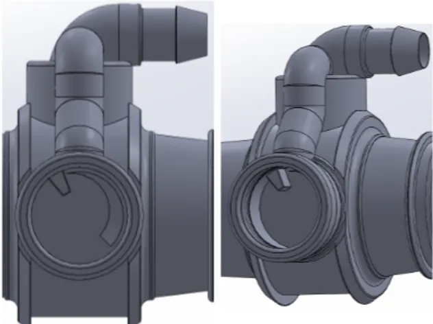
To decrease the level of abstraction in the concept that is selected, using visual representations is considered to be advantageous, not only when discussing the work, but also to improve the chance of finding weaknesses in the concept.
A 3D CAD model of concept A is made based on the current design of the afterload, see figure 10. The one-way valve and knob is removed and left is a hose barb to connect a tube between the afterload and the four-way connector. To visualize the concept of having only the afterload inside the sterile field a 3D CAD model is made of the whole system for afterload control, see figure 11
Figure 10: A model of concept A.
10
Discussion
A latent problem with this design that might occur is when the tube roller
rotates to decrease Vballoonduring diastole. Pballoonwill then increase according
to the real gas law to a pressure greater than Pdiastolic. This pressure must be
relieved to allow independence between all pressure variables. Solutions, based on Poisseuille’s law, are identified and visualized in figure 12.
One solution is to connect the open soft tube end of to the Pdiastolic
Figure 11: Concept sketch of concept A afterload inside the sterile field and all other components outside of it.
Pdiastolic ≤ Pballoon the pressure difference over the tube roller will create gas
flow from Vballoonto the Pdiastolic compliance.
A second solution is to have the soft tube end open to atmosphere and allow relief by adjusting the tube roller occlusion setting to allow some leakage. This creates pressure relief by the flow that occurs due to the same pressure difference over the tube roller. With this solution, the flow is equal or greater than in the
previous solution because Pballoon− Patmosphere≥ Pballoon− Pdiastolic.
A third solution is to connect a valve to Vballoonand which can be opened to
relief Pballoonto equal or below Pdiastolic when Vballoonis decreasing. The valve
is then closed and Pdiastolic is established in the new Vballoon. In this solution
the soft tube is completely occluded by the tube roller to minimize leakage. Concept A2.1, see figure 13, is thought to be the most feasible solution be-cause it is assumed to be easier to set up the system if the tube roller occlusion doesn’t have to be set to allow a certain leakage instead of completely occluding the tube. Full occlusion of the tube is assumed to result in an insignificant leak-age since everything always leaks more or less in a pressurized system. Further investigation of this latent problem is recommended for future work.
Another thing to investigate in future work is the impact of compliance in Vballoon on the pulse characteristics. Some compliance exists in the aorta and
amount depends on the length of it. Also is there compliance in the pneumatic system tubing, but this compliance might be negligible. Another solution for
Concept A. Overpressure problem. A1. Tube roller leakage. A1.1. Connect tube end to Pdiastolic compliance. A1.2. Keep tube end open to atmospheric
pressure.
A2. Valve for Pballoonrelief.
A2.1. Valve connected to Vballoon.
Figure 12: Development of concept A regarding the latent problem of Pballoon
Figure 13: Principle sketch for concept A2.1. A valve is added to Vballoon to
allow pressure release, otherwise Pballoon> Pdiastolic when Vballoonis decreased
because of the check valve.
variation of Vballoon is by replacing the tube roller with a syringe and mount
the syringe in a two-way syringe pump. This way the whole system easily can be set up by existing technology.
Sources of error are identified as possible incorrect interpretation of inter-view answers, not enough external search in the concept generation process, subjectivity in the concept selection process among other. Regarding reliability and validity of the input to this work, the sources are deemed to be reliable due to them being not only stakeholders but experts in the heart evaluation work. Their expertise grants for a relatively high degree of validity. A longer and more thorough interview template could have increased the validity of the information, but meanwhile more information is not always better.
The four persons interviewed in this work are all closely connected to Igel¨osa
through employment, postgraduate research and company owner. This group of people is believed to hold a high level of knowledge regarding the heart evalua-tion system described in this work. However, more general knowledge regarding the subject could have changed the outcome of the work to a more general so-lution to be used in other fields of engineering. More general knowledge could have been obtained through for example literature. The scope of the work was
set in conjunction with the supervisor at Igel¨osa and the engineer with most
11
Conclusion
In this work, a concept for controlling an afterload for an ex vivo heart evaluation system has been developed and described. It results in a concept which is based on the real gas law to control the flow resistance through an afterload. Equations for calculating the ratios between volumes during diastole versus systole have been presented. These equations are believed to be of importance in the future work of designing a physical prototype. An improvement that has been made, which wasn’t stated as a requirement, is that the design of the afterload is simpler and is fully integrated in the afterload. This should not only make the production costs lower but also the design more robust. The concept presented in this work is believed to be superior to the current afterload design by having solutions for the three main problems described as the aim of the work. By adding to the knowledge around the heart evaluation system and this work has possibly taken the heart evaluation system one step closer to be used to save lives and by that the purpose is fulfilled.
![Figure 1: Internal anatomy of the heart [5] licensed under CC 3.0.](https://thumb-eu.123doks.com/thumbv2/5dokorg/3968396.77657/8.918.197.720.601.904/figure-internal-anatomy-heart-licensed-cc.webp)
![Figure 2: Illustration from patent for heart evaluation device [18] illustrating a heart with afterloads connected to the aorta and the pulmonary artery re-spectively](https://thumb-eu.123doks.com/thumbv2/5dokorg/3968396.77657/12.918.212.716.253.460/figure-illustration-evaluation-illustrating-afterloads-connected-pulmonary-spectively.webp)
![Figure 4: Illustration of the afterload in cross section view [18]. The afterloads labeled Fig](https://thumb-eu.123doks.com/thumbv2/5dokorg/3968396.77657/13.918.280.636.179.667/figure-illustration-afterload-cross-section-view-afterloads-labeled.webp)