IT 13 065
Examensarbete 30 hp
September 2013
Object Oriented Design Pattern
Extraction From Java Source Code
Rupesh Acharya
Institutionen för informationsteknologi
Department of Information Technology
Teknisk- naturvetenskaplig fakultet UTH-enheten Besöksadress: Ångströmlaboratoriet Lägerhyddsvägen 1 Hus 4, Plan 0 Postadress: Box 536 751 21 Uppsala Telefon: 018 – 471 30 03 Telefax: 018 – 471 30 00 Hemsida: http://www.teknat.uu.se/student
Abstract
Object Oriented Design Pattern Extraction From Java
Source Code
Rupesh Acharya
In case of software architecture reconstruction, design pattern detection plays a vital role since its presence reflects the point of design decision. Currently most of the studied approaches only focus on the Gang of Four (GOF) design patterns so those tools are not flexible enough to identify other proprietary pattern instances. Moreover, the GOF design pattern can be implemented in various ways which many of the tools suffers to detect. Apart from that not only design pattern is of vital importance for software architecture reconstruction but other patterns like anti-patterns and presence of bad smell code are also equally important. So the approach discussed here is a solution for detecting any pattern instances (not only GOF patterns) from the source code provided that relevant information is extracted during the static analysis phase.
Our approach is based on the graph pattern matching technique where the source code is modeled as a graph and the pattern to search for is provided as a graph query pattern. For the detection of patterns we focus on structural and behavioral analysis of source code as in the case of a tool called PINOT. The novelty of our approach compared to PINOT is that the choice of behavioral analyzers can be provided as a constraint in the graph query pattern unlike hardcoded in PINOT. Moreover, we can provide more than one constraint in the graph query pattern at node, edge or complete graph level hence, we can compose our query pattern as we want which helps us to specify different kind of new patterns and handle varying implementations of design patterns as well.
Tryckt av: Reprocentralen ITC IT 13 065
Examinator: Ivan Christoff Ämnesgranskare: Ivan Christoff Handledare: Yan Liu
Acknowledgement
First of all, I am really glad to be admitted in this wonderful Sino-Swedish double degree masters program. I would like to thank both the Tongji University and Uppsala University administration for establishing such an amazing cooperation program. I would personally like to thank Mr. Anders Berglund and Ivan Christoff for all the support and consultation they provided during the whole study period.
I would like to express my deepest gratitude to my Supervisor, Professor Liu Yan for her continuous supervision, guidance and support. Her friendly nature and great advices really helped me complete this thesis successfully. The program coordinator Fion Wang and Mei Li from Tongji University are the ones whom I can never forget for providing me all the guidance and help acting as both, a friend and a guardian. They were the ones who were always there for me whenever I had any problem.
Utmost among all, I would like to thank Kevin (Zhang Xian Peng), from the bottom of my heart, for being such a great friend and helping me in every step in the best possible way he could. He is one of my best friends whom I can never forget in my life. I am greatly obliged to my country mates as well, to name few of them, Rajiv Ojha, Praveen Yadav, Pratik Poudel, Subash Bhattarai, Bhavana Rajbanshi, Madhu Shakya and Alka Sapkota for all the moral support they gave me and never letting me feel away from home. Moreover, I can never forget Tommy Mattsson, Ziad Benslimane, Patcharee Pianwittyasakun, Ashish Lamichhane, Amendra Shrestha, Ekta Shrestha and Aahana Shrestha for all their great encouragement and faith on me which motivated me to accomplish things all the way through.
Nonetheless, I would like to thank all my friends and colleagues both in Sweden and China who have helped me, through any means, directly or indirectly in completing my study and thesis. Please don’t be sad because I didn’t mention your name here, I will never forget your support and I am really thankful to you all.
Table of Contents
Chapter 1 Introduction ... 1 1.1 Introduction ... 1 1.2 Background ... 1 1.2.1 Software Engineering ... 1 1.2.2 Software Architecture ... 1 1.2.3 Software Maintenance ... 2 1.2.4 Reverse Engineering ... 21.2.5 Software Architecture Reconstruction (SAR) ... 3
1.2.6 Design Patterns ... 3
1.2.7 Design Pattern Detection ... 5
1.3 Statement of the Problem ... 6
1.4 Thesis Outline ... 6
Chapter 2 Literature Review ... 7
2.1 Introduction ... 7
2.2 Design pattern detection approaches ... 7
2.2.1 DPD using similarity scoring ... 7
2.2.2 DPD by template matching ... 8 2.2.3 Model driven DPD... 9 2.2.4 DNIT ... 9 2.2.5 Ptidej ... 10 2.2.6 SPQR ... 10 2.2.7 Marple ... 11 2.2.8 Fujaba ... 13 2.2.9 Pinot ... 13 2.3 Our Approach ... 15
Chapter 3 Design Pattern Detection Approach ... 16
3.1 Introduction ... 16
3.2 Design Pattern Extraction... 16
3.2.1 Static Analysis ... 17
3.2.2 Pattern Matching... 17
Chapter 4 BIGPD Design and Implementation ... 25
4.1 BIGPD Design... 25
4.2 Information Extractor ... 26
4.3 Graph Modeler ... 27
4.4 Graph Pattern Searcher... 28
4.5 Front End ... 29
4.6 Composing Complex Constraints ... 32
Chapter 5 Experimentation and Result Analysis ... 34
5.1 Design Pattern Detection ... 34
5.1.1 Result Analysis ... 35
5.2 Identifying variant of design pattern ... 35
5.3 Inference ... 37
Chapter 6 Conclusion and Future works ... 38
6.1 Conclusion ... 38
6.2 Future Works ... 38
References ... 40
Appendix A AST generated from a sample java code ... 42
Appendix B Class Details of Information Extractor Component ... 43
List of Figures
Figure 1.1 Structure of Design pattern description ...5
Figure 2.1 The architecture of MARPLE ...12
Figure 2.2 A Reclassification for Reverse Engineering of the 23 GoF Patterns...15
Figure 3.1 Decorator Query Pattern ...18
Figure 3.2 Combining Graph to display Design Pattern instance ...23
Figure 4.1 Design of Design pattern extraction system ...25
Figure 4.2 Information Extraction from source code ...26
Figure 4.3 Search Query For Abstract Factory ...29
Figure 4.4 BIGPD Prototype User Interface ...30
Figure 4.5 Search Result View ...31
Figure 4.6 Class Diagram of Constraints Design...32
Figure 5.1 Invalid Singleton Pattern Code ...36
Figure 5.2 Singleton Pattern ...36
1
Chapter 1 Introduction
1.1 Introduction
This chapter provides background knowledge about the research field related to this thesis. This thesis is concerned about an approach for the detection of design patterns which aids in the field of reverse engineering for the purpose of design recovery.
1.2 Background
As a small background on the research field, the related concept and terminology is defined and described in brief focusing on the objective of this thesis in the following sections.
1.2.1 Software Engineering
Software Engineering is the branch of systems engineering concerned with the development of large and complex software intensive systems [2]. The software engineering is concerned with all the theories, methods and tools for the professional software development right from the user need to requirement specification, design, development, testing, delivery and maintenance.
1.2.2 Software Architecture
Software architecture is a subfield of Software engineering. Software architecture is an artifact which models the user requirement and is the blueprint for the software development. Software architecture is defined as “the fundamental organization of a system embodied in its components, their relationships to each other and the environment, and the principles guiding its design and evolution [3]. This is the main artifact in understanding and maintaining large systems. According to Garlan, software architecture contributes to the following mentioned aspects of software development
1. Understanding 2. Reuse
2 4. Evolution
5. Analysis 6. Management
Garlan mentions that as the size and complexity of software systems increases, the design problem goes beyond the algorithms and data structures of the computation: designing and specifying the overall system structure emerges as a new kind of problem [4, 5]. In order to operate the software over its lifetime it needs to be maintained by making changes or enhancements which changes the architecture.
1.2.3 Software Maintenance
According to ANSI/IEEE Std 729-1983, software maintenance is defined as “modification of a software product after delivery to correct faults, to improve performance or other attributes, or to adapt the product to a changed environment”. In case of development of large software system, software design and the system maintenance is not done by the same person so, lot of effort is required to examine and study the system. So, reverse engineering which can be considered a part of software maintenance plays a vital role in understanding the system so that appropriate changes can be made.
1.2.4 Reverse Engineering
In generic terms, reverse engineering is the processing of generating the design abstraction from an end product. According to Chikofsky, reverse engineering is defined as “the process of analyzing a subject system to identify the system’s components and their interrelationships and to create representations of the system in another form or at a higher level of abstraction” [6]. The reverse engineering process is exactly opposite of forward engineering in which logical implementation independent designs are implemented. Often it is confused with reengineering which is the examination and alternation of a system to reconstitute it in a new form. The reverse engineering process does not involve changing the existing system but instead it is the examination and study of the system. The primary purpose of reverse engineering a software system is to increase the overall comprehensibility of the system for both maintenance and new development[6].
3
One of the main subareas of reverse engineering is the design recovery of the software system. We can find lot many reverse engineering tools for different purposes and the objective of our thesis for the detection of design pattern is also related to this field of study.
1.2.5 Software Architecture Reconstruction (SAR)
Software Architecture reconstruction is a reverse engineering activity that aims at recovering the past design decisions that has been made about the software architecture of a system. Software architecture is a crucial factor for a successful operation and maintenance. During the lifetime of an application, it needs to be maintained and generally they evolve and grow over time. During this process, the system changes and so does its architecture. And hence eventually, the mental model of the system or the conceptual architecture diverge which is called as architectural drift [7].
Software architecture needs to be reconstructed because of many reasons like they had not been documented, the architecture has changed because of system’s evolution, legacy system needs to be understood and reengineered etc. One of the challenges of SAR is to derive a higher level abstraction from the lower level artifacts like documentation, source code, experts etc.
So, in order to revive the above mentioned six goals of software architecture by Garlan, there comes the reverse engineering approach to reconstruct the architecture which is called SAR (Software Architecture Reconstruction). The main task in SAR is to derive the higher level abstraction from the lower level artifacts like source code, documentation etc.
1.2.6 Design Patterns
The concept of design patterns arises from the field of architecture engineering where the same solution can be applied to a well known common design problems. For e.g. the same blueprint can be reused for many cases. Generally design patterns are domain dependent and different domains have got its own set of design patterns. For example, database design, functional programming, object oriented development etc have got its own set of design patterns. In case of software engineering, design patterns are the general reusable solution to commonly occurring problem in software design without
4
focusing on any implementation details. A design pattern provides the basic guidelines of solution to follow in order to handle the defined problems.
In the field of object oriented software development paradigm, Erich Gamma, Richard Helm, Ralph Johnson and John Vlissides introduced the design patterns. They formulated 24 different design patterns and these patterns mentioned by these four authors are also referred to as GoF patterns (Gang of Four). The GoF design patterns are categorized by type as creational pattern, structural pattern and behavioral pattern.
1. Creational Pattern -> These patterns abstracts the creation of object rather than instantiating directly which provides flexibility in designing a reusable solution. The Patterns in this category are Abstract Factory, Builder, Factory Method, Prototype and Singleton.
2. Structural Pattern -> These patterns is related to the composition of class and objects. They abstract classes through interfaces and allow the user to compose objects to obtain new functionality. The patterns in this category are Adapter, Bridge, Composite, Decorator, Façade, Flyweight and Proxy.
3. Behavioral Pattern -> There patterns are concerned with the communication between objects. The patterns in this category are Chain of responsibility, Command, Interpreter, Iterator, Mediator, Memento, Observer, State, Strategy, Template method and Visitor.
The design patterns do not have any formal definition of the solution but they are stated in a well structured format in text and represented visually using UML diagrams. In the book by the four authors [8], the design pattern is stated following a specific format shown in the Figure 1.1.
5
Figure 1.1 Structure of Design pattern description
There are both positive and negative aspects of design patterns. The positive aspect is that, it provides a solution to solve a common problem using a proven solution. It provides solution that helps in the reusable and maintainable software development. It provides a vocabulary for the experts to communicate which help in clear communication. On the other side, they are an indirect approach of solving a problem so the implementation may be not clear to understand on the first attempt. Since they are solution at design level so when it comes to implementation level, it can be implemented in variant ways which requires experience for validation. But no matter what, design patterns are of significant importance for reverse engineers as they are the clue about architecture.
1.2.7 Design Pattern Detection
Since the design patterns are the solutions to design problem and are a point which reflect that a design decision has been made so they are a point of interest for reverse engineers hence, design pattern detection aids in the process of SAR. Some SAR approaches do not directly extract the architecture of an application but correlated artifacts that crosscut and complement the architecture. Such artifacts are design patterns, features, aspects, or roles and collaborations. While these artifacts are not the architecture in itself (i.e., viewpoints or architecture) but they provide valuable information about it [3]. Among the various approaches of software architecture reconstruction, design pattern detection is one of the ways.
6
Concerning design pattern detection in generic term, it’s not just dependent on the GoF patterns but any kind of design patterns that help reverse engineers to derive a higher level abstraction from the lower level implementation. More about the approaches and tools for design pattern detection will be discussed in chapter 2.
1.3 Statement of the Problem
Design pattern detection is a vital step for software architecture reconstruction. But among the different approaches and tools studied and available, the common problem is the ability to detect the varying implementation of design patterns. Additionally, some of the design patterns are supported by the programming language itself hence the programmer just needs to make use of it. For example, in java, the observer pattern can be implemented by just implementing observer and observable interface. The case is even more difficult when this is in custom user library or third party component.
Thus in the absence of any formal definition for the design patterns, we can declare that a design pattern detection mechanism should be flexible enough to handle every different variant. Apart from that, the design pattern tool should be extensible as well so that, the system is able to handle new patterns as well in the future.
1.4 Thesis Outline
The organization of this thesis is as follows. Chapter 2 provides the literature review and the research on the field of design pattern detection. Chapter 3 elaborates the problem and our approach. Chapter 4 provides the prototype we developed based on the approach presented in Chapter 3. Chapter 5 displays the result and analysis of the experiment we carried out. Chapter 6 concludes the thesis and lists out the future works. Finally, Appendix at the end provides the extra materials related to this thesis.
7
Chapter 2 Literature Review
2.1 Introduction
This chapter provides the background about the approaches followed for design pattern detection made in the past. Detecting design patterns helps to understand the system. As the design pattern plays an important role in reengineering hence lot of research has been done in this field. This chapter introduces the different approaches for design pattern detection.
2.2 Design pattern detection approaches
Broadly design pattern detection approaches can be categorized into two categories, first one focusing only on structural characteristics and the second further involve some kind of behavioral analysis too. For the purpose of design pattern detection we can find various approaches and tool suites developed. One of the early works on design pattern detection was done by Kraemer and Prechelt which involved processing only the header files of C++ to detect the design pattern instance [9]. Their approach involved using PROLOG rules to query from the information repository created by processing header files. This approach was focused on detecting only the structural patterns.
Some of the early approaches only focused on structural aspect of the source code for the design pattern detection. But later on the approach were extended a bit more to do behavioral analysis as well. The different approaches for behavioral analysis involves identifying micro patterns, metrics based statistical analysis, using machine learning techniques like fuzzy logic, neural networks, program traces for dynamic analysis etc. Some of the previous approaches for design pattern detection are mentioned here in brief.
2.2.1 DPD using similarity scoring
This approach is based on the similarity scoring between graph vertices. This approach has the ability to also recognize the patterns that are modified from their standard representation. This is based on the similarity score calculation between the source graph nodes and the pattern graph nodes. The similarity score is calculated based
8
on an iterative link analysis algorithm, Blondel’s algorithm [10], where the quality of a page p is not only dependent on the pages that link to it but also the quality of these pages. This algorithm is based on the segmentation of the graph into fragments and then measuring the similarity between the fragment and the pattern. This approach results in a numeric value to score the match between graph fragment and pattern. If the score comes out to be 1 then that represent the exact match of graph pattern and which means the identified fragment is a design pattern instance. Values near to 1 represent that the graph are similar to each other so, the instance can be a variant of the design pattern implementation. Hence this ranking of result helps to figure out exact instance and probable instance of design pattern.
The drawback of this method is that if the source graph is a large one then it requires a lot of computation because we know that graph pattern matching suffers from sub graph isomorphism problem and hence the fragment of graphs generated from source graph becomes large hence making it computationally expensive.
2.2.2 DPD by template matching
This is another approach using matrix computation to identify the design pattern instances. This approach detects the design pattern from a software system by calculating their normalized cross correlation [11]. This approach also claims to identify the exact instances and variant of design pattern implementations. This technique is different from the one mentioned above is that this approach allows to calculate the similarity between the graphs of two graphs instead of pair of vertices. This similarity between two sub-graphs is calculated using the metric, normalized cross correlation which is given by the formula
The idea of this approach is that f and g are two graphs and they match each other then their product is amplified. The metric cross correlation here represents the cosθ value, where θ is the angle between vector f and g. The maximum value is 1 when θ = 0 which means an exact match. This technique is extensively used in computer vision
9
where a template is matched against a target image. The method on design pattern detection is based on specifying a pattern definition as a matrix of design features e.g. generalization, association, abstract, etc. So, an exact match on features is represented by a value of 1 and value close to 1 represents variant of design pattern.
This approach also suffers from the same problem as with the earlier one that, the whole graph needs to be fragmented and then as the graph size increases on size, it becomes computationally expensive.
2.2.3 Model driven DPD
This is based on the model driven engineering approach, and makes use of the UML standard for modeling. This approach uses the UML model to describe the pattern instances and uses the difference algorithm called SiDiff algorithm which computes difference between graph-structured UML diagrams [12]. The difference algorithm is based on how much change do one needs to change one graph to another graph. This approach is based on the concept that software can be modeled as UML diagrams to represent its structural and behavioral aspects. Class diagram can represent its structural aspect and activity diagram can represent its behavioral aspect. The pattern to detect can also be defined using these UML models and then applying the difference algorithm will help detect the pattern instances. Like in case of similarity calculation approach, this approach can also detect an incomplete pattern instances. Though the approach is well defined but we don’t find any implementation tools based on this approach or any design pattern matching result to compare its applicability.
2.2.4 DNIT
DNIT stands for Depth node input table, which is based on the graph matching method. This approach is also based on matrix computation. This method extracts the design pattern which exists at different depths in the rooted directed graph of system under study. This technique is based on transforming a system graph into a rooted graph and assigning a depth to every other nodes and matching the similar graph of design pattern [13].
In this approach the source code is first represented as an UML diagram, class diagram, and then the each relationship graph is extracted and represented in matrix. This
10
leads to one matrix for each relationship (inheritance, association, aggregation etc). The author has devised a novel algorithm, DNIT, in which the nodes and edges are labeled based on the reachability concept of graph to compute a DNIT table. Each relationship will have its corresponding DNIT table. Similarly for the design pattern its corresponding DNIT table is constructed. Now to search for the design pattern instances, the same depth entries of system graph and design pattern is compared. This approach also can detect both partial and exact match of patterns. This method is similar to other similarity computation technique with an optimization.
2.2.5 Ptidej
Ptidej stands for Pattern Trace Identification, Detection and Enhancement in Java. This is a complete tool suite for software architecture reconstruction. This system is not just a design pattern detection tool but contains a set of tools for enhancing the quality of object oriented programs. The design pattern extraction is based on the extraction of micro patterns and use of constraint satisfaction. Micro patterns are similar to design patterns, except that micro patterns stand at lower, closer to the implementation, level of abstraction. This system makes use of 27 different micro patterns which are used to define the design patterns. This system uses its PADL meta-model to represent a source code. This tool suite has a library for software metrics, POM (primitives, operators, and metrics), module to generate different software metrics. It has also got library of generators and analyzers to apply on program model. There is not much clear detail how the pattern detection works but it’s just known that Ptidej solver is used for it and it’s based on micro pattern detection and explanation based constraint satisfaction technique [14].
2.2.6 SPQR
SPQR stands for system for pattern query and recognition. This is a fully automated tool for the design pattern detection. This system is based on the extraction of elemental design patterns (EDP), which are small patterns which are easy to find, and use of it to define design patterns. This EDP is the abstraction to the source code so that we no more have to see in the source code to detect the pattern. The advantage of this approach is that, the design pattern detection is no more language dependent. The higher level design
11
patterns are defined based on these abstractions, EDP. This system makes use of 25 such elemental design patterns. This approach is motivated to alleviate the problem seen in some other system where the static description of structural and behavioral relationship was necessary. In those cases, the detection of the variant of design patterns was directly dependent on the static definition of structure and behavior. The core of this approach is an automated theorem prover which is a logical inference engine based on Rho-calculus [15]. The logical inference system reveals a large numbers of patterns and their variations from a small number of definitions, EDP, encode the rules by which these concepts are combined to form patterns (reliance operators), and encode the structural/behavioral relationships among components of objects and classes (rho-calculus).
2.2.7 Marple
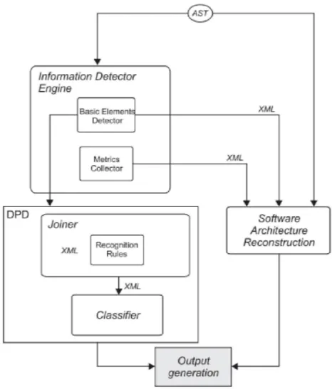
MARPLE stands for Metrics and Architecture Reconstruction plug-in for Eclipse which supports design pattern detection and software architecture construction through the use of basic elements and metrics extracted from the source code. This is one of the state of the art tools for design pattern extraction. The idea of MARPLE is to generate candidate design pattern instances using simple structural query and use a trained classifier to verify if it is an actual design pattern instance.
12
Figure 2.1 The architecture of MARPLE
This approach makes use of the elemental design pattern which is similar to Micro patterns for the design pattern detection. This system requires providing the query pattern to search for as in our case. The novelty of this system is that it makes use of machine learning approach to create an extra module, a classifier, for verifying the correctness of a candidate pattern instance. The design pattern detection involves providing joiner pattern to Joiner module which generates the candidate pattern instances which is verified by the classifier to confirm if it’s a correct design pattern instance [16]. The classifier is generated by using machine learning approach of supervised learning of neural networks. The architecture of MARPLE is shown in the Figure 2.1.
This approach is able to detect any new kind of patterns but for that the classifier needs to be trained which requires a lot of test data. This approach suffers from
13
scalability as the size of the analyzing project increases in size hence a new project called Distributed MARPLE is underway.
2.2.8 Fujaba
Fujaba stands for “From UML to java and back again” which is a tool suite developed at Paderborn University. This is a system to semi automatically detect the pattern instances following an interactive pattern matching which is based on the graph grammar and graph parsing technique combined with fuzzy logic. Fujaba is based on the generation of abstract syntax graph (ASG is a data structure that represents the syntax of a language as a graph).
The brilliant mechanism in Fujaba is that the detection algorithm annotates the identified pattern instance in the abstract syntax graph with the pattern names and roles. The algorithm makes use of that knowledge while detecting the pattern instances. This is called forward/backward chaining (combined bottom-up, top-down) strategy [17]. The bottom up strategy is about processing lower level details whereas top-down strategy is making use of annotations made in the abstract syntax graph for detection. So, the algorithm switches intelligently between forward/backward strategies to detect a pattern instance. The pattern to detect is provided as a graph transformation rules which is applied against the abstract syntax graph of a source code. The Fujaba tool provides a comprehensive user interface where a user can compose new pattern definition as wished. One can define sub patterns as well and make use of that to define another pattern. In order to handle the variant implementation of design patterns, it makes use of the fuzzy logic where one can provide a fuzzy value to a rule to describe its degree of uncertainty.
The main applicability of Fujaba is that, the pattern detection is an interactive process where a reverse engineer can make a decision. While detecting pattern, if the search result contains a lot of false positives or does not result any result then the reverse engineer can change the pattern description through the UI and do the analysis by contracting or relaxing the pattern definition and changing the fuzzy value.
2.2.9 Pinot
PINOT stands for pattern inference and recovery Tool which is based on the structural and behavioral analysis of the source code. This is a fully automated tool for
14
design pattern detection and claims to detect all the GoF patterns. This tool is based on the approach of reclassification of GoF patterns based on the reverse engineering point of view. Based on the structural and behavioral resemblance, the GoF pattern is reclassified into five categories and different strategy is applied to detect the pattern instance in each category[1]. The five categories of reclassification are:
1. Patterns that are already provided in the language
2. Patterns that are driven by structural design and can be detected using static structural analysis
3. Patterns that are driven by behavioral design and can be detected using static behavioral analysis
4. Patterns that are domain specific 5. Patterns that are only generic concepts
The reclassification of the GoF patterns based on above categories is summarized in the Figure 2.2 below. The design patterns are shown in the rectangle; ovals represent the sub-pattern which is building block of design pattern. The label in the edge represents the searching criteria. The patterns without any connection are the ones that is detectable only through static inter-class relationship analysis. The color of the component represent in which category of classification the respective design pattern fall.
The PINOT tool is impressive in performance and accuracy of detecting the pattern instances. The reason behind it is that, the attempt for detecting the design pattern is completely focused on GoF patterns. Moreover, it is built from an IBM java compiler, Jikes, in which it embeds the pattern analysis code thus it makes use of the symbol tables and other tables created by the compiler. But the main drawback of this tool is that the pattern detection is totally hardcoded and thus it is not extendable. Since a design pattern can be implemented in a varying ways so, it is not able to identify every variant of design pattern.
15
Figure 2.2 A Reclassification for Reverse Engineering of the 23 GoF Patterns
2.3 Our Approach
Our approach here is based on reengineering the solution applied to PINOT which uses structural and behavioral analysis of source code. The solution we propose here leverages the potentiality of structural and behavioral analysis for detecting any kind of design pattern as long as the reverse engineers are able to formulate it by providing the structural clues and behavioral analyzers. In our case, the source code is modeled as a graph. The pattern detection engine takes a query pattern to search for as an input and tries to find the pattern instances in the source model and return the instances of sub-graph that matches the query pattern.
The novelty in our approach is the application of incremental graph pattern matching algorithm for building the design pattern detection engine which provides the flexibility to compose the query pattern. The flexibility here means that the pattern detection engine is not dependent on behavioral analyzers and that new analyzers can be created and fed in through query pattern. This makes our system flexible to handle any kind of reverse engineer query as long as it can be formulated as a query pattern. Apart from that our approach decouples the hardcoded logic of static and behavioral analyzers in PINOT which allows the system to be extensible by defining new analyzers as a constraint which does not require any changes to the design pattern detection engine.
Since the behavioral analyzers depend on processing the AST (Abstract syntax tree) which are different in varying programming language hence, we are restricting here to Java Programming language. The approach is described in more detail in chapter 3.
16
Chapter 3 Design Pattern Detection Approach
3.1 Introduction
Design patterns are design solutions to well known problem and the design elements has its own roles and responsibilities which are represented in the source code by class and attributes/methods respectively in the source code. Our approach for design pattern detection here is to allow the user to provide the query to search the pattern as a graph and then get the result back again as a graph which specifies the elements along with their roles and relationships. The algorithm we use here for graph pattern matching is influenced by the incremental graph pattern matching algorithm used in GraphQL[18] which is applied for matching graph patterns in RDBMS. But since in our case we don’t use RDBMS so, we have modified the algorithm for incremental graph pattern matching, where we try to match the graph pattern by moving from one node to another following a single edge at a time.
Regarding the uniqueness of our approach, in all the approaches based on graph matching it has provision for providing constraints at the edge level or node level but doesn’t have an option for providing a constraint at graph level which is included in our case. Moreover, in our case the constraints to be applied at node/edge/graph can be composed to form a complex one by combining two or more constraints which server the purpose similar to Boolean operator like AND and OR.
3.2 Design Pattern Extraction
Our approach here for design pattern detection is based on the structural and behavioral analysis of the source code. For the ease of specifying the structure of the pattern our approach is to model the source code as a graph. For structural analysis, it involves identifying the inter-relationship between classes and for behavioral analysis, we need to define analyzers and include it in the query pattern as a constraint which needs to be satisfied by a candidate instance to be a design pattern instance. The behavior of the
17
analyzer is up to a user to define, so the source code to analyze needs to be represented in an abstract way such that it is accessible to the analyzer.
We have two phases for design pattern extraction viz Static analysis phase and Graph pattern matching. In the static analysis phase, the static facts are extracted from the source code and represented by a directed labeled graph where the class/interface represents the graph node and the directed labeled edges represent the relationship between nodes. In the graph pattern matching phase, the pattern to search for is provided as a search pattern query to the graph searcher engine which returns the pattern instances. The Graph search engine is the core processor that makes use of the source code graph model generated from static analysis phase to search for the pattern instances satisfying the query pattern.
The two major process, static analysis and graph pattern matching, for the design pattern detection is explained in detail below.
3.2.1 Static Analysis
The static analysis of the source code involves the process of extracting static facts from the source code and representing it as a directed labeled graph where a class/interface represents nodes and edge represents the relationship between classes. In this phase, the source code is parsed and represented in an abstract way. The abstracted source code from this step is stored in XML file so that it can be referred later to search for pattern instances. In this phase, the extracted information is processed to identify the inter-class relationships like inheritance, references etc.
3.2.2 Pattern Matching
The pattern matching process involves specifying Query pattern, generating a query plan from the query pattern and applying it to detect the pattern instances using Incremental graph pattern matching algorithm which is the novelty of our approach.
As it is well known by the name “Sub-graph Isomorphism Problem” [19] that determining whether a graph G1 is a sub-graph of a graph G2 is NP-complete hence our approach also suffers from this problem because the pattern matching process involves providing a pattern to match as a query and searching the pattern through the information
18
extracted during the static analysis phase. The query pattern is represented as a graph and also includes the constraints that need to be satisfied by node or edge or the whole graph. 1. Query Pattern
The query pattern is a graph structure formed by dummy nodes which is labeled by roles (as we know in design pattern each elements has a certain role for e.g. AbstractFactory, ConcreteFactor etc) so that the pattern can be represented and related logically. One restriction in the label of roles is that, each role must be unique. The directed labeled edge is used to represent the relationship between the nodes. Moreover, finally when we get the search result, the nodes in the search result are labeled by these role names so that we can easily understand the visual structure of the result. In this Query pattern, we can provide Constraints on each node/edge or whole query pattern that needs to be satisfied. The proper choice of these constraints helps us to determine the proper design pattern instance or to differentiate between patterns that share the same structural clues.
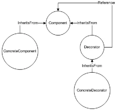
The Figure 3.1 below shows a query pattern for the Decorator design pattern. The diagram only shows the structural clues but the constraints are not shown. The query pattern resembles the UML diagram of a design pattern in structure.
19
2. Query Plan Generation
The Query plan is the plan for detecting the sub-graph in the provided graph satisfying the query pattern. The query plan is a list of constraints that if applied sequentially starting from a node in a graph results out a sub-graph which satisfies the query pattern. Actually it is the breadth first traversal of the nodes in the query pattern where a random node is considered as a root node and all other nodes are traversed. The query plan generation is a process of transforming the query pattern graph into a tree of operations which when followed is satisfied only by the sub graph structure that matches the query pattern. One of the problems for query plan generation is the presence of the cyclic relationship where the child nodes again relate back to the parent node. In order to tackle this cyclic case, we transform the cyclic relation by replacing it with a filtering operation which mentions a constraint that it should have a relation to the parent node by some relationship.
The algorithm for Query plan generation is mentioned below:
1. Initialize an empty list QueryPlanList, ProcessedList and ProcessingQueue whose purpose is mentioned below:
QueryPlanList -> list to hold the operations (QueryPlan) that if satisfied
completely by the vertices of a graph then the search pattern is assumed to be satisfied. QueryPlan mentioned here is relationship between nodes which has the attributes as Left Node, Right Node, RelationShip between them, the direction of relationship (forward if directed from left to right node otherwise backward) and a Boolean attribute mentioning whether it is a filtering operation which is to tackle the cyclic case defined above.
ProcessedList -> list to hold the nodes whose child are already
processed/traversed.
ProcessingQueue -> list to hold the nodes whose child are yet to be
processed/traversed.
2. Pick a node randomly from the search pattern to process and add that node to the ProcessingQueue
20 3. While processingqueue is not empty do 4. {
5. node n1 = get first node in the processing queue and remove it from the head of the queue.
6. for each edge (e) (incoming or outgoing) from the node n1, do 7. {
8. Get the other node related to it in the edge (e), say n2.
9. If n2 is contained in the ProcessedList then continue the loop.
10. Create a QueryPart with n1 as left node, n2 as right node, RelationShip label of edge e as Relationship and the direction as forward if e is directed from n1 to n2 otherwise backward.
11. if n2 already exists in the processing queue then in the QueryPart set filteringtype true otherwise set filteringtype as false and add n2 to the ProcessingQueue.
12. }// End of For Loop 13. Add n1 to processed list 14. } //End of While Loop 15. return queryplanlist;
3. Incremental Graph Pattern Matching
In the Graph pattern matching process, each node in the graph is expanded incrementally following the query plan generated by the above mentioned algorithm. While expanding the node incrementally, if all the relationship in the query plan is satisfied then the then resulting graph is considered to satisfy the search pattern and is included in the search result. The algorithm for pattern matching (SearchGraph) mentioned below is applied to each node in the graph one at a time. This algorithm tries to find every structure that is isomorphic to the query pattern and hence finally we can collect all the subgraph and return as the final search result. Since the algorithm tries to match the query pattern structure and apply the constraints simultaneously during the process of searching hence, most of the infeasible cases are pruned early.
21
One of the optimization we can do here by knowing the fact that most of the design pattern instances involves the inheritance relation is that during the query plan generation, instead of selecting the root node randomly, we can choose the node which involves inheritance relation such that there are some child nodes of that node then, during the graph pattern matching procedure, the nodes which doesnot contain any child node or inheritance relation are pruned in the first step which increases the search speed. This is easily possible by allowing the user to choose the root node while providing the query pattern. This is just as providing query hint in the query as in case of RDBMS. The algorithm for SearchGraph is mentioned below:
SearchGraph(queryplan qplist, GraphNode n1)
1. Initialize empty Graph g and add n1 to Graph g with the role same as the role of the queryplanlist rootnode;
2. return PDWF(g, qplist, 0); //Process Depthwise Further
PDWF(Graph g, QueryPlanList qplist, int cindex) //here PDWF stands for process depthwise further and cindex is current plan execution index in QueryPlanList
1. List<Graph> FinalResult = null;
2. if cindex == qplist.length //all the query plan is satisfied by the graph g 3. {
4. check if the graph level filter is satisfied by g. If success then add g in FinalResult and return FinalResult otherwise return null;
5. }
6. QueryPlan qp = qplist[cindex];
7. node n1 = get the node from g with the role same as the role of the left node in qp;
8. relation r = get the relation from the query plan qp; Edge e = null; 9. If(qp.filteringType) //Current query plan is a filter type
10. {
11. node n2 = get the node from graph g with role of right node in qp;
12. if(n1 and n2 is related by relation r and same relationship direction in qp) 13. {
22
15. FinalResult.addAll(PDWF(g1, qplist, cindex + 1)); 16. }
17. } 18. Else 19. {
20. Apply left node filter in qp to n1, if it fails then return FinalResult;
21. for each node n2 where n2 is the list of nodes related to node n1 by relation r and as per the direction mentioned in query plan qp
22. {
23. if (n2 already exists in graph g OR application of right node filter to n2 fails OR application of edge level filter to the edge between n1 and n2 with relation r and having same relationship direction as mentioned in qp fails) then continue the for loop.
24. Graph g1 = clone graph g and add n2 in g1 with the role as mentioned in query plan; Also, add an edge between n1 and n2 in graph g1 with the relation r and same direction as mentioned in query plan.
25. }
26. FinalResult.addAll(PDWF(g1, qplist, cindex + 1)); 27. }
28. return FinalResult;
3.3 Visualizing Search Result
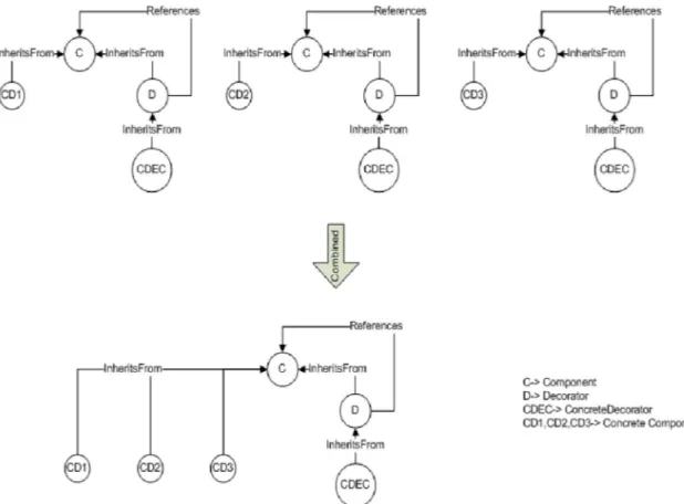
Referring to the pattern query shown in the figure 5 above, the search result returned by the pattern recognition engine will be a number of sub-graphs that is similar to the query pattern in structure. But the problem with this is that in case of decorator pattern, there can be multiple concrete components. Suppose if there was 3 concrete components then it will return 3 sub-graphs as the search result.
23
Figure 3.2 Combining Graph to display Design Pattern instance
In order to have a clear view of the design pattern, we need to combine those 3 sub-graphs to form a single graph so that we can get the clear view of the design pattern. This is shown clearly in the Figure 3.2.
To combine those sub-graphs we apply a mechanism of graph overlaying. In case of graph overlaying, we overlap two graphs that are identical in shape and then compare all the nodes and edges except the node that can vary. If they match, then we can combine those graphs to form a new combined graph. Since in our case, the graphs are all similar in structure so we don’t need to check if they match in structure.
The algorithm followed for graph overlaying is mentioned below which also supports handling multiple nodes multiplicity simultaneously:
1. Input : Two graphs to overlay (say graph g1 and graph g2), The nodes role list which may contain multiplicity (say mlist)
2. Check if all the set of edges in g1 and g2 are equal except the edges containing the nodes with role in the list mlist otherwise return null.
24
4. find the edges in g2 that matches left node role, right node role and edge label with e and add those edges in graph g1 along with the vertices involved in those edges if the vertices does not exist in graph g1
25
Chapter 4 BIGPD Design and Implementation
Based on the approach explained in the previous chapter we have created a prototype called BIGPD (Basic Incremental Graph pattern matching based Pattern Detection). BIGPD, is developed using Java Programming language and Netbeans IDE. The detail of the BIGPD is explained in the following sections.
4.1 BIGPD Design
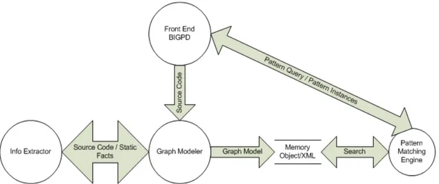
The idea on pattern identification is based on the structural clues matching along with constraints satisfaction. For the design pattern detection, we applied a layered architecture which consists of Static Analyzer, Graph Modeler, Graph Pattern matching engine and Front end system. The Design of the system is shown in Figure 4.1. The task of design pattern extraction involves a workflow of first ingesting the source code, second preparing the graph model for search and the final process is extraction/searching of patterns.
Figure 4.1 Design of Design pattern extraction system
As in Figure 4.1 we have developed information extractor and pattern matching engine as a separate java project producing jar files which is used by the Front end system. The Graph Modeler is a single transformer to model the static facts generated from the information extraction component so, it is included in the Front end itself. The
26
design and implementation detail of each component is explained in the following sections.
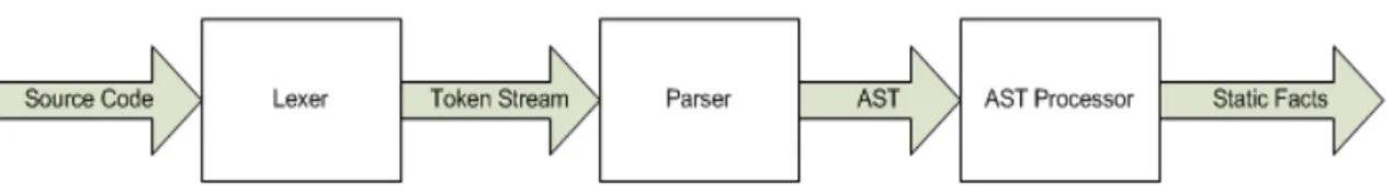
4.2 Information Extractor
This component is responsible for the analysis of source code to extract the relevant information from the source code. The output from this component will be the abstract representation of the source code as AST from which static facts like name of class, methods their arguments, return types, access modifier etc are extracted. An AST is a tree representation of the abstract syntactic structure of source code written in a programming language. An example of an AST representation of a source code is included in Appendix A.
The information extraction of the source is language dependent as different languages have different syntactic structures and semantics. So from the perspective of Compiler Theory, for the process of static analysis we need to have a Lexer and Parser generated from language dependent grammar file which specify the syntactic rules. The Lexer scans the source code file and generates the stream of tokens which is consumed by the parser which checks the correctness of syntactic structure. The parser consumes the stream of tokens from Lexer and generates an AST (Abstract Syntax Tree). After we have the AST, we walk through the tree to extract the facts that we are interested in. The process of facts extraction is depicted in the Figure 4.2.
Figure 4.2 Information Extraction from source code
For the generation of AST from the source code, we have made use of a tool, ANTLR 3 (Another tool for language recognition) V.3.1. ANTLR is a language tool that provides a framework for constructing recognizers, interpreters, compilers, and translators from grammatical descriptions containing actions in a variety of programming languages [20]. Using this tool we constructed Lexer and Parser to process the java
27
source code. The Lexer scans the source code and tokenizes it whereas the parser goes on checking the grammatical syntax and then builds an AST.
After extracting the information, the facts are encapsulated in different objects. The details of the classes which encapsulate the data are listed below:
1. ClassEntity -> Encapsulates the Class/Interface Information (property, method, import, extend/implement, constructur etc).
2. MethodEntity -> Encapsulates the Method Information (argument list, access modifier, return type etc)
3. ImportEntity -> Encapsulates the Import Information (package and class name) 4. AccessModifier -> Encapsulates the AccessModifier (accessor type and other
attribute)
5. ArgumentEntity -> Encapsulates the Argument Information (access modifier, type and name)
6. PropertyEntity -> Encapsulates the property Information (data type, name, access modifier)
The class detail of each of these above classes is included in the Appendix B.
4.3 Graph Modeler
As the Graph Modeler and Graph Search engine are related so we have included them in the same component, GraphSearchLibrary. The graph modeler is the static analyzer component that analyzes the information extracted from the Information Extractor component and generates a graph model. The static analysis phase involves the processing of information extracted by the information extractor component to identify the inter-relationship between classes. In our case we have identified only two relationships, inheritance and references. Inheritance relation is used to represent both extends and implements. References relationship means that a class is referenced somewhere. Currently we have only made use of in memory objects for processing. The AST is stored in the disk as an XML file.
In the labeled graph, each node keeps track of its neighbor and the directed relationship with which it is related to.
28 1. Graph -> this represents a graph
2. IGraphNode -> this is an interface to represent a graph node.
3. Edge<T> -> this is a generic edge which can contain node of any type T.
4. IFilter<T> -> this is a generic interface for a constraint so that user can extend this interface to create new constraints.
The details of these classes are included in Appendix C.
4.4 Graph Pattern Searcher
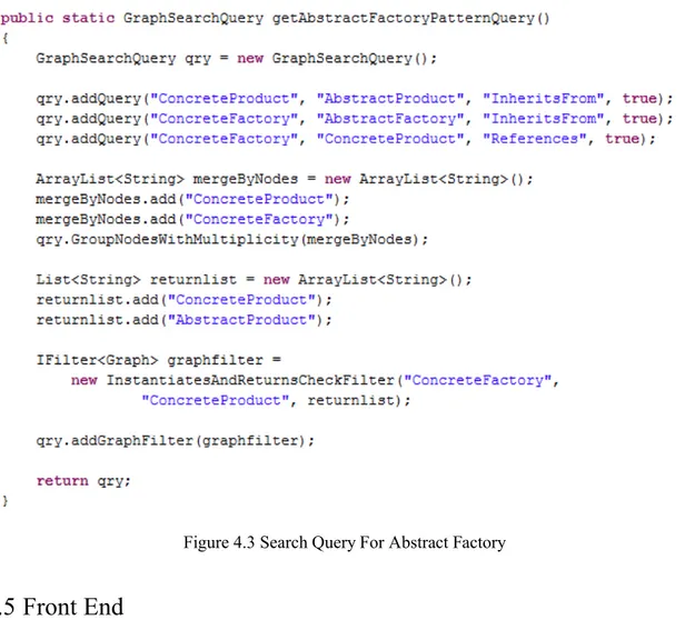
This component is a java library component which is used by the front end system. This component incorporates the algorithm for query plan generation and pattern searching. This component is also responsible for searching through the graph and returning the search result back to the front end. This component provides a public class GraphSearchQuery which is used in the front end to create a design pattern search query. The addQuery method of this class is used to compose a search query. This class also provides method for adding constraint at node/edge or whole graph. For example, a snippet code to create a query for abstract factory design pattern is shown in Figure 4.3.
29
Figure 4.3 Search Query For Abstract Factory
4.5 Front End
This component is the system the user interacts with. This system is responsible for providing the interface for the user to initiate actions and view back the results. Currently this is our simple prototype for just experimentation of our approach, hence the UI is simple with just an option to select the design pattern query and display the search result after searching. Figure 4.4 Shows the GUI of the BIGPD system.
30
Figure 4.4 BIGPD Prototype User Interface
We have made use of the JGraphX component of JGraph for visualizing the search result. JGraphX is an open source java graph visualization and layout component. Before searching for the pattern, we need to pre-process the source folder which can be done by clicking Process Folder button.
The front end system provides graphical interface to select the pattern to query for and view the search result. For the sake of simplicity, currently the front end system does not support to compose the query graphically. We have hardcoded the pattern definition
31
which is invoked based on the pattern selected from the dropdown. Upon clicking the search button the system searches for the pattern selected and display the search result. The search result is listed in the leftmost tree component which we can select to visualize the pattern instance. The search result view of BIGPD is shown in Figure 4.5.
Figure 4.5 Search Result View
In the search result we can see that the rectangular box represents the class/interface and the edge represents the relationship where ‘I’ refer to inherits from and ‘R’ means references. In each rectangular box, we can see a label attached which represents the role of the class in the design pattern.
32
4.6 Composing Complex Constraints
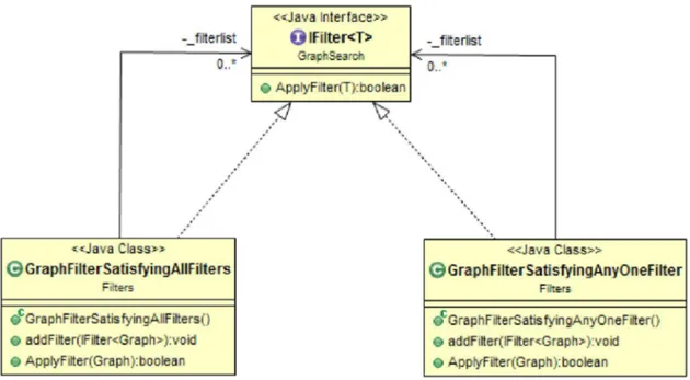
In our approach we had mentioned that we can provide complex composed constraints using Boolean operator AND and OR. In fact we haven’t developed a query language to provide the operator as AND and OR but we have designed internally to support the AND and OR operation. The mechanism of the implementation is described below:
We can see in Figure 4.6 below that there are two specific kinds of Filters called GraphFilterSatisfyingAllFilters and GraphFilterSatisfyingAnyOneFilter which represents ANDing and ORing of filters added to it. We can compose a complex kind of filter by making use of these two filters. Since, each filter that can be added to this two filter is of IFilter type and the type of them is IFilter as well hence one can be added to another as a constituent through addFilter method.
Figure 4.6 Class Diagram of Constraints Design
Example 1: To compose a filter (A AND B) OR C where A, B and C represent a type of IFilter, we can first create an instance of GraphFilterSatisfyingAllFilters say F1 and add A and B to it. After that we can create a GraphFilterSatisfyingAnyOneFilter say F2 and add F1 and C to it and thus F2 is the final required complex constraint.
33
Example 2: To componse a filter ((A AND B) OR (C AND D)) OR (E OR F) where A,B,C,D,E and F represent a type of IFilter, we can first create an two instance of GraphFilterSatisfyingAllFilters say F1 and F2 and add A,B to F1 and C,D to F2. After that, we can create two instance of GraphFilterSatisfyingAnyOneFilter say F3 and F4 and add F1,F2 to F3 and add E,F to F4. Now we can create a final instance of GraphFilterSatisfyingAnyOneFilter say F and add F3 and F4 to it to form the final filter which represents the final complex filter.
Similarly, we can form any kind of complex constraints by composing a Filter using those two available filters.
34
Chapter 5 Experimentation and Result Analysis
As we have already described our approach and have implemented a tool based on that so, this chapter here provides the detail on the experimentation on the tool. Our target here is to show that our tool achieves the objectives it promises i.e. overcome the problem identified in the PINOT tool. For this purpose, we have performed two different studies which are explained in the following sections.
5.1 Design Pattern Detection
To show our approach is able to detect pattern instances, we focused our studies on few of the GoF design patterns viz. Abstract Factory, Singleton, Decorator, Observer, Strategy, Composite and Chain of Responsibility. Since there is no any published benchmark data for comparing the accuracy of a tool in design pattern detection so, we compared our result with the result of PINOT while processing JHotDraw 6.0 Source code.
The result of the pattern instances identified by BIGPD along with PINOT is summarized in the Table 1 below.
Table 1 Design Pattern Detection Result
Design Pattern PINOT BIGPD
Abstract Factory 5 11 Singleton 0 0 Decorator 5 9 Observer 9 36 Strategy 51 83 Composite 4 17 Chain of Responsibility 5 12
35
5.1.1 Result Analysis
It is pretty evident from the result summarized in the Table 1 that our tool produced lot more design pattern instances compared to PINOT. On analyzing the result more closely, we identified that in case of BIGPD, there were no any false negatives but there were inclusion of false positives. On our analysis we figured out some of the causes for the difference in number which is mentioned below
1. The query used in case of PINOT and BIGPD are not identical
We created our own query to detect the pattern instance which could not be equivalent to the PINOT analysis. Though the source code of PINOT was available but we could not find any documentation for the tool. The tool makes use of jikes compiler for java and has modified to do the AST processing so, it was bit complex. We couldn’t decide the criteria for the equivalent query. Though this is one of the reasons for the inclusion of false positives in the result but our assumption is that the result can be further refined by more restricting the constraints on the query to identify the patterns.
2. No communication between constraints
One of the limitations that we found out in our approach was, though we thought of composing constraints to achieve a complex constraint that could be a new behavioral analyzer but the missing piece was those constituent constraints couldn’t communicate and influence each other. The result from the child component couldn’t be fed to the parent constraints. For e.g. consider the case of Abstract Factory pattern. In BIGPD we could just check if there exists a factory method but we couldn’t do any further analysis on the specific identified factory method because the constraints could not communicate and send back the information about which method was identified as factory method. The solution for this problem is out of the scope for now but this can be considered as one of the future works.
5.2 Identifying variant of design pattern
The other point we mentioned about our approach is that the tool can be extended to identify variant of design patterns without making any change to the pattern detection engine. To prove this case, we have taken singleton pattern for analysis.
36
In the Figure 5.1 below, we can see that the code satisfies the structural clue of singleton pattern i.e. it has got a static self member instance, a private constructor and a static method that returns the self member instance “theSpoon”. But this is not an actual singleton pattern because the main intent of singleton pattern is the lazy instantiation of an instance i.e. to return an existing instance if present otherwise create a new instance and return it. But from the code in Figure 5.1, we cannot find any instantiation logic.
Figure 5.1 Invalid Singleton Pattern Code
To make the above code a true singleton we need to add instantiation logic which is shown in the Figure 5.2 and Figure 5.3 below. These two pieces of code represent singleton pattern but the logic involved in instantiation is different. In the first code the guard statement checks if the theSpoon is null, if so then it creates an instance and returns. But in the second code it directly returns theSpoon if it is not null, otherwise creates a new instance and returns. Hence in order to identify both instances of singleton variants, we need to be able to do two different behavioral analyses.
Figure 5.2 Singleton Pattern
37
So, in order to handle this scenario where the first should not be detected as a singleton pattern instance and both the later examples which are variant of singleton pattern should be detected as correct pattern. To achieve this, we extended the system to have two new constraints of type IFilter<T>. In the first constraint we added the logic to check the first scenario where there is object creation involved inside the null check guard statement. In the second constraint we added the logic to check the second scenario where there is return involved inside the not null guard statement followed by instance creation and return.
Finally we created an instance of “GraphFiltersSatisfyingAnyOneFilters” constraint and added those two constraints above as its constituent constraint and applied it at the graph level to the singleton pattern query. This query resulted in the two correct instance of singleton pattern.
Similarly if there is some other new variant of singleton pattern as well then we can create a new constraint implementing the logic involved and add it as well as a constituent. Alternatively, one can write two or more different pattern query and search independently as well.
5.3 Inference
From the positive results of above two case studies we can see the potentiality of our approach and its applicability. It really improves the usability of the PINOT approach which was restricted because of its design. There are some short comings in BIGPD as well but it can be improved further. Furthermore, the platform can be extended further in future in static analysis phase to extract more useful information to make a more richer graph model so that it’s easy to create new behavioral analyzers.
38
Chapter 6 Conclusion and Future works
6.1 Conclusion
In this thesis we identified two problems about extendibility and robustness in the approach of PINOT and proposed a solution addressing those issues. Those problems limited the ability of structural and behavioral analysis approach for design pattern detection. One obvious downside of the proposed solution is the degradation in performance. But the good side is that it stretches the potentiality of the structural and behavioral analysis for the design pattern detection. It provides room for handling varying implementation of design patterns and any other proprietary patterns. This is proved by the experimental results mentioned in the Chapter-5.
Finally, we conclude by saying though the solution mentioned here is not a silver bullet for design pattern detection but the approach is promising based on the extendibility of the system which provides room for evolving.
6.2 Future Works
One of the imminent future works is to fix the limitation of BIGPD, which we found in chapter 5 while analyzing the result, of not being able to have a communication mechanism between constraints. Furthermore, In our approach we mentioned that we can compose a user defined query based on constraints selection but this is not reflected in the prototype we developed so, the front end system needs to support this to improve its usability.
Other possible future works is to optimize the pattern matching algorithm. One of the optimization is tagging of nodes to mark the positive or negative result of applying a constraint on a node or edge so that each time we don’t need to run the same constraint again. Moreover to make the extraction process more comprehensive more research needs to be done for the implementation of a new constraint for behavioral analyzers. Currently the behavioral analyzers are a precompiled java classes. Later on this can be
39
changed to auto generation of analyzers based on some rules defined, so that analyzers can be created during the runtime.
Currently BIGPD is only able to detect patterns in Java source code, so extending this to make it language independent is one of the area of future work. Instead of having varying AST from different programming language, a Meta model needs to be defined to represent AST so that, the design pattern detection can be made language independent.