School of Innovation Design and Engineering
Västerås, Sweden
Thesis for the Degree of Master of Science in Engineering
-Intelligent Embedded System 30.0 credits
MODELLING AND ANALYSING
COLLABORATING HEAVY
MACHINES
Jayasoorya Jayanthi Surendran Nair
jjr15001@student.mdh.se
Examiner: Cristina Seceneleau
Mälardalen University, Västerås, Sweden
Supervisor 1: Stephan Baumgart,
Volvo CE, Eskilstuna
Supervisor 2: Marjan Sirjani
Mälardalen University, Västerås, Sweden
Acknowledgements
I would like to express my heartfelt thanks to my supervisors, Mr.Stephan Baumgart and Prof.Marjan Sirjani for their continuous support during this thesis work. Their patience, motivation, knowl-edge and guidance have helped me in the succession of best results and also in my own personal development. I am thankful to my Co-supervisor Dr. Ali Jafari for his suggestions and advice. I also want to thank my examiner Prof. Cristina Seceneleau, who gave me useful suggestions in the thesis report.
I am grateful for having the opportunity to perform my master thesis at Volvo Construction Equipment. I want to thank the colleagues from System Architecture Department and Electric Site development team for their help and kindness. A special thanks to Mr.Ted Samuelsson, for spending his time to clarify and answer my questions. I wish them all the best for their future work. I would like to express my thankfulness to Mr.Stephan again, for giving me this opportunity to conduct my thesis work under his supervision. His suggestions and comments has helped a lot to improved the whole work.
I also want to give special thanks to my parents and my in-laws for always believing in me, offering their most caring support and enthusiasm.
Finally and most importantly, I would like to express my gratitude and love to my husband Ajesh and our little daughter Aishwarya. Their company, hugs, and unconditional support have strengthened me through this challenging experience.
Abstract
Cyber Physical Systems (CPS) consist of embedded computers and networks for controlling and monitoring the physical processes associated with it. In practice, these systems are complex in nature. Also most of the CPS systems handle concurrent and real time operations and they are mostly distributed in architecture. Suitable analysis techniques need to be used in order to design and develop a CPS system. Formal verification is a branch of software engineering which is used to verify the correctness of a design. Model checking is one technique used in formal verification, where a formal model of the real system is developed. This model is used for verify the correctness of the system design against its specified requirements. For model checking, a formal model and a formal specification language is required. There are several formalism available to represent concurrent distributed systems such as Petrinets, Actor models etc. Actor models are suitable for modeling the functional behaviour of distributed and asynchronous systems. If formal verification support could be incorporated with an actor model, it shall be beneficial in analyzing cyber physical systems. In this thesis, we use an actor based modelling language which is supported by formal semantics to analyze a complex cyber physical system. This study aims to analyze the distributed nature and concurrent behaviour of the system and not timing constraints. The system selected for this study is a safety critical system which consists of several autonomous machines which are operating in a fleet manner carrying out concurrent operations at a site. We also analyze the distributed design architecture of autonomous machine individually. The design implementation of the system is developed in a Robot Operating System and the actor based modelling language used for developing the models is ’Reactive Objects Language’ (Rebeca). Thus major tasks of the study include understanding the ROS based system, transformation of ROS elements to Rebeca models and verification of system specific properties. The study outcomes include identification of few mapping patterns between ROS and Rebeca. During this process a reusable algorithm describing the procedure of transforming any ROS code to Rebeca model was developed. Our study results hence proves the potential of Rebeca in verifying real robotic applications.
Table of Contents
1 Introduction 6
1.1 Thesis Motivation (Problem) . . . 6
1.1.1 Project Definition (Solution) . . . 7
1.2 Research Questions . . . 8
1.3 Research Methodology . . . 9
1.4 Contributions . . . 10
1.5 Report Overview . . . 10
2 Background and Related Works 11 2.1 Distributed Design Architecture of Autonomous Vehicles . . . 11
2.2 Robot Operating System . . . 13
2.3 Formal Methods . . . 14
2.4 Rebeca . . . 17
2.5 Rebeca Model Checker Tools . . . 18
2.5.1 Rebeca Model Checker (RMC) . . . 18
2.5.2 Afra . . . 18
2.6 Related Works . . . 19
2.6.1 Formal verification on Robotic systems . . . 19
2.6.2 System Analysis Using Actor Based Modelling . . . 20
3 ROS to Rebeca Mapping 22 3.1 Understanding HX system ROS source code . . . 22
3.2 Approach to the Model Development . . . 24
3.3 Model Development of HX system design architecture . . . 26
3.4 Evaluation of Properties and their Results . . . 29
3.4.1 Properties of Server Model . . . 29
3.4.2 Verification Results of Server Model Properties . . . 30
3.4.3 Discussion on Server Properties . . . 32
3.4.4 Properties of Machine Model . . . 34
3.4.5 Verification Results of Machine Level Properties . . . 35
3.4.6 Discussion on Machine Properties . . . 36
3.5 Pattern Mapping from ROS to Rebeca . . . 38
3.5.1 ROS Nodes . . . 38
3.5.2 ROS Message Passing . . . 38
3.5.3 ROS Variables . . . 39
3.5.4 ROS Distributed Parameter System . . . 40
3.5.5 ROS member Functions . . . 41
3.5.6 ROS shared Variables . . . 41
3.5.7 ROS Bags . . . 43
3.5.8 ROS Display functions . . . 43
3.5.9 ROS Services . . . 43
3.5.10 ROS Topics . . . 47
3.5.11 ROS Parameter Server . . . 49
3.6 A Pseudo Code for transforming ROS code to Rebeca Model . . . 50
3.6.1 Pseudo code Description . . . 51
4 Electric Site Fleet Management Operation 54 4.1 Understanding Electric Site Case study . . . 54
4.2 Abstracted Fleet Management Prototype . . . 55
4.3 Timed Rebeca Model of Fleet management Prototype . . . 56
5 Conclusion and Future Work 60 5.1 Summary . . . 60 5.2 Discussion . . . 60 5.3 Future Work . . . 61 5.4 Validity Threat . . . 61 References 65
List of Figures
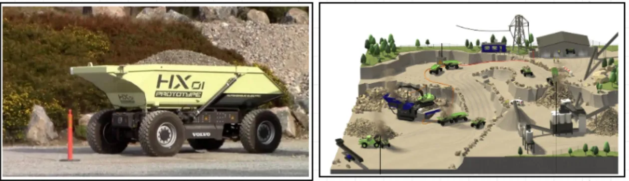
1 Left figure: Volvo’s HX autonomous Hauler, Right figure: Electric Site Fleet
Man-agement Prototype . . . 8
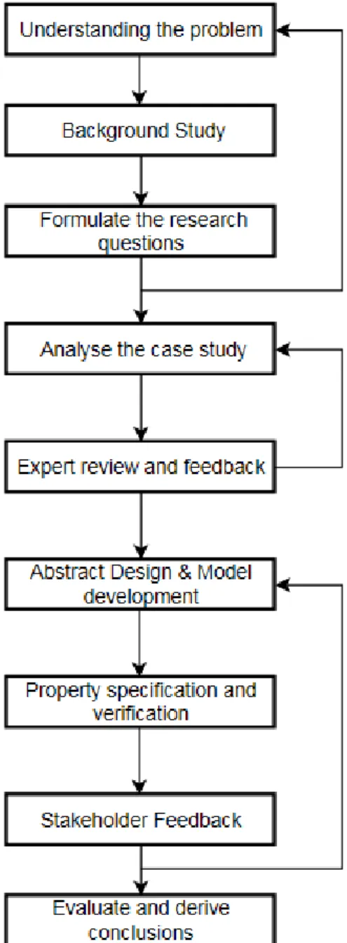
2 Research Methodology Used . . . 9
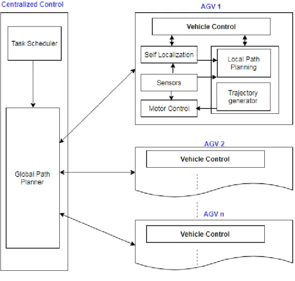
3 A Generalized AGV architecture . . . 12
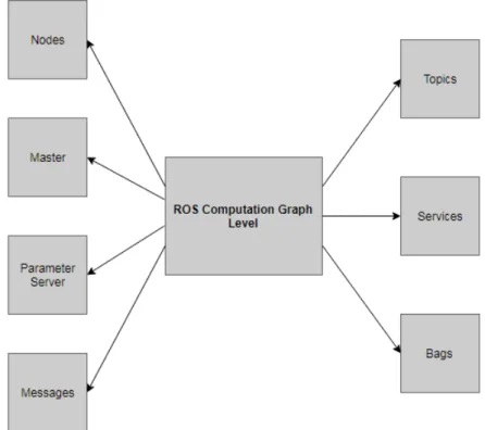
4 An overview of ROS computation level . . . 14
5 An overview of Verification Techniques . . . 15
6 Model Checking Process . . . 17
7 A typical class definition in Rebeca[1] . . . 19
8 High Level software design architecture . . . 23
9 An overview of procedure followed for mapping process . . . 25
10 Representation of System model . . . 26
11 Server Actor Model Representation . . . 28
12 Actor model for Machine Level Model . . . 28
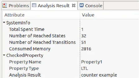
13 Verification Result of Property 1 . . . 31
14 Verification Result of Property 2 . . . 31
15 Verification Result of Property 3 . . . 32
16 Verification Result of Property 1 against fault Injection model . . . 32
17 Verification Result of Property 2 against fault Injection model . . . 33
18 Verification Result of Property 3 against fault Injection model . . . 33
19 Verification Result of Property 4 . . . 35
20 Verification Result of Property 5 . . . 36
21 Verification Result of Property 6 . . . 36
22 Verification Result of Property 4 against fault Injection model . . . 37
23 Verification Result of Property 5 against fault Injection model . . . 37
24 Verification Result of Property 6 against fault Injection model . . . 38
25 Mapping of ROS Node to Rebeca Actor . . . 39
26 Mapping of ROS Message Passing to Rebeca KnownRebecs & Message Servers . . 40
27 Mapping of ROS local variables to Rebeca statevariables . . . 41
28 Mapping of ROS parameter system to Rebeca Environmental Variable . . . 42
29 Mapping of ROS member function to Rebeca message server . . . 42
30 Pattern Mapping for ROS Service Mechanism . . . 46
31 Pattern Mapping for ROS Publish-Subscribe Mechanism . . . 50
32 An overview of Mapping Patterns between ROS and Rebeca . . . 53
33 An Overview of Fleet Management Model Development . . . 54
34 Fleet Operation Prototype . . . 55
35 Fleet Path for Operation Procedure . . . 56
1
Introduction
1.1 Thesis Motivation (Problem)
“Cyber-Physical Systems (CPS) are integration of computation with physical processes” [2]. Phys-ical processes can be wireless sensor networks, Internet of Things etc. which requires monitoring and control using embedded computers. Major applications of CPS include traffic control and safety, advanced automotive systems, avionics, critical infrastructure control, distributed robotics and so on. Most of these systems are distributed real time in nature, with integrated sensors and actuators which can manipulate the nature of interactions. Also “Cyber-physical systems by nature will be concurrent” [2]. Concurrent systems have timing dependency which is crucial and any small variation of that can lead to bigger consequences. Also one failure in concurrent systems could be contagious and spread across the system. This could lead to large-scale catastrophic fail-ure triggered even by a small mistake. One typical example for this scenario is the ’2003 blackout incident’ in North-Eastern United States [3]. Due to an outage of a single transmission element of electricity generation, the parallel transmission paths become overloaded and this overloading cascaded to a condition where electricity production and distribution for the entire city was jeop-ardized. The source reason of outage in single transmission element can occurs due to various unnoticed factors such as aging of equipment, mis-operation of a protective device or even envi-ronmental factors. If proper control actions are not taken, such events can cascade easily and can result in catastrophe. Thus, CPS system maintains a higher degree of coordination between physi-cal and computational elements and this factor introduces safety and reliability requirements when compared to general purpose computing. “The economic and societal potential of such systems is vastly greater than what has been realized and major investments are being made worldwide to develop the technology”[2].
For developing CPS, we need to select out a suitable technique to analyze the system and its end-requirements. CPS analysis requires focus on its distributed architecture, real time constraints and concurrent nature. However, this thesis focuses in analyzing and verifying only the distributed and concurrent nature of CPS systems, but not on to their timing or interaction between physical and software components. There are a wide range of analysis techniques such as testing, simulation, assertion check, formal verification methods and model checking. It needs to be assured that the developed system is inline with expected requirements. Anyhow the selected analysis technique shall be able to manage the complex behaviour of CPS system using levels of abstraction. As the complexity increases, reliability assurance requires inexorable testing. Also most of these systems are designed to be operated over a longer period of time under several environmental conditions and thus scope of testing becomes extremely large. Similarly simulation testing are effective at de-tecting an error quickly and easily, but when it comes to complex systems it is not time effective.[4]. “Formal specification and verification, an alternative approach which guarantees that the require-ments or the desired properties are satisfied for any possible execution of the system, have therefore been active areas of research in the distributed system community for more than thirty years.”[5].
Formal verification is a field of software engineering, where correctness of a design or algorithm can be verified against its end requirements or properties using mathematical proofs. Model Checking is one approach in formal verification method. A formal model could help in both qualitative and quantitative analysis of system development without considering its implementation details. Significance of model checking is that, it verifies for system state at least once. There exists several model checking tools such as UPPAAL, SPIN, PRISM, Java Pathfinder etc. which are based on modelling languages such as Timed Automata, PROMELA, PEPA/Plain MC, Java and so on. Actor based modelling is another concept for modelling concurrent systems. This too is a mathe-matical model, where actors are basic entities of concurrently executing objects that communicate exclusively via asynchronous messages[6]. Actor models have lesser semantic gap between formal verification approaches and real applications. As engineers this modelling approach shall be easier and more convenient to use. Thus, a combination of actor model and formal verification method shall be a suitable technique to analyze a distributed concurrent CPS system. Reactive Objects Language (Rebeca) is an actor based modelling language, which is supported by formal methods
and tools. Rebeca models shall be translated into existing model checker languages using ’Rebeca verifier tool’ so as to enable property verification using the models. Modular verification and ab-straction techniques are used to reduce the state space and makes it possible to verify complicated reactive system.” [7]
1.1.1 Project Definition (Solution)
The goal of this thesis can be defined as an analysis study of a distributed concurrent cyber physical system, using an actor based formal modelling language. We have selected a case study of ’Electric Site Project’ with Volvo Construction Equipment. The scope of this project includes developing autonomous machines for material transport for an electrified quarry site. These machines are designed to operate in a fleet manner. Currently these are machine prototypes with a carrying ca-pacity of 15 tons and are completely battery driven. They are designed for loading, unloading and charging in a cyclic manner. The machines are designed to operate autonomously and coordinated by a centralized server control. These machines are termed as ’HX prototype hauler’ and they fall under the category of CPS systems. Also they are safety critical systems, since the failure of a system could lead to consequences that are determined to be unacceptable[8]. Similarly the site operation, termed as ’Fleet Management Operation’ consists of several concurrent processes and in-terdependent operations forms a CPS system. Hence the aim of this study is to analyze distributed nature of HX prototype machines and concurrent behaviour of Fleet Management Operation using Rebeca actor modelling language. Fig1 shows HX autonomous hauler and an overview of Fleet Operation at Electric Site.
The design of HX machine software and fleet management prototype are developed in a robotic framework termed as ’Robot Operating System(ROS)’. “ROS is a framework for writing robot soft-ware. It is a collection of tools, libraries, and conventions that aim to simplify the task of creating complex and robust robot behavior across a wide variety of robotic platforms”[9].ROS provides all essentials for developing robotic applications as a complete package. Thus, in order to achieve our thesis goal, the ROS code of HX machine design has to be analyzed and it shall be transformed to or represented as Rebeca actor models. Modelling of fleet management prototype is based on the inputs from experts at the organization and it does not require ROS to Rebeca mapping process. Hence a major work in this thesis is to develop a true model of the real electric site system. This process foresees few challenges which are described as follows. Firstly developing an actor model of a ROS based system involves reverse mapping of robotic components to actor models. Mapping of robotic components to actor models involve potential inconsistencies which needs to be solved. The inconsistencies are due to the differences in framework terminologies between ROS and Rebeca. In order to solve this problem, relevant ROS components have to to be identified and they have to be functionally transformed to corresponding Rebeca representation. Nevertheless, it is expected that components that cannot be potentially transformed from ROS to an actor rep-resentation have to be properly abstracted, without abstracting significant functional details. On the other hand, attempting for a complete and direct transformation of the ROS based system to actor model can lead to a condition where the state space generated by model execution grows ex-ponentially, resulting in a scenario termed ’state space explosion’, which makes the model checking process unusable. The success of model checking and verification solely depends on the quality of the developed model, whether the model truly represents all the required functionalities and has specified required properties to be verified. Therefore while abstracting the real system, modelling must be done in such a way that it captures crucial features, parameters and constraints of the real system while avoiding a state space explosion.
Figure 1: Left figure: Volvo’s HX autonomous Hauler, Right figure: Electric Site Fleet Management Prototype
1.2
Research Questions
In this section, we describe the questions that are aimed to be answered by the end of this study. Considering the points presented in1.1, three questions are defined as the research questions at the start of the study. The questions are defined from different phases of this research, which are listed as below.
RQ1: How can ROS code be mapped to Rebeca model automatically?
This question focuses on the process of automating ROS code transformation to Rebeca model. Since there are foreseen challenges in this process, the aim is to develop a specific algorithm or procedure with which this mapping could be done without much complication. The answer for this question shows a possibility for extending this study to one further level where, ROS code for Electric Site system can be directly mapped to Rebeca model.
RQ2: What are the challenges involved while reverse mapping a robotic system to an actor based formal model?
One of the main challenge involved in developing a formal model of a robotic system is that the systems are complex in architecture. They shall be various tasks of varying priorities within the system. Thus, it is a not an easy task to combine them to a single representation. Also due to nu-merous state transitions and computations, the developed model can result in a huge state space while verifying it. Such inconsistencies that are encountered while reverse-mapping the robotic source code to an an actor-based model need to be properly handled.
RQ3: What are the properties that can be derived and possibly to be verified using Rebeca models?
The properties are usually certain requirements of the system that have to be satisfied under any conditions. A satisfied property from model checking verification assures that the system might also also satisfy that particular property. Thus, this question focuses to identify relevant and obligatory requirements of the system and get it verified using Rebeca models.
1.3 Research Methodology
This section includes the research method used for addressing the above research questions. This section includes the research method used for addressing the above research questions. We used a multimethodological approach introduced presented by Nunamaker et.al[10] in 1990, as a reference for developing research method suitable for this study. He defines four main phases for this ap-proach Theory Building, System Development, Observation and Experimentation. We expanded each of the phase in such a way that back iterations are allowed within every phase. Figure2shows step by step details of research methodology used in this thesis work.
Figure 2: Research Methodology Used
The initial step was to conduct understand the problem. This was done by conducting a background study related to the context. It was then followed by defining research questions, which helped to shape up the thesis. This set of process was iterated and more clarity was
obtained in understanding the thesis. Based on the above knowledge and with the reference of selected case study, an initial analysis was made with respect to certain include and exclude criteria. The analysis outcomes were used for developing abstract system design and further to develop the models. Design system requirements are specified as properties and they are verified against the system models. Now based on the feedback and review comments from stakeholders, the system development phase was iterated with several rounds of experimentation. This helped to fine tuning of verification process. Lastly the models are evaluate and conclusions are derived out of it. The results are documented in the report.
1.4
Contributions
This section presents major contributions of this thesis study, in solving the problem described in Section1.1. The major contributions out from this study are as listed below:
• Mapping Patterns from ROS to Rebeca
A major part of this thesis is to transform ROS code to Rebeca models and to verify system specific properties using the developed models. This process resulted in connecting Rebeca semantics to corresponding ROS terminologies. Thus, a list of mapping patterns between ROS and Rebeca were derived at the end of the study.
• An algorithm for automating ROS to Rebeca Mapping Process
While deriving the mapping patterns between ROS and Rebeca, we also identified a standard procedure to develop these mappings. We structured the procedure as an algorithm which can be applied on any ROS code for transforming to Rebeca model.
• Identification of relevant properties and their verification
This is a stand-alone contribution for this particular case study. We identified certain system specific properties which were identified while understanding the system design and also found to be relevant properties while referred to other similar studies.
1.5
Report Overview
An overview of this report structure can be explained as below:
• Chapter 2 includes ’Background’ information and ’Related Works’ for the thesis. This chapter gives a prerequisite knowledge about the topics dealt with the study and state of the art for this title.
• Chapter 3 presents ’ROS to Rebeca Mapping Process’. This chapter includes description on HX hauler case study, analysis of ROS code, Model development of HX system and property evaluation. This chapter also includes a list of identified ’Mapping Patterns from ROS to Rebeca’ and an algorithm for the automatic mapping of any ROS code to Rebeca models. • Chapter 4 presents ’Fleet Management Operation’ prototype description and model
develop-ment. This chapter also includes model checking of properties of this prototype model and their results.
• Chapter 5 is the final section in this report under the title ’Conclusion’ and it includes a summary, discussion and possible future works for this thesis.
2
Background and Related Works
In this section, we present an essence of background study conducted during the initial phase of research. Since this study touches a number of areas, such as Formal verification, actor based modelling, ROS framework etc. this section is divided into short subsection. A brief explanation required to understand each of this topics are included under each subsection. The state-of-art of this topic is also included at the end of this section.
2.1
Distributed Design Architecture of Autonomous Vehicles
The systems that we are dealing within this study are autonomous vehicles/machines which have a distributed design architectures. Background studies show that, this design architectures are used for most of the automated vehicles which are termed as ’Automated Guided vehicles(AGVs)’. “AGVs are cyber physical systems, with autonomous interacting units equipped with sensors and actuators to interact with their environment and to allow them to be intelligent, cooperative, and communicative”[11]. These systems has sensors for perceiving its environment conditions and this information is used to compute and take decisions for the action to be taken and finally responds using actuators. They are generally used for industrial applications such as materials handling systems, manufacturing or construction systems and so forth[12]. In most of the cases, they shall be operating in a fleet manner where several AGVs operates together by interacting with each other[12]. In this case, they are not 100% autonomous, there exist a central control system which helps to coordinate between them and to supervise the entire process [12]. This refers to a distributed architecture of AGV systems. A wireless LAN could be used in order to provide un-interrupted communication within the AGV system’s distributed software. Also the prime focus while designing AGV systems would be to develop a control system which enables path routing, collision free navigation, obstacle avoidance, battery management, no deadline misses and no dead-lock conditions [13]. Several algorithms have been developed for motion planning strategies for these machines to cope with open environments and to reach final destination. In addition to this reliability and safety has to be ensured while designing such systems, as any negligence can lead to bigger consequences. David González et.al states that “Despite of some remarkable results obtained up to now, there is still a long way to go before having fully automated vehicles on public roads, including technical and legal unsolved challenges” [14].
In practice, software design used for any AGV design architecture is distributed in nature[15]. A overview of general AGV control system is shown in Figure3[12]. In this architecture, a supervisory control is located at the server side and it schedules job priorities and assigns individual machine tasks. Also a global route planner routes path segments for all the machines within the operating site. Now this paths segments shall be distributed to every machines in the fleet. At machine level, individual control system is located for each AGV. It consist of sensors which shall perceive envi-ronmental data and helps in self localizing the machines. This helps in avoiding obstacles and local paths shall be calculated and this information is sent to actuator controls. Each request driven from server shall be distributed as internal processes for each machine. Therefore in AGV system it is required to have an internal co ordination as well. This helps to track vehicles each other, there by avoiding collisions between them and also to avoid any deadlock condition. This struc-ture of distributed software control system is the base for any AGV with modifications as per their application and they provides flexibility, space utilization, safety and operational cost efficiency. Industries demands for flexible, cost effective and less maintenance demanding solutions[12]. This can be achieved only with a distributed system, however it increases the complexity[12]. Thus, it is a challenge to find the right balance[12].
Moving on to design algorithms, there exists several navigation strategies and routing algorithms for AGVs. AGVs can be considered as a ’Multi Agent System’, where several agents are closely coupled to work together[15]. “The main functionalities that an AGV transport system has to fulfill is assigning incoming transport tasks to appropriate AGVs, routing the AGVs through the warehouse efficiently while avoiding collisions and deadlocks, and maintaining the AGVs batteries” [16].Thus, the major focuses in AGV system design and development are selection of right routing
algorithms, localization techniques, obstacle avoidance strategies and ensuring a collision free navi-gation. The navigatory tracks are usually predefined and is used for global path planning at server end. However, based on sensory inputs and perceived environmental information, local path has to be computed and updated frequently. Kalman Filter Localization algorithm (KFL)/ Extended KFL algorithm or Marklov algorithm and Monte Carlo algorithms etc. are the most preferred ones for computation of self localization in AGVs. Similarly path planning algorithms such as Di-jkstra’s algorithm, state lattices or Adjacent matrix method are quite popular ones to this end [14].
Being said that, AGVs are still associated with challenges when it comes to real time planning computations[14]. “The limited time for generating a new free collision trajectory with multiple dynamic obstacles is an unsolved challenge” [14]. Even though it is less expensive to use distributed control algorithms than a high performance computer, they are time consuming and are at a risk of not meeting with timing constraints. Also there exists certain ambiguity in perception and con-trol constraints. Researches has been conducted in this area to properly handle ambiguities with perceived information and thus to develop a better real time environment knowledge[17]. One such study is presented by Gianluca Antonini and Michel Beierlaire in 2005[17]. More recent develop-ment involves human factor, a driver who can interact with the system through Human Machine Interface (HMI)[18]. However it creates newer challenges such as sensor fusion uncertainties, driver knowledge etc. for generating safety navigation.
2.2 Robot Operating System
Robot Operating System (ROS) is a licensed, open source middle-ware framework for developing robotic applications and is becoming a de facto standard in this area[19]. ROS allows service oriented communication between the network components. It also supports hardware abstraction, device drivers, libraries, visualizers, message-passing, package management etc. and thus aids a developer with low level coding requirements for developing robotic systems[19]. Furthermore, end to end software debugging is supported in ROS with the full source code of ROS being publicly available. This acts as a complete reference for the developers and it is a community where they too can contribute[20]. ROS framework development was started with STandford AI Robot (STAIR) project. and later in 2007 further established at Willow Garage as open source distributed software under Berkeley Standard Distribution License (BSD). Recently ROS infrastructure management was taken over by Source Robotics Foundation 6 (OSRF)[20]. ROS is not a real time operating system, but with its rich features and multilingual programming convenience made its popularity to grow tremendously and it has integrated with numerous development platforms such as Matlab, Ardunio, Android, Labview etc[21].
The fundamental processing units in ROS are called ’Nodes’. A node is designed to perform specific tasks such as publishing data, acquisition of data, data computation etc[9]. Node names shall be unique and all the nodes are registered to a ’Master node’, which keeps track of all the nodes in the network. This helps to establish peer to peer communication among nodes and helps to find each other. Nodes, libraries, configuration files and all other dependent element for a function forms a ROS package[9]. All data communication occurs in form of ROS messages. Thus, a ROS package structures the network functionalities in a ROS system. There are several ways by which communication occurs in ROS system, majorly via Topics and Services. Topics are means of communication by which message transfer occurs by a publish-subscribe scheme.
Communication through topics is the most basic protocol used in ROS framework[9]. Topics are unique channels, designed for unidirectional data flow through which nodes exchange ROS mes-sages. They have special semantics which separates the source information from its reception. A ’Topic’ can be considered as a named channel or bus. A node which is sending out messages publishes it to the topic. Similarly the node which receives the message has to subscribe to that particular topic in order to access the published data[9]. One topic can be used by several nodes to publish their data, also multiple subscribers can access the same topic as well. On the other hand services offer communication through request-reply scheme. That means a node can offer or serve services under a specific service name and the client node can avail the service by sending a request. As soon as the service is available the server node shall reply to the client node.
Services is defined by a pair of messages: one for request and other for reply. Another commu-nication form is called ROS Bags of store-retrieve scheme and it uses a remote procedure call (RPC) protocol which runs inside ROS master[9]. This means that the functions or procedures used by these parameter servers are accessible through normal RPC libraries. It shall be in a shared location accessible via network. Information can be stored during run-time, and it is later retrieved to playback. For example, sensor data or continuous key inputs can be stored when it is processing and later to check its behaviour, it can be retrieved and analyzed. Parameter Server in ROS can store data of various data types and it helps to manipulate required parameters for a ROS system[9]. Figure4 shows an overview of ROS computational level.
Despite of numerous possibilities and advantages of using ROS framework, there is no widely ac-cepted solution to review or verify ROS operating system.However, several approaches like run time monitoring, static analysis techniques, model checking etc. exist have been proposed to achieve this[22].Colin Angle, co-founder and CEO of iRobot states that unless it is made stable and secure, ROS cannot be used for critical solutions such as military, space and security[22]. In addition to this, lack of authentication procedure for communication between master and node makes it vul-nerable to attack just by matching environmental variables with IP address and port number of master[23]. Similarly ROS Bags can be hacked by intercepting the Master node message and could
be saved to bag files. Also XMLRPC communication used in ROS can be easily intervened by at-tackers since there is no encryption scheme for it. By registering a service with same name, hackers can intercept the control of previous service[23]. Countermeasures for all the above drawbacks are available, however there assurance level are not officially accepted by industries.
Figure 4: An overview of ROS computation level
Nevertheless, companies like Yujin Robotics in Korea is using ROS to develop robots for their research and academic fields[22]. Similar is the case with newer companies like Rodney Brooks, Heartland Robotics, Yaskawa Motoman, Adept Technology etc. These initiatives shows that there is growing trend of ROS being used in academic community as well as for Industrial robotic applications. However, availability of a freeware alternative is an associated challenge for these companies. Designing the robotic framework and varying response with respect to applications is another challenge, which is equally important to solving technical problems in robotics. Despite of those challenges, using ROS for robotic development can bring up ’software standardization’, as it requires only a low level of coding competence. According to Helen Greiner,another founder of iRobot, such software standardization can help researcher engineers and smaller organizations to release their products without much re-invention of all the required technologies[22].
2.3
Formal Methods
“Formal methods are mathematical techniques, often supported by tools, for developing software and hardware systems”[24].They can be used for analysis and verification at any part of the pro-gram life-cycle and are often supported by tools. J.Woodcock et.al has cited that “Formal method tools can provide automated support needed for checking completeness, traceability, verifiability, and re usability and for supporting requirements evolution, diverse viewpoints, and inconsistency management”[24]. “Formal methods have been recognized as a critical, and often expected, design-time component for autonomous and life-critical systems such as aircraft and spacecraft”[25]. For-mal methods can be categorized into ForFor-mal Specification and ForFor-mal verification[26]. Formal Specification is used for describing or representing a system and its desired properties formally, where as Formal verification involves analyzing the system for the specified properties. Formal verification can be defined as a field in software engineering, which uses mathematical basics to
prove the correctness of a design by verifying against its formal specifications[27]. Since they are supported mathematically, the results provides a confidence in the validity for design correctness. Formal verification (FV) methods have been used for analysis and verification of complex and safety critical systems such as air traffic control, defense etc [28]. These methods are based on discrete mathematics and computer aided tools in order to describe and analyze properties of hardware and software systems. During system development, a higher percentage of total effort is invested for verification and debugging of the development process[29]. This verification process becomes expensive and exhaustive as the complexity of the system increases. Verification can be classified into various categories based on the techniques used. Figure 5 shows an overview of verification methods available[30]. Simulation is a sophisticated and easy to understand technique used for system verification. They are usually on-spot on detecting any error, however simulation process are time consuming, it consumes a lot of resources and also it is vulnerable to human error[29]. Emulation is the process of recreating system design using a special purpose emulation system. This is also not a cost effective solution for verifying complex systems.
The final alternative is formal verification, where issues related to design ambiguities are verified by automated and exhaustive system space exploration. Also FV techniques can be applied even at the early stages of development, thus it is cost effective and less time consuming. This is an active area of research in the distributed community for more than 30 years [31]. FV approach includes two factors: 1.) A formal specification for describing the system and its requirements 2.) Analysis method to verify whether the system specifications meets the specified requirements. In order to formally represent the system and its requirements, certain formalism standards has to be used. The most popular ones to this end are Temporal Logics, Propositional Logic or
Boolean Logic, Predicate Logic and so on. Formal methods can be arithmetic verification,
property checking or equivalence checking as depicted in Figure5. As described in Section1.1.1, we are focusing on Model Checking techniques for this study, hence analyzing or understanding about other formal method techniques are out of scope for this thesis.
Model checking is a widely used technique for formal verification of distributed systems.It was developed in early 1980’s by Clarke and Emerson and by Queille and Sifakis[25]. Since it is auto-mated, verification of even complex systems can be done in lesser period time when compared to other formal verification techniques.It works by effectively examining the complete reachable state space of a model in order to determine whether the system satisfies its requirements or desired properties”[31]. Thus, Model checking is a process of verifying whether the system conforms with its specified requirements. As the properties are verified as satisfied, model checking iteration goes on and finally a state space representing all possible state transitions of the system shall be gener-ated. On the other hand, if the any of the property is violated, the model checking process stops and a counter example showing the path of property violation is generated. This process is given in Figure6. By analyzing this counter example, we can identify which transition of the system state resulted in the failure. Also model checking performs an exhaustive searching of all states in a systematic way, thus an error captured during model checking is always a real error. However, when it comes to complex systems the state space generated can be really huge. This is because when various component states are combined, number of states grows exponentially. ie. a system with ’m’ states and ’n’ variables, shall result in m* (2(exp)n) states. This is a risk for ’state space explosion’ problem, which is the greatest disadvantage with any model checking method[32].
“Temporal logics are modal logics with special operators for time”. Time can either be interpreted to be linear or branching. The most common logics are the linear time logic Linear Temporal Logic (LTL), and the branching time logic Computation Tree Logic (CTL)[33]. Formal specification of system requirements requires a representation language and an associated tool for verification. Linear Temporal Logic (LTL) was introduced by Amir Pnueli in 1977, to describe the behaviour of a system by a single formula[31]. Property specification in model checking using temporal logic supports to specify various concurrency properties. Using Temporal Logic, system properties shall be specified. ’Safety’ and ’Liveness’ are two main properties which shall be verified using any model checking tools. Safety properties verify that there exists no state with undesired behaviour and liveness properties verifies that there exists at least one state where desired behaviour eventually exists [32]. Using temporal logic, these properties can be given as below:
If p is a property in system S, LTL formulas can be specified as below:
G(p) (1)
F (p) (2)
Equation1 states that property p is globally true in the system. Equation2 states that property
p is finally true in some state of the system.
Similarly, if p and q are two properties in the system, we can specify another LTL formula as below:
G(p− > F q) (3)
Equation3 states that whenever property p holds in the system, property q will be finally true.
There exists several model checking tools such as UPPAAL, SPIN, Java Pathfinder and so on which emphasizes on the modeling of process synchronization and coordination, not computation and is also not meant to be analyzed manually[30]. Various model checkers are based on various programming languages and each of them are developed for various modelling strategies. For example, UPPAL is a model checker tool used for modelling real time systems as networks of timed automata with extended data types[34]. It uses finite control structure and real value clocks for communicating through defined channels and shared variables [34].SPIN is another model checker used for the development and verification of concurrent and distributed systems[35]. In this thesis we use an actor model, Rebeca for modelling a distributed and concurrent AGV system. We have included a brief description about rebeca, its background and its associated model checking tools.
Figure 6: Model Checking Process
2.4
Rebeca
“Rebeca is an actor-based language with a formal foundation, designed in an effort to bridge the gap between formal verification approaches and real applications”[7]. It is used for modelling con-current applications based on an operational interpretation of the actor model. An actor model is a programming standard for developing reliable and maintainable concurrent software. They represents dependencies between various network ties. In actor modelling, an actor is the basic entity who communicates with each other via messages. These messages need not be processed immediately when received . They can be stored unless the receiver is ready to process it. Thus, an actor can manipulate its own state, change its own behavior, send messages to other actors and spawn more actors. In other words, actors are distributed, autonomous objects that interact via asynchronous message passing[36]. The flexibility of abstracting complexities makes actor model suitable for several concurrent applications. Examples of these applications include designing em-bedded systems, wireless sensor networks, multi-core programming and designing web services[36]. Analysis of real-time systems using actor model is not in use even though actor models gained pop-ularity in analyzing distributed and concurrent systems. Thus, a few timed actor-based modeling languages were introduced such as RT-synchronizer and Timed Rebeca[37].
Rebeca is an actor based modelling language which is designed to enable formal verification of actor models[36]. Rebeca provides a model-driven development approach with a formal basis. It bridges the gap between software engineers and formal method community. Rebeca modelling is used for those applications which involves event-driven systems with asynchronous message passing. Rebeca allows non-blocking communication and non-preemptive function execution. It support neither explicitly receiving messages nor shared variable mechanism. Potential of Rebeca has been extended by researchers and it has been proposed to provide the ability of modeling and verification of distributed systems with real-time constraints. For this a concept of Floating Time Transition System (FTTS) which significantly reduce the state space generated when model checking with Timed Rebeca models[37]. Using Timed Rebeca, verification for deadlock freedom and schedulability analysis can be performed.
it possible to verify complicated reactive systems”[38]. Various techniques are used in abstracting a complex real time system, while preserving its property specification using temporal logic. This helps in reducing the state space of model which makes it more suitable for model checking process. Rebeca looks very similar to a high level programming language like Java even though it is a mod-elling language with formal semantics and formal verification support. In Rebeca, communication takes place by asynchronous message passing between Rebecs and execution of the corresponding message servers. Each message is put in the queue of the receiver rebec and specifies a unique method to be invoked when the message is serviced. Rebeca communications are event driven, where the messages that are sent among actors are considered as events. Each rebec (actor) picks a message (event) from its message queue (memory)and executes the corresponding message server( function/tasks). This execution takes place in a non preemptive manner, that means priorities on tasks cannot be set. Thus, communication of the model is achieved by asynchronous message passing which is non blocking for both sender and receiver[38].
The message is placed in the message queue of corresponding rebec and it stays there until it is served by the receiver rebec. This queue length shall be defined by the model developer based on the model design. Timed Rebeca which is a timed extension of rebeca is a high-level actor-based language capable of representing functionality and timing behaviors at an abstract level. The timing constraints are specified in Rebeca using three keywords: delay, after and deadline. The keyword ’delay’ represents the passing of time for one actor. Keyword ’after’ is used whenever a message has to be delivered ’ after x timeunits’. The Keyword ’deadline’ indicates that if the message is not served by receiver within specified deadline time, it shall get purged. In Figure7, a basic syntax and structure for a reactive class is shown.
In first line, the numeral given in brackets next to rebec name is the message queue size which is defined by the model developer. It is defined that a pure actor model has unbounded queue length in theory, but in implementation queue size has to be defined. Second line is the syntax for defining the other rebecs/actors to be communicated by this rebec. Third line holds state variables for this reactive class. It is used to represent the current state of the actor. The state variables can be of int, byte, short, boolean types. Further this rebec shall be initialized. Various message servers has to be defined which are the functions to be executed. Message servers can have input parameters which can be of different types. Methods are local to the corresponding rebec and it can be only be called by the message servers or other methods inside this rebec. A method can return value whenever it is called and it can send a message to only the rebec containing it. This rebec is accessible by using keyword ’self’, which is the reference to a rebec.
2.5
Rebeca Model Checker Tools
2.5.1 Rebeca Model Checker (RMC)
Rebeca language provides model checker tools which acts as the front-end to translate the codes into existing model-checker languages. Thus, it enables to verify their properties[1]. Modere was the first direct model checker of Rebeca which was developed in 2005. Modere performed LTL model checking on Rebeca models[1]. Later RMC was developed for direct model checking of Rebeca models without using back-end model checkers. With this development, properties could be specified based on the state variables of rebecs. RMC evolved with newer versions to make it more advanced, stable and reusable. This was achieved by decoupling model checker algorithm, state space storage mechanism and input model translator. RMC can be considered as a compiler which translates the input Rebeca model to a set of C++ files. These generated C++ files are compiled to an executable file. This file execution applies the model checking algorithm and generates the verification result. Verification result shall include the generated state space of the model which is saved in an XML format and termed as ’statespace.xml’
2.5.2 Afra
Afra model checker was developed to integrate several modelling environments including Rebeca and SystemC. It used reduction techniques to tackle the state explosion problem, where ever
ap-Figure 7: A typical class definition in Rebeca[1]
plicable. System C models are the inputs to Afra along with its LTL or CTL properties and the the model shall be verified. Like any other model checking tools, if any of the specified property is not satisfied, a counter -example is displayed. This counter example shows a trace of system state transition where the property was violated. In case of System C models, Afra translates SystemC codes to Rebeca. It then utilizes the Rebeca verification tool set to verify the given properties. Afra uses the concept of Floating Time Transition System (FTTS) for the analysis of Timed Rebeca models[39]. FTTS can significantly reduce the state space of the model to be explored. Here the focus is on event-based properties and but not the constraints. The current version of Afra model checker available is ’Afra 3.0’ and this is used in this study. Afra needs Java Runtime Environ-ment (JRE) version 1.5 or higher. Afra needs a C/C++ compiler for model‐checking tools and for compiling SystemC sources. In windows an open‐source C/C++ compiler, the GNU C Compiler, in Cygwin package bundle needs to be used.
2.6
Related Works
2.6.1 Formal verification on Robotic systems
Raju et al. presented a work on formal verification of a ROS based robotic application using timed automata modelling language in [40]. In this work, they proposes an approach to model and verify the communication between nodes in ROS system. A case study on a physical robot, Kobuki, has been focused and its selected properties are verified using UPPAAL model checker. This work is closely similar to our thesis even though the modelling language and application is different. Conclusively the study conducted in [40], presents a formal representation of selected ROS based application and selected properties verification using the model checker. Followed by formal model development based on the case study and verification of its safety and liveness properties is con-ducted. Their proposed model could find parameters to validate properties such as continuous availability of sensor messages, continuous motion status etc.
Tichakorn Wongpiromsarn and Richard M. Murray presented a study on formal verification of an autonomous vehicle system, Alice, in [41]. The case study and approach presented in this paper is very similar to our work. The distributed nature of the system under their case study is ex-ploited in systematic way that the entire system level requirements has been decomposed into a set of component level requirements. This helps to model and verify without much complexity.
State consistency between different software system modules and safety and liveness properties have been verified in this study. Even though this study is related to our thesis in terms of using formal verification methods to analyze an AGV system, they use a combination of model checking and theorem proving methods whereas we are focused on actor based model checking with formal method support.Also they uses CTL and LTL statements for property specification, whereas since Afra supports only LTL statements, we uses LTL statements for property specification.
A formal verification approach has been presented in [42], where industrial robotic system proper-ties has been verified using a model checker tool called ’SPIN’. However, these robots are not built on ROS framework. The three properties which have been looked at are deadlock detection, non collision and kill-switch violations (an emergency stop situation depending on variable value which is checked periodically). This paper presents mapping of robotic systems into PROMELA models and verifying them using SPIN model checker. This is similar to our work where robotic system is mapped to Rebeca models and verified using Afra tool. However as the robotic systems cannot be directly mapped into the modelling language used for the study, a compiler optimization technique is used for closing the semantic gap.
Webster et al. proposed a formal verification of ROS-based autonomous robotic assistant “Care-O-bot”[43]. This work is closely related to our thesis study for three similarities 1) ROS based autonomous robot 2) formal verification 3) model checking. Also a non deterministic approach is used in the model that can cover a larger set of user activities. Similar to [42], this work uses PROMELA modelling language with SPIN model checker. This work was much specific to the robot and it focused on verifying properties on high level decision making rules. Hence they are proposing a proof of concept showing the assurance of their model in representing the real system and the level up to which it is conformed to the system requirements.
In [44] model development specification and model checking of multi robotic system are presented. The use of formal methods in safety critical applications are presented in this study. Similarly problem scenarios which could be solved using their formal specification and verification is depicted in this paper. The work done in this paper is not directly related to our thesis study, however it provide an overview about formal verification procedure in robotic framework. Cowley and Taylor proposed a static verification of robot behaviour in [45]. They proposes a static and formal approach of safety requirements as well as a self analysis of expected states at every sequence of actions on the system in this study. However the modelling approach used in this work is based on finite state systems and timed automata whereas the model checker used in this thesis is based on floating time transition system(FTTS).
2.6.2 System Analysis Using Actor Based Modelling
In [46], Khamespanah et al. presents schedulability analysis of a distributed wireless sensor and actuator network (WSAN) using actor based model checking. They developed models to find an optimized schedule to use resources while satisfying timing constraints. The WSAN is represented as a collection of actors. Their abstraction and composition properties are used to build a true model of WSAN behaviour which is extracted from node level. A comparison of this approach with traditional informal analysis is based on assumptions and measurements, trial and error etc. But each of these faced several practical difficulties because of the complexity of concurrent and distributed nature of WSAN systems. With their proposed approach and solution, the authors could assess the performance and functional behaviour of the system throughout the design and implementation phases. Also the developed models helped to determine the parameter values, which lead to highest system efficiency. In addition, by using the actor based modelling approach, the size of the system state space could be reduced by 50 to 90%. This study is related to our work as they also use a case study on a distributed concurrent system, use of Rebeca modelling language and Afra model checker tool. However it does not involve a mapping process between a robotic framework to actor model checking.
Models using SQL. In this work, authors presented an approach of actor based model analysis us-ing simulation and event based property specifications. From simulator end, occurrences of events are stored in a relational database and the model checking is performed against it. In any model, the reactive behaviour of the system is modelled with asynchronous communication. Here each actor can make local decision, send messages and determine how to respond to the next message. The major outcomes from this work were implementation of a tool set to simulate the developed TR models, development of an event based property language for TR models, a tool set to map formal models to SQL queries and a tool for analyzing executing SQL queries results. However, the authors have realized the necessity of finite simulation traces of TR models in order to perform simulation based analysis. Hence every simulation has to be stopped periodically to get finite simulation traces, whilst the optimum point to stop the simulation solely depends on the model and its properties. This work is related to our work in such a way that offline run-time verification has been focused as the second major contribution in our work. Also the concurrent behaviour of the elements has been modelled using non deterministic choices. However similar to the previous one, this work also does not involve any robotic framework modelling and its verification.
In [48], Khamespanah et al. presents modelling and analyzing of distributed and asynchronous systems using Rebeca actor based language. They states that actor model is a well established paradigm to model the functional behaviour of distributed and asynchronous systems. This work presented the semantics for a formal presentation which is approachable and user friendly. Also a reference for any implementation effort. In this study, a case study of ’Network on Chip (NoC)’ architecture has been modelled and analyzed using the above developed modelling language. They verified desired reachability properties and no-deadline-miss property of the developed models in this work. They also have used parallel composition approach for Rebeca models for faster model checking. Here the approach is to map each component of the system in a ’Probabilistic Timed Rebeca’ model to a Probabilistic Timed Automaton (PTA). This is followed by a parallel composi-tion of all the developed PTAs. PRISM model checker is then used as model checker for the PTAs and to verify its probabilistic properties. The experimental approaches used in this paper and its object oriented implementation has been referred to develop models for our study.
Jafari et al. conducted a study[49] to verify safety properties of larger models using statistical model checking. The authors provide analysis technique and its tool-set for verifying functional correct-ness and performance evaluation of real time distributed systems using asynchronous message passing. Multiple simulations of the system is executed and the mean value of model correctness is computed for a specified property to be verified. For performance evaluation, the mean response time to compute performance measures of the model is computed. This study uses several case studies to experiment with verification of several safety properties. They could conclude that the efficiency and applicability of statistical model checking approach depends only on the size of our models. Thus, by increasing the number of rebecs/actors and the message passing between them, the approach can be applied for more complicated system. This study is related to our work in this regard. The modelling techniques has been referred from this work. The inspiration to per-form reconfiguration analysis on the operational behaviour mentioned in our case study was also reinforced from this work.
3
ROS to Rebeca Mapping
In this section, we describe the entire process of ROS to Rebeca mapping using the HX machine case study approach. The distributed nature of HX machine’s software design is analyzed and transformed to Rebeca model in order to verify the specified properties. This process consists of several steps which can be listed below. In this section, each of the below steps are described as subsections.
• Knowing the HX machine architecture by understanding the ROS source code • Developing Rebeca Models by abstracting relevant details from the ROS source code • Identifying relevant and beneficial system properties and their verification
• Deriving mapping patterns between ROS to Rebeca
• A reusable algorithm to transform from any ROS code to Rebeca model
3.1
Understanding HX system ROS source code
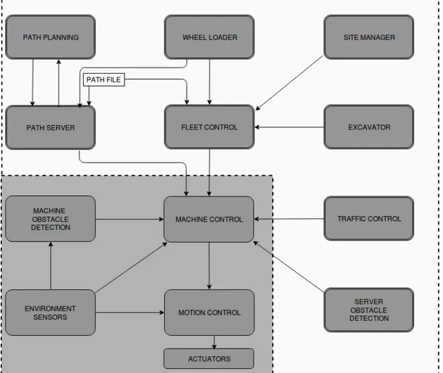
Understanding a ROS source code requires prerequisite knowledge in ROS framework terminologies and structure. Thus, getting familiar with ROS programming is the first task in understanding ROS source code. Since ROS provides inbuilt provisions for hardware, device drivers, libraries, visualizers, message-passing, package management etc. and with basic ROS knowledge, a code walk through was done to understand the HX design implemented in ROS. From the high level design diagram, as given in Figure8, an overview of design architecture is obtained. While creating a high level design diagram, developers have exploited the distributed architecture of HX system in such a way that they are modularized into 1.) Server Module and 2.) Machine Module. In Figure8section with gray background represents machine module and section with white back-ground represents server module. This modularization is made only for better understanding and representation of the design architecture.
In real system, Server Module acts as the centralized control for the fleet operation and co ordina-tion among the vehicles and environment where as Machine Module guides the vehicle to navigate autonomously by perceiving sensor information and reacting through actuators. ROS code ex-ecutes the system by making the components of these modules to communicate and coordinate with each other. An overview of design logic can be described as follows: Fleet Control located at server coordinates the fleet of HX machines while operating. It has two mandatory inputs of current wheel loader position and a global path planner. Fleet Control assigns machine missions and task for individual HX machines in the fleet and track their status. On machine side, sensor data is perceived and is used for computing an obstacle free path and it also coordinates with traffic control component located at server side. HX machines are autonomously navigating vehicles as well as they can be controlled by server side in case of collision possibility.
The basic processing unit of ROS framework is termed as ’Node’, thus by identifying the nodes we figured out the total processing units in the node which are executable and communicating with other nodes. We identified most of the components from design diagram in the ROS code structure. however, few components were not completed implemented at the time of conducting this study. Their functionalities were discussed with the developers for understanding the com-plete picture of HX system design. The nodes are Fleet Control, Machine Control, Traffic
Control, Path Server, Server Obstacle Detection, Motion Control and Perception. All
these nodes are initialized and defined with variables and member functions in order to carry out specific tasks. By going through the member functions of each of these nodes, their functionalities can be derived. However, these functions and other member classes defined in the nodes are loaded with implementation logic and details. We pay less attention to these data and the focus was to look out for relevant functionalities and communication mechanism. As explained in Section2.2, major communication mechanism used for ROS systems are via 1.) Topics and 2. Services The major services used are MapStructure.srv, Path.srv, MachineMissionEta.srv, MachineMission.srv,
LoadComplete.srv, FleetMission.srv and major topics used are for publishing the following
mes-sages: FleetDecisionPoint.msg, FleetStatus.msg, FleetTask.msg, FreePath.msg, machineCmd.msg,
MachineStatus.msg, MotionStatus.msg, ObstacleDetectionCmd.msg, TrafficControlCmd.msg, Mo-tionOdom.msg and so on. This code does not uses any parameter servers for store- retrieve scheme
of communication. At the time of conducting this study, sensor node and perception node was not functionally implemented and they were simulated in Matlab in order to verify other node’s functionalities.
Figure 8: High Level software design architecture
Even though member functions are implementation specific, they are also covered during code walk through process. This gave an insight of certain critical information such as stand alone be-haviour of traffic control from server side. This component manages traffic in the fleet and this is achieved by setting up a critical region and gateways in the path segments, which are highly prone to collisions. These functionalities are achieved by calculating the proximate distance between adjacent machines and estimated time of arrival for the next machine to the segment. void
traffic-Control::gatewayControl(), void trafficControl::proximityCalc(), void trafficControl::setGateways(), bool trafficControl::calcIntersectCircleWL() are certain functions which are critical in managing
3.2 Approach to the Model Development
Once the code walk through is completed on the ROS code, we developed an UML class diagram which represents all the nodes in the source code. Each class included its associated variables, its data types, member functions of the class etc. Also the class diagram included computational and implementation details such as functions calculating position of machine with respect to x, y, z axes etc. Nevertheless, the entire code details are not required to develop its Rebeca model. Hence, in order to extract the relevant details we perform an analysis study with respect to certain criteria as given below:
Include Criteria (IC):
Below are the criteria defined during ROS code analysis for including the extracted entities. IC 1: All the active nodes from ROS source code.
Active nodes are those which shall be in executing state. These nodes has to be sending or receiving data to establish the communication.
IC 2: All the interface connections
All the required inputs for the system as well as communication required for HX -HX or HX-WL connections are identified.
IC 3: Nodes communicating with each other
Every node shall be communicating to an another one or more than one node. The nodes which are communicating with each other shall be identified.
IC 4: Type of data (message)shared across the nodes (as Services or Topics)
ROS communication are of two types- via Services and via Topics. Each of these communication mechanism are modelled differently in Rebeca. Thus these mecha-nisms are distinctly identified.
IC 5: Functional details of member functions
Member function in ROS specifies what needs to be performed by each node. This shall be identified to develop the functionalities in model.
Exclude Criteria (EC):
Following criteria is set so as to exclude certain extracted entities from analyzed data. EC 1: Implementation specific or computational details
Implementation specific details such as distance or position computation or mathe-matical calculation are not extracted from ROS code.
EC 2: Print Functions or Display messages
More specific functions such as print statements or display commands are not logical to be an input for model development, hence they are ignored.
EC 3: Hard coded variables
Variables which are directly assigned to a value to be used for the function imple-mentation cannot be used for model development.
EC 4: ROS specific functions ROS built in functions such as advertise() , callback queue(),
nodeHandle etc. are not extracted.
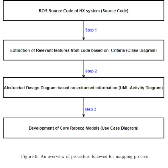
Step 1: The initial phase of the model development process is to extract relevant features
from ROS code. We represent this information using a class diagram, with all extracted data in it. Figure9 shows the entire process, starting with creating a CLASS DIAGRAM with all extracted ROS code details. This unit includes all the required inputs for model development. Information used for this phase are derived from source code and based on include and exclude criteria. This is achieved by doing an entire code walk through and by analyzing each element against the defined criteria. During this process we have also included required inputs for the system, since those are
required for developing the complete model.
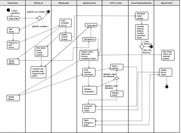
Step 2: The next task is to identify and map the extracted components to match with their
connections so as to establish the communication similar to that of in real system. In this thesis, we have taken an approach to use UML design diagrams to represent the ROS code details as well as to represent the extracted details. Thus, an UML activity diagram is developed as shown in Figure10. This diagram is just one level above the Rebeca model. It represents all the processes and connections relevant to the system. The model developer can use this diagram as a complete reference while developing his model. However, this UML diagrams are not mandatory for Rebeca model development. But it helped to cover all the necessary details of the complex system without missing any data.
Step 3: The third and final step is to develop the Rebeca model based on activity diagram.
However, due to the complexity we have developed two different models to represent the entire system. The first model focused to represent the server design details and communication of server components towards machine; whereas the second model focused to develop machine specific design details. To represent the Rebeca model, UML use case diagram is used in this thesis report. Rebeca models look like a coded Java program and it is a tedious job to explain line by line, hence UML use case diagram serves the purpose of representing an abstract view of Rebeca model.