School of Innovation Design and Engineering
V¨
aster˚
as, Sweden
Thesis for the Degree of Master of Computer Science with
specialization in Embedded Systems 30.0 credits
MOBILE INTERACTION WITH
SAFETY CRITICAL SYSTEMS:
A feasibility study
Erik Jonsson
ejn12027@student.mdh.se
Examiner: Johan ˚
Akerberg
M¨
alardalen University, V¨
aster˚
as, Sweden
Supervisor: Adnan Causevic
M¨
alardalen University, V¨
aster˚
as, Sweden
Company supervisor: Markus Wallmyr,
Maximatecc, Uppsala, Sweden
Abstract
Embedded systems exists everywhere around us and the number of applications seems to be ever growing. They are found in electrical devices from coffee machines to aircrafts. The common denominator is that they are designed for the specific purpose of the application. Some of them are used in safety critical systems where it is crucial that they operate correct and as intended in order to avoid accidents that can harm humans or properties. Meanwhile, general purpose Commercial Off The Shelf (COTS) devices that can be found in the retail store, such as smartphones and tablets, has become a natural part of everyday life in the society. New applications are developed every day that improves everyday living, but numerous are also coupled to specific devices in order to control its functionality. Interaction between embedded systems and the flexible devices do however not come without issues. Security, safety and ethical aspects are some of the issues that should be considered.
In this thesis, a case study was performed to investigate the feasibility of using mobile COTS products in interaction with safety critical systems with respect to functional safety. Six user scenarios were identified for investigation, which could be of interest for industrial applications; The operator presented live machine data, The operator controlling the machine remotely, The service technician using mobile device in maintenance, service technician reading machine logs from the office, the production manager analyzing machine productivity logs from the office and the software manager uploading software. Restrictions in the functional safety standard, IEC 61508, and the characteristics of COTS devices, leads to the conclusion that real time interaction with safety systems is not allowed if the certification is to be preserved. Extracting information used to analyze the system where data is only sent from the machine would be allowed. All scenarios where the machine sends data to the user, and the data is only used as information, are hence allowed if isolation properties are guaranteed. A prototype system was designed and parts of it were implemented to show how sending and logging information can be performed using the company developed communication platform Data Engine.
Table of Contents
1 Introduction 3 1.1 Problem Formulation . . . 3 1.2 Report organization . . . 4 2 Research Method 5 2.1 Contribution . . . 5 3 Use Cases 6 3.1 The Internet Of Things . . . 63.2 User scenarios . . . 7
4 Background 8 4.1 Safety Critical Systems . . . 8
4.1.1 Security . . . 8
4.1.2 Functional safety . . . 9
4.2 Mixed Criticality Systems . . . 14
4.3 Virtualizaton . . . 16 4.4 Distributed Systems . . . 19 4.4.1 Machine nodes . . . 19 4.4.2 Communication . . . 19 4.4.3 Safe Communication . . . 23 4.5 COTS . . . 24 4.5.1 Software . . . 25 4.5.2 Hardware . . . 25 4.6 Data Engine . . . 26 5 Results 27 5.1 Communication . . . 27 5.2 Safety analysis . . . 27 5.2.1 Machines . . . 28 5.2.2 COTS . . . 28 5.2.3 Safety interface . . . 28 5.2.4 Summary . . . 31 5.3 Recommendations . . . 32 5.3.1 User scenarios . . . 32 5.4 System proposal . . . 33 5.5 Prototype System . . . 33 5.5.1 Design . . . 34 5.5.2 Prototype Implementation . . . 35 6 Conclusions 44 7 Future work 46 8 Acknowledgments 47 References 50
1
Introduction
Almost everywhere around us, embedded systems can be found. In coffee machines, amplifiers, in cars and even implanted inside humans, pacemakers can be found to keep up the heart rate. These type of systems utilize one or several computers that are designed and optimized for the specific purpose. In contradiction, general purpose computers such as laptops and stationary computers, are designed to provide high flexibility while being used for many different tasks. Some embedded systems are used in interaction with humans, and if they fail or run out of control it can have catas-trophic effects. In the worst situations, human lives can be lost due to the failure. Such systems are considered safety critical systems. The company maximatecc AB have throughout the years designed embedded systems to control machinery such as seaport container cranes, harvesters and excavators. When controlling machines that posses great powers and currents, it is obvious that failures can cause big damage. To minimize the risks of hazards, it is important to design and test systems in such a way that failures are unlikely to occur. The International Electrotechnical Commission (IEC) have, together with the industry, develop standards that classifies safety re-lated systems. Many machineries, that maximatecc supply control systems to, are certified under IEC 61508 for functional safety at different SIL (Safety Integrity Level) [1]. The standard gives guidelines on how each step in the development process should be performed, which documentation is necessary, which types of tests should be performed and how the product shall be maintained throughout the whole life cycle of the product. New revisions of the EU machine directives is also making it more important to certify products to be able to compete on the market.
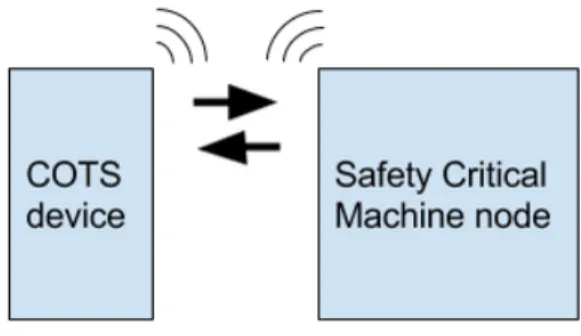
A centrally controlled system has one control unit that controls all parts of the system. However to control machines operating on currents of several amperes the cable costs grows with the size of the machine. Hence, it is many times preferable to have a distributed system where the different parts in the machine communicates via data buses. Input/Output (I/O) controller nodes controls the input from sensors and output to actuators in the system. Accordingly, they usually also contain a communication interface to send and receive parameters from other parts of the system. The last decade there have been an explosion of applications for wireless devices, and Custom Of The Shelf (COTS) mobile devices, such as smartphones and tablets. They offer high functionality with many types of sensors and large computational power. Many applications for these devices have been developed to make everyday life easier. With the wide functionality and usability of such devices the interest of using wireless technology have also attracted the industry and safety critical system suppliers. A wireless interface from a COTS device to the safety critical system would open up many opportunities to new user interfaces. For example it could be possible to read sensor values from the machine and present it on the external device, or even control the system remotely. However, even if existing techniques enables this communication, it is not obvious that it should be done from a safety perspective.
1.1
Problem Formulation
This thesis investigates how and under which circumstances an external, not safety certified, Com-mercial Off the Shelf (COTS) device, like a smartphone or tablet, can interact with a safety critical system such that the safety system still can be certified under the desired SIL in IEC 61508. It also investigates for which type of applications such a communication would be appropriate regarding safety. The problem is defined by a set of user scenarios. In these scenarios two main questions are considered.
1. Is it feasible to use the COTS devices in interaction with the Safety Critical Systems? 2. How and under which circumstances, can an application running on the COTS device
com-municate with the Safety Critical System without violating safety restrictions given by the standard?
1.2
Report organization
In the following section the research method of the thesis is presented followed by introduction of user cases for the study in section3. In section4the functional safety standard IEC 61508, State Of The Art (SOTA) literature study, characteristics of COTS devices and existing company developed software is presented. In section 5 the user scenarios are analyzed from a safety perspective resulting in recommendations and a system proposal. Feasible scenarios in the recommendation are implemented in a prototype design. The work is concluded in section6 and future works are suggested in section7
2
Research Method
The nature of a rather wide problem, as formulated in section1.1requires a well measured method to define boundaries for the research. For example, there are many variants of COTS devices with wireless connectivity enabled and many types of Safety Critical Systems.
Case studies are widely used in social science to study specific situations in human interactions, but also suitable for Software Engineering problems when interacting with technology [2].
An example is in the startup of a large project. Here it is common to investigate if the invention is feasible to avoid unnecessary investments at an early stage. In such a case study, the goal is to find feasible features and demonstrate their concepts.
Runesson and H¨ost [2] gives guidelines on how to conduct a case study in software engineering. They define five major steps in a case study process:
1. Case study design: objectives are defined and the case study is planned.
2. Preparation for data collection: procedures and protocols for data collection are defined. 3. Collecting evidence: execution with data collection on the studied case.
4. Analysis of collected data 5. Reporting
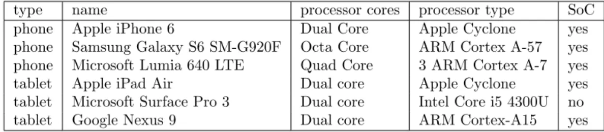
The research method used in this thesis is designed as a technical feasibility study. A set of user scenarios is defined for which the technical feasibility is investigated. The aim is to explore techniques to enable the scenarios and to explain why or why not the scenarios are feasible from the safety perspective. Furthermore, COTS devices are defined with some general features that can be found in most of the smartphones and tablets on the market. Their nature is described in terms of safety features and their wireless connectivity. A few devices from the State-Of-Art will serve as raw models to describe the characteristics.
Subsequently, evidence is collected from SOTA research and standardization restrictions. The approach is hence qualitative, and exploratory in the sense of trying to find techniques to enable the scenarios, and explanatory in the sense of explaining why or why not they are feasible. The collecting of evidence has been made in iterations. When new information was discovered it opened up new traces to follow up, and the research was hence performed in an incremental way.
2.1
Contribution
The contribution resulting from this thesis work is a set of safety recommendations and sugges-tions on appropriate applicasugges-tions for mobile COTS interaction with a Safety Critical System. A prototype is designed and implemented to show how the feasible scenarios can be implemented.
3
Use Cases
Since nodes in a machinery system usually have some communication interface, it could also be possible to connect them to the Internet of Things (IoT). If a node contains a radio transmitter it is also possible to establish a wireless connection to the Internet. If only wired communication is enabled on the node, a connection to IoT could also be realized by wire through another node, serving as a wireless access point or gateway. This section starts with a short presentation of the field of IoT. From that, a set of user scenarios are chosen and described for investigation.
3.1
The Internet Of Things
IoT is the paradigm shift the computer science community have been talking about for more than a decade now. The idea is to equip embedded systems with Internet connectivity devices. Only imagination limits what can be done if systems can communicate over the Internet or other networks. This also comes with potential issues such as usability, security, privacy and safety of the innovation. In surveys like [3] and [4] the big variety of applications thought of in the IoT is presented. Every electrical device from small tags to space crafts fits into the category of things. The only feature that is mandatory on the devices is that they contain some kind of network interface that allows the device to connect to the Internet. There are many ideas on what can be useful as future applications. It spans from Cyber-Physical Systems where the system interacts with the physical environment, to smart sensor networks monitoring and collecting information about the environment. Small RFID chips sending its position on demand that can be attached to single products and machine to machine (m2m) networks where machines communicate to perform shared or related tasks are another possible applications. The ideas also span over all possible domains that humans might act such as smart cities, transport, buildings, energy, living, health and industry. The visions also includes the possibility to utilize cloud services such as analyzing of big data.
Vermessan et al.[5] presents current ideas and technologies for the IoT. They also list appli-cation areas and research challenges. For the scope of this thesis the areas of smart vehicles and manufacturing are the one’s that are closest when considering industrial machines. Business areas like mining, forestry and agriculture are deeply dependent of vehicles in order to be productive.
Application examples described for the industry are: • system monitoring
• repair and maintenance • system control
• augmented reality
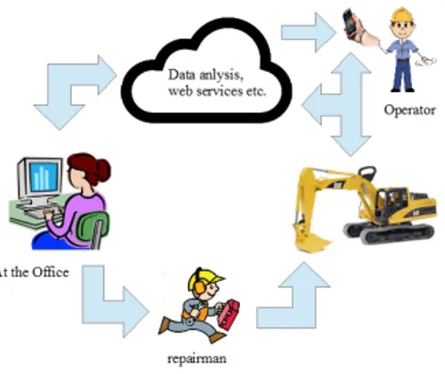
Figure 1: Eco system of several useful applications that can be enabled using wireless communi-cation
In figure 1 several scenarios are depicted that can be enabled for an industry application. Useful applications could be to upload and read diagnostics or logs from the machine. This could for example support the repairman or service technician with information of which spare parts to bring without seeing the machine and alert if a module is getting worn out between regular maintenance. This would be a good tool to reduce costly system downtimes. It could also be possible to alert the operator in runtime that the machine health is getting bad or to upload and install new software or firmware to the machine from the office. If Internet connectivity is unavailable at the working site where the machine operates, it could still be possible to have communication and transmit data in real-time to and from a hand held device when walking around the machine. This could also enable augmented reality applications that could help the user in troubleshooting or performing guided maintenance.
3.2
User scenarios
From discussions with the company supervisor, six possible scenarios where identified where an wireless Human Machine Interface (HMI) could be interesting
1. The Operator presented with live machine data:
The user in this scenario is presented live machine parameters. It investigate how live data, can be presented in real time, to the operator in a COTS device. The user may be anywhere around the machine and still have machine parameters available. It can be useful to know the status of the machine from a remote location in order to make decisions of which actions to take.
2. The Operator remotely controlling the machine:
There can be situations where the operator would like to control the machine remotely from a position beside the machine. For example, a crane controlled using a wireless connection increases the flexibility for the operator and if the line of sight is limited it could be useful to move around beside the machine to get a better view of the situation.
In this scenario parameters shall be set from the COTS device, to an I/O controller in the machine, in order to control its behavior. This could also be done in combination with the first scenario, to display the current parameter values.
3. The Service Technician using the mobile device as help in maintenance:
With smart image recognition and positioning techniques, augmented reality can be realized. This will allow the service technician to look at the machine trough an augmented reality filter. It will enable a connection to the machine that can present guidance in investigating and solving problems without having to read the manual to find the specific error messages. This filter could for example be implemented in Google glasses or a tablet. It would be very helpful in diagnostic applications.
4. The Service Technician reading machine logs from the office:
To help in planning repairs and/or maintenance it would be possible to send machine health parameters over the Internet to the corporation cloud. For example, by utilizing the com-putation power in the cloud, smart pattern recognition comcom-putations can be performed to identify erroneous conditions. This would also enable ordering of spare parts in advance without examining the machine, and hence reduce costly downtimes. With statistics from machine data it could also be possible to analyze and find trends from an entire fleet of machines.
5. The Production Manager:
This scenario is built on the same idea as the previous one and can be used to automatically create daily reports and make them available from the office in the corporation cloud. This would enable opportunities to business process improvements.
6. The Software Manager:
This scenario will investigate the possibility to update firmware and/or software remotely from the office. The machine is set to a specific state used for updates and the software manager uploads and installs the software.
4
Background
In this section Safety Critical Systems and the standard for functional safety (IEC 61508) is pre-sented, which is the object for the considered certification. Furthermore, related works and SOTA research will be presented. It includes Mixed Critical Systems (MCS), virtualization techniques, distributed systems, COTS device characteristics. Lastly a company developed software commu-nication platform is presented. These parts lies as the foundation for the analysis and the system proposal in the following section.
4.1
Safety Critical Systems
Many types of embedded systems exists that are designed for different specific purposes. Some of them are designed to control apparatus that, if they get out of control, could cause big damage that may harm humans or properties. These kind of systems are regarded as safety critical systems and are found for example in the military, machine and medical care industry. Knight[6] describes safety critical systems as ”a system that if it fails can have unacceptable consequences”. The more people that could get harmed from a hazard, the more cautious and careful the system has to be designed, implemented and maintained. For example if the control system of a commercial aircraft with many passengers fails, and the captain cannot steer it anymore, the catastrophe will likely have deadly outcome. Safety put humans in the first place, but it also consider the risk to lose valuable resources or big investments. There are some well known example of Safety Critical System failures.
The Ariane 5 flight 501 space craft self-destructed 1996 at an altitude of 3700 m about 40 seconds after take off due to a software bug when converting a 64 bit floating point to a 16 bit integer. No humans where harmed but huge amounts of resources where lost [7]. Therac 25 used in the mid 1980:s is an example where a software problem have killed people. The radiation therapy machine emitted radiation doses several levels of magnitudes higher than intended because of programming errors. Six persons got severe wounds and four of them died [8].
In US military the Patriot missile defense system failed to demolish incoming SCUD missiles from the Iraqi army during the Gulf war. The failure was due to inaccurate precision in the arithmetic calculations in the system. This led to a loss of 28 soldiers and wounding around 100 civilians [9].
Aftermath from these and other accidents have increased the awareness of safety and the de-mands for risk reduction when new systems are developed. From these discussions, safety standards have evolved.
It can be argued that risks shall always be minimized as much as possible. The loss of a life is invaluable. Doing that would however postpone release dates and hence also technological advantages such as environmental and energy savings, and at the end, there would still be a small risk that something fails. Hence, it is more common to balance the risks and the costs and reduce the risk to a tolerable level.
It is important to realize that safety and reliability are not the same thing. Safety system always puts the safety of humans in the first position. A highly reliable system could be a gun that always fires when the trigger is pulled, and such a system could obviously harm somebody if it’s aimed in the wrong direction. What is aimed for is a reliable safety system.
When developing a product that is meant for safety purposes it is usually a good idea to aim to certify it, not least considering laws regulating it in some countries. In some countries it would also be possible to sue a company delivering products not meeting safety requirements when an accident have occurred.
4.1.1 Security
Every embedded system that have the equipment to connect to external sources is under potential security risks. Security of data aims to protect data from unauthorized access and manipulation.
Hackers have over the years been able to intrude in systems such as banking and National Aero-nautics and Space Administration (NASA) that should be considered having high awareness of security. Recently it has also been shown that modern cars can be hacked and controlled remotely [10][11] and last year (2014) we could read the news that somebody had hacked into a nuclear plant in South Korea [12] and stolen information about the system and the facilities.
In the computer science security community it is common to discuss confidentiality, integrity and availability of systems. Confidentiality targets that unauthorized users should not be able to spy and read data from the system, and integrity that changes to data should not be possible. A typical threat against availability is a Denial Of Service (DoS) attacks when the system is disrupted or overflooded so that authorized request to the system becomes slow or even totally unavailable. Many books and articles such as [13] [14] covers techniques to handle these issues. Security should of course be considered when designing Safety Critical Systems, but it will not be the main focus in this report.
4.1.2 Functional safety
Functional safety considers the design and implementation of safety related functionality, mainly meaning functions of the system that are interacting with humans and environments. This sec-tion presents a brief summary of IEC 61508 and a selecsec-tion of commonly used techniques. It also presents the significance of a rigorous and careful development process.
Overview of IEC 61508
IEC have developed standards which guides engineers in development of new safety related prod-ucts. IEC 61508 [1] is the standard for functional safety. In IEC 61508 -1 the aim of the standard is described:
It ”sets out a generic approach for all safety lifecycle activities for systems comprised of electrical and/or electronic and/or programmable electronic (E/E/PE) elements that are used to perform safety functions.”
In IEC 61508 -4, safety is defined as: ”the freedom from unacceptable risks” and functional safety as:
”part of the safety relating to the EUC and the EUC control system that depends on the correct functioning of the E/E/PE safety-related systems and other risk reduction measures” where EUC is short for Equipment Under Control.
IEC 61508 consists of 7 parts.
• Part 1 describes the general requirements and the development life cycle activities. • Part 2 focus on the realization phase of the system, mainly referring to hardware. • Part 3 part focus on the realization of the software.
• Part 4 gives abbreviations and definitions of terms.
• Part 5 gives examples of methods to perform risk and hazard analysis and to determine the SIL.
• Part 6 gives guidelines for the application of parts 2 and 3. • Part 7 presents an overview of safety techniques and measures.
An independent authorized person, department or organization will examine if the product con-forms to the standard and if it does, it will be certified. For high SILs it has to be an independent organization that examines the system and for low SILs it can be a single person. An important
part of the process when developing a safety related product is accordingly to collect evidence for conformance to the standard.
Development process and techniques
The first part of the standard, describing the general requirements, presents four important as-pects that should be covered. Documentation, management of functional safety, overall life cycle requirements and functional safety assessment.
The objectives of the documentation is to provide and specify all necessary information in order to enable that all phases in the life cycle can be carried out effectively. New additional documentation will be produced and added in each phase. The documentation requires that sufficient information shall be provided for all phases, that it is well structured, and that it shall be reviewed to ensure that it is accurate, concise, easy to understand for those who are to make use of it and suit the purpose for its intention.
In the management of functional safety, the objectives are to specify activities and responsi-bilities of who in the project team that is responsible for which phase, or safety related E/E/EP systems, and who will carry out which specific activity. One person can, for example, be responsible for the hardware safety and another one for the overall design. Except from assigning responsibil-ities, the requirements includes making sure that persons assigned to the activities have the right competence, and that all persons involved will get the right training to perform assigned tasks. This also means that experienced persons have to refresh and update their current knowledge of safety. It also provide means to assure that the communication channels and procedures in the project are clear and the interfaces between different phases, where different persons are respon-sible, is planned for and handed over in a proper way. Procedures should also be developed to ensure prompt follow-up and resolution to problems raised, with an extra attention to hazardous events. This also includes all related analysis and documentation matters.
The objective of the functional safety assessment is to specify necessary activities in order to be able to investigate and judge if the E/E/EP safety related systems will comply to the standard. The overall life cycle requirement presents a framework that defines 16 phases for the product life cycle from concept to decommissioning. Each step has its objectives and requirement to fulfill. The precess flow shown in figure2presents each phase and in which order they shall be carried out. Each phase has its inputs and expected outputs. The realization phase (10) is described explicitly for hardware and software respectively. Generic objectives for each phase can be found in table 1 in IEC 61508 -1.
Figure 2: The Overall Safety process described in IEC 61508 -1 [1]
Many of the phases can be found in any project process model such as the V-model. Scope definition, allocating requirements and specification, realization and validation are all such exam-ples. Just like in any project there may also be reasons that forces the project to loop back to an earlier phase to complement that phase and all its subsequent phases. Examples are if the product does not pass the validation tests or if a new hazardous event is discovered. The similarity of the processes makes it relatively easy to include safety in a project, but also increases the requirements of how the phases shall be performed. The phase that sets the character of the safety process is the hazard and risk analysis which all other subsequent phases will depend on. In this phase the objective is to determine hazards and hazardous events in the scope relating to the EUC. The analysis will be used in phase 4 to specify the overall safety requirements which in turn is used to determine SIL when the overall safety requirements are allocated in phase 5. There are 4 SILs in IEC 61508, 1-4, where 4 is the highest level with the most stringent requirements.
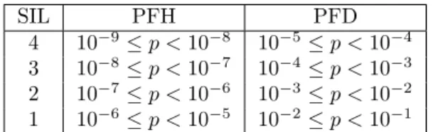
To determine the SIL, measurements of the risks and the probability that they occur are performed. Low demand probabilities of failure for safety functions that are rarely used, for example airbags, is measured in Probability of Failure on Demand (PFD). Functions that are often or continuously used are measured in Probability of Failure per Hour (PFH). The SIL and corresponding probabilities are presented in table1.
SIL PFH PFD 4 10−9≤ p < 10−8 10−5 ≤ p < 10−4
3 10−8≤ p < 10−7 10−4 ≤ p < 10−3
2 10−7≤ p < 10−6 10−3 ≤ p < 10−2
1 10−6≤ p < 10−5 10−2 ≤ p < 10−1
Table 1: Probabilities p for determination of SIL targets
IEC 61508 -5 presents a set of techniques to perform the risk and hazard analysis and for determining SIL targets. The objective is to identify the hazards and hazardous events to enable collection of evidence that such events will fit to the aimed SIL. This can be carried out by quantitative or qualitative methods or in combination.
One technique to perform risk analysis is to construct a Fault Tree and perform a Fault Tree Analysis (FTA). The tree is drawn from the hazardous event and backwards to track what can cause it. An example of a hazardous event can be that the brakes fails. In the first step, all causes that makes this happen are considered. In the next step the reasons ending up in these situations/states are considered, and so on, in a sequence of steps. In the last step, the tree will show one or more things that when they fail that potentially can cause the hazard directly or in chain reactions leading to it. The final tree will look like a system of logical gates with a number of inputs followed by AND and OR gates. By using this analysis it will be possible to make quantitative measures in the design phase to produce a reliable system within the tolerance of the intended SIL. The human factor should be considered in the analysis, but to quantify and determine frequencies of human behavior is hard and is not a requirement in the standard.
SIL targets can also be established using risk analysis graphs where qualitative judgments are involved. Functions and failures are categorized from the severity of the failure like in the risk classification approach shown in Table2. It involves assessments of consequences and frequencies where a negligible risk could be that the background lights on the instrument panel is malfunc-tioning in the driver cabin while a catastrophic failure could be that it will become impossible to use the brakes.
FREQUENCY CONSEQUENCE
Catastrophic Critical Marginal Negligible
Frequent 1 1 1 2 Probable 1 1 2 3 Occasional 1 2 3 3 Remote 2 3 3 4 Improbable 3 3 4 4 Incredible 4 4 4 4
Table 2: Example of Risk Classification approach
Intolerable region is covered by 1, tolerable region of 2 and 3, and the acceptable region of 4. For region 2 and 3 it is good practice to reduce the risk to a level As Low As Reasonable Practicable (ALARP). The method considers, as the name implies, that the tolerable risks should be reduced as much as possible until the time and cost expenses would be unproportional to the project.
It should be noticed that the specification will be a week point in the process. If it is missing a requirement or contain ambiguity it will be a single point of failure which will be propagated into the design and implementation phases. This is accordingly a very important part of the process to make correct and complete. Therefore formal methods are used when high SILs are considered. Formal methods specifies notations that shall be used in the specification of the system requirement. With specific notations these methods makes it possible to prove certain properties by logic reasoning. For example, it can be proven that the property: it should always be possible to start the failsafe procedure, holds. The property will in this case be true for every state of the machine.
Quantitative evidence rely on things that can be measured and calculated by statistics. These techniques heavily refers to physical issues in the hardware where components or modules have documented failure modes and probability for them to occur. Random hardware failures can be
caused for example by worn out components or extreme values in the physical environment. As evidence from the development of the hardware it is common to provide a Failure Modes Effect Diagnostic Analysis (FMEDA) report. FMEDA is a quantitative method used to prove that the hardware failure probability is at least as low as the SIL requirement. For example it is possible to calculate Bit Error Rate (BER) depending on the distance between two wires, or to measure the failure rates of single components such a capacitor and resistors. These rates and the modes of failures are usually provided by the manufacturer. The calculations are performed in Failure In Time (FIT) units, where 1 FIT is equal to the Probability of Failure per Hour (PFH) of 10−9. For example a system with SIL 2 should have a FIT value between 100 and 1000 in analogy with Table
1. When interconnecting two modules of the system the FITs are added and the total FIT will now be the sum of the two modules. By adding redundant modules the FIT value will decrease. In redundancy M out of N (MooN) components is used where for example 3oo5 means that 3 out of 5 available units must work correctly for the device not to go dangerous.
In hardware it is also common to use read-backs of the output. This technique is employed to make sure that what is sent is the same thing as intended. This is achieved by looping back the output signal and compare it to the sent signals. If the signals differ too much a fail safe procedure shall be triggered.
Systematic failures such as flaws in the specification or bugs in the software however are not easy to calculate by statistics. Even if one would try, it would be hard to find the distribution of the errors. Evidence for reduction of this kind of failures are hence provided by using qualitative methods.
Hazard and Operability Analysis (HAZOP) is a structural method to examine documentation and to analyze the system design together with other engineers in the project team through a series of meetings to ensure its correctness. The aim is to determine safety hazards in the proposed or existing system, their possible causes and their consequences, and to recommend techniques to minimize the risk of their occurrence. The group leader shall encourage the participants to creatively expose all potential hazards. HAZOP can be performed at any phases of the development cycle and is recommended to be applied at an early stage to avoid mishaps later on.
One technique to implement fault tolerance is to use redundant modules, meaning that there are several instances of the same module in the system. It can for example be several sensors of the same kind at almost the same spot. A voting system compares the sensor values and validate which values to use in the system. If something is wrong the failsafe procedure shall be started. If a systematic fault in a module exists, all the redundant modules can be expected to make the same mistakes. Therefore, it is also common to implement diversity in systems. Given some input and expected output there are many ways to produce the output. With diversity, heterogeneous systems are considered. The developers find different ways of implementing the module. All solutions should of course fulfill the specification. For software development this approach is called N-version programming [15]. A voting system is used here as well. One voter alone would present a single point of failure, but it is also possible to have several voters for the same inputs to enhance the safety. With several actuators the safety can be enhanced even further. This increases the fault tolerance in the system. Another strength with N-versions, regarding software development, is that it is possible to use different programming languages or compilers in the development to increase the diversity even more.
Another often used technique for software development is defensive programming where it is checked in the code that incoming values are within acceptable ranges. Depending on the application, this can for example be min and max boundaries from the current value or simply extremes.
Standards also give restrictions and recommendations on methods to use when building the software. For example it is for higher SILs required that dynamic memory should not be used since it is easy to make programming mistakes with for example reading or writing outside an array. It may also be complex to keep track of where data are stored in memory and how much that is allocated at a specific point. Running out of memory during execution can cause unexpected behavior. Many times, the number of commands used in a programming language is reduced to a subset of commands to reduce the options and simplify the analysis.
The standard also take in aspect related good practices in code structure, such as well com-mented and readable code. The compiler shall also be chosen with respect to proven functionality
and should have been tested in use.
Watchdog timers can be used to monitor functionality. It is a clock ticking downwards. If the timer reach zero it will start the fail safe procedure. A properly working system will reset the timer periodically to a given value. Several other types of monitoring techniques also exist. For example one module can monitor that another module is working properly and making correct computations.
It is also the responsibility of a safety system to fail in a safe way if a hazardous event is detected, often with the meaning that all actuators shall be disabled without any delays.
In the project process, planning for maintenance, validation, installation and commissioning are performed in parallel with the implementation phase. The final phase in the process is decom-missioning and with that the whole life cycle of the product have been covered.
An important aspect to keep in mind when developing a safety related product is that evidence of conformance to the standard is necessary for all parts of the system, both hardware and software if it should pass the certification. There should also be evidence showing that the process was carried out compliant to the standard and that the documentation is sufficient.
Another thing to notice is that since the safety functions have to be validated and verified extra rigorous. Hence, it is better to keep them as simple as possible. The more complex they grow the harder will it be to verify their correctness.
4.2
Mixed Criticality Systems
A Safety Critical System can hold functionality of different critically levels with both highly critical tasks, less critical tasks and regular tasks. Such systems are called a Mixed Critical Systems (MCS). One example can be a pacemaker, which have the critical task of giving electrical pulses to keep the contraction pace of the heart and other tasks such as sending heart rate data and/or battery status to an external device. Another example is in a commercial aircraft, where we have both the steering and video entertainment systems in the aircraft. To make a system safe, safety have to be considered for the whole system including the entertainment application. It would of course be costly and a waste to certify the entertainment system for safety. Standards do however allow mixed criticality levels within the same system if they can be isolated in such a way that the safety of the highly critical steering system cannot be affected by the entertainment system. To guarantee this, the functions have to be isolated and separated both in temporal and spatial domains. The temporal domain refers to the separation in time and spatial to memory and resource handling. It includes both the user memory accessed during runtime of the application, and the kernel memory handling. This can, for example, be done by statically allocating and dedicating memory for different functions.
Burnes and Davis [16] presents a review of the research from 2007 to 2014 and present chal-lenges for further research regarding MCS. Much attention has been drawn to find good scheduling algorithms to separate tasks in temporal domain on single processors, such as Fixed Priority Scheduling (FPS) and Earliest Deadline First (EDF). There are plenty of work done on how to effectively schedule jobs to ensure that mixed criticality functions do not interfere with each other [17][18][19]. Embedded systems with several processors and modules on the same chip consumes less energy than solutions using single processor and multiple chips. To analyze these systems, sometimes including Networks On a Chip (NoC), presents challenges to researchers in order to isolate functions of different criticality level.
Pellizzoni et al. [20] presents a design methodology for Systems on Chip (SoC) to guarantee temporal and spatial isolation in a MCS. A formal method is used to together with a set of certificates that describes the intended applications behavior. The tools presented in the paper that applies the methods, automatically generate hardware wrappers that enforce the behavior defined by the certificates. In particular, run-time monitoring is employed to formally check all data communication in the system is temporally isolated. The tools are demonstrated and tested in a case study of a pacemaker system, where mixed critical tasks of diagnostics, logging and heart contraction runs in the same system. A RF transmitter enables wireless communication and setting of certain parameters without intruding the highly critical tasks.
If jobs or functions of different criticality are to communicate, we face a tougher challenge. The functions are now interacting and the high integrity level for the safety critical functions
Figure 3: Totel’s integrity model for communication between different SIL in a MCS [21]
should be preserved. One way to achieve this, as mentioned, is the costly way to design all modules in the system at the highest intended integrity level. Totel et al. [21] however, presents an integrity model that enables communication between different levels of integrity. The only concern for downstream communication from a higher SIL to a lower is to make sure that there is no backward leakage. This is defined as the diod property. Totel’s model shown in figure 3
also suggests a special channel through which data from a lower SIL can be upgraded and used at a higher level. To ensure safety, all information going upstreams have to be validated to the intended level. This channel is secured by a Trusted Computing Base (TCB), that offers a specific entry point for the upstream communication and the diod properties. The TCB consists of a micro kernel used to schedule messages and an integrity kernel that ensures that the information moves in the correct direction of the TCB. Before the data is upgraded to the new level it also have to be validated by a level specific validation object (VO). These validations are performed using common safety techniques. A specific TCB have to be implemented for each SIL to SIL communication. The model also presents multi level objects that could be implemented for the highest intended SIL but operate at any level. When it is used on a lower level though there is no way to upgrade such an object back to a higher level again. Such an object would require that the highly critical task is executed before tasks on lower levels and would hence not enable upwards communication. Laarouchi et al. [22][21] evolves Totel’s model to be useful in distributed systems and purposes use of virtualization in avionic systems. Furthermore, they use Totel’s model to enable the communication to the avionic system in the Airbus from a COTS laptop, and present how the techniques can be used for maintenance scenarios [23]. In addition the take-off procedures case for avionic systems is considered in [24] that also proposes the use of proxy TCBs where one TCB is implemented between each consecutive SIL instead of one for each SIL to SIL. In this way a communication from level 1 to 4 have to pass through 3 TCBs and validated by a validation object at each level before it can be used.
Wasicek et al [25], inspired by the work of Laarouchi et al. also evolves Totel’s model to work on a MultiProcessor System on Chip (MPSoC) architecture in the ACROSS system for vehicles. The proposed design uses virtualization and is implemented on a time triggered architecture. Furthermore they demonstrate the design in a car system where an omnimeter sensor is used both for counting traveled miles and the braking system utilizes. This seems to be a promising approach but Wasicek et al. concludes that more research need to be done in order certify this kind of systems.
From papers citing the model proposed by Totel et al only a few papers focuses on connecting COTS to critical systems and it seems to be limited to one research group. A weakness besides this is that the hardware of COTS is never considered. From standards such as IEC 61508, that is an important part of certifying a product for safety.
4.3
Virtualizaton
As several papers in section4.2have stated virtualization would offer isolation properties that is a requirement for MCS. This section presents these techniques with attention to how they could be utilized in a MCS with respect to the goal of communicating with a COTS device.
The term virtualization refers to a software abstraction layer where an OS or application running above it is unaware of it. The virtualization mimics the real environment that the program or OS is adapted to. Hence, for example the OS, can operate in the same way as it should have done if it ran directly on the hardware. This virtualized environment is usually called a Virtual Machine (VM).
The first virtualization technique was developed by IBM back in 1964 [26] and has been used in servers ever since. The increasing numbers of transistors on chip and cheaper hardware however made the interest of virtualization fade during the following decades. With the increased usage of the Internet and the need for storage and analysis of big data in servers, new virtualization implementations came in the late 1990:s and during the 2000:s. The Xen and Azure hypervisors gave virtualization a new push forward and the techniques are today widely used in data centers. During the last decade the power of virtualization has been exploited in the domain of cloud services. Big companies such as Amazon and Microsoft are nowadays offering Infrastructure as a Service (IaaS), Platform as a Service (PaaS) and Software as as Service (SaaS). The IaaS provides an infrastructure and hardware resources for virtualized OSes and servers. This infrastructure makes it possible for a company to rent hardware on a data center instead of buying and keeping own in the house. PaaS provides a platform and all needed to care about is to develop the application meant to run on that platform. For example, a web server platform can be rent, with all the support (linux, apache, mysql, php, etc.) needed to run a website. All the tenant have to care about is the coding. SaaS separates the application software from the platform and can give access to different editors for example through the web browser. This for example, enables the user to edit documents or to send e-mails without installing any editor or mail client on the own system.
The Virtual Machine Monitor (VMM) also called the hypervisor is a specially designed OS that handles and manages resources among the Virtual Machines (VM) running on it. An OS that runs in a VM is called the guest OS and the underlying hypervisor OS i called the host. There are mainly two types of hypervisors today.
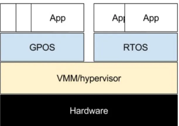
Type 1, also called ”bare metal”, runs directly on the hardware and manages the real hardware resources among the guests running on it. This architecture makes it possible to move a whole guest OS from one piece of hardware to another. Hence a server crash in a data center do not have to make the services unavailable for a very long time since the OS easily can be migrated to another machine. Running several different guests on the same piece of hardware also enables better resource utilization. In data centers, several lightly loaded server systems can for example run on the same hardware and still deliver its services with adequate quality. If the resources becomes a limit for the performance at some point one of the guest OS can be migrated to another less loaded piece of hardware and in that way balance the total load among the hardware in the data center. It is also possible to run different types of OS such as (General Purpose OS) GPOS and (Real Time OS) RTOS on the same machine as shown in Figure 4. The GPOS could for example be used for regular applications, a RTOS for controlling hard real time tasks.
Figure 4: Type 1, bare metal, hypervisor design
Type 2 hypervisor is called ”hosted”. As illustrated in Figure 5 it runs like an application in another OS. This makes it possible for a programmer or designer to run and test applications in different environments in a convenient way on the same machine saving a lot of time and space.
Figure 5: Hosted, type 2 hypervisor design
Hypervisors are furthermore divided into two main types of virtualization.
In native or full virtualization, a binary copy of a guest OS can be installed directly in the VM on the hypervisor without any modifications. The hypervisor is responsible for trapping and handling all requests from the guests. It is rather easy to port an OS to this architecture but it has been shown that extra overhead especially in the memory handling has bad impact on the performance. The issues with the virtual memory handling in page tables and system calls where addressed by Barham et al. [27] which introduced paravirtualization in the Xen hypervisor. With as small as possible modifications to a number of OSes they managed to reduce these overhead costs of the hypervisor.
In paravirtualization the guest OS is modified to replace all privileged instructions with explicit calls to the hypervisor API. These calls are called hypercalls. Paravirtualization also allows to replace multiple privileged instructions with a single hypercall, reducing the number of context switches between privileged and unprivileged modes. These rather simple changes makes the paravirtualized versions perform closer to an OS deployed directly on the hardware and is the most widely used technique today.
Reinhard and Morgan [28] demonstrates that a hypervisor can be built to run on a rather simple processor and run multiple paravirtualized VMs on it and states that the bare metal hypervisor could be useful for running applications separated on the same ECU especially where isolation is
important. Landau et al. [29], have also shown that it is possible to implement hypervisors for multi core processors and even dedicating CPUs to specific VMs.
Gudeth et al. [30] argues that bare metal hypervisors are to be preferred for security appli-cations. All hypervisors found during this background research, that are designed for security purposes, are also of this type. The argument that the extra layer in a hosted solution would be a security risk can directly be transfered to a safety related application. The extra software and complexity would also make it harder to analyze. For security and safety applications the Trusted Computing Base (TCB) of the kernel should be kept small. The type 1 hypervisor seems to be preferable over type 2 for our purpose.
Hypervisors are however not the only way to achieve virtualization. Microkernels such as L4 [31] has been demonstrated to support paravirtualized OS. While hypervisors are developed to run several VMs simultaneously on the same platform the microkernels aim to keep the kernel as small and simple as possible, by minimizing the amount of privileged code and moving things that do not necessary need to be in the kernel out of it such as device drivers, file systems and I/O. The TCB is kept small but microkernels seems to suffer from a high load of context switches and calls to the kernel. Microvisor is what OKL4 [31] call their hypervisor of which they have tried to reduce the hypervisor kernel to a minimum. More recent microkernels have improved the performance to acceptable levels.
In distributed systems like in cars with many ECUs, keeping the Bill Of Material (BOM) down is a selling argument for virtualization techniques. By virtualizing, it is possible to physically remove ECUs close to each other and use one instead with virtual machines running on it and for example, allowing MCS like ABS braking system and the radio receiver at the same unit.
The speed, size and energy consumption have usually been optimized for the purpose of the application in embedded systems. Hence, efficiency and utilization problems that motivates virtu-alization in data center are usually not an issue for mobile devices. Some properties do however make virtualization interesting for mobile applications as well.
Many applications have been developed and used in the highly flexible OSes provided with the mobile devices. When viruses, trojans and other malware have been intruding more frequently in these softwares, the motivation for securing these devices has increased. The isolation properties of virtualization drew the attention to mobile vendors.
Both ARM and OK labs published white-papers [32][33] a few years ago with software tech-niques that potentially may make smart-phones and tablets useful for security or safety applica-tions. Both present virtualization techniques to isolate software in temporal and spatial domains. In 2009 Motorola released the first smartphone, Evoke QA4, with support for virtualization. Many others have followed and in recent years several hypervisors have reached the market sup-porting ARM and Intel processors widely used in mobile devices.
One of the applications that have been a driving force in the development of virtualization for mobile platforms comes from the idea: Bring Your Own Device (BOYD) to work. The idea origins from the fact that many employees have to carry two smartphones in their pockets. One private and one for the corporation. Companies want to keep their data secure and hence private phones, with a big diversity of softwares, are not trustworthy. However, by running an isolated VM on the smartphone it is possible to design and implement a secure interface to the corporation network. Some high tech companies are already using this technique and reducing the Bill Of Material (BOM) since they don’t need to supply all employees with company phones anymore. BYOD could also enable employees to work remotely on devices that they are familiar with instead of having to adapt and learn a new system. These things and the flexibility to work anywhere could also increase the productivity. VMWare among others, have also demonstrated that an user friendly implementation makes it possible to switch from one VM to another almost like switching desktop screen [34]. Cells [35] is another solutions for running several virtualized phones on the same platform that enables BYOD.
Just like these kind of security applications it could be possible to use virtualization and VMs to isolate tasks for safety purposes from others. Prioritized RTOS have been shown to meet deadlines and ensuring real time behavior, and vendors like Wind River, Green Hill and PikeOS offer safety certified hypervisors for ARM platforms that often are found in mobile products. These hypervisors have been tested for applications in avionics and vehicle industries. Some other virtualization giants such as KVM, Xen, OKL4, VMWare and Red Bend are also developing mobile hypervisors [36].
Virtualization techniques may be used both on the machine side and/or on the mobile COTS device side to offer the possibility to implement safe software platforms beside regular applications on the same hardware.
4.4
Distributed Systems
Many systems are built by several subsystems or devices called nodes in a distributed system. To make the whole system work properly the nodes need to communicate and exchange data in order to perform its job. Machinery systems are often distributed system where nodes are placed closed to its operational functionality in order make installation simpler and to save power cable lengths. A combine harvester harvesting grain crops, for example, have nodes for controlling the cutting mechanisms, the threshing drum, straw walker and the straw chopper, distributed over the machine.
This section presents some typical machine nodes, how communication between nodes works and the meaning of safe communication. In this thesis, wireless communication between mobile COTS devices and machinery systems is considered. Therefore some extra attention is spent on such protocols, and less on internal machine communication.
4.4.1 Machine nodes
An I/O controller is a device that controls inputs from sensors and outputs to actuators. In machine control systems it typically contain a DC/DC unit that transforms power input into all necessary voltage and current levels. It typically also have communication peripherals such as CAN and/or Ethernet connections. Hence the I/O controller can communicate with other parts in the system to give or receive instructions. Analog inputs from sensors are usually converted to digital using an Analog to Digital Converter (ADC). Motors and hydraulics are typically controlled by coils and electromagnetism using Pulse Width Modulation (PWM) signals. For example in a hydraulic cylinder, a PWM signal is modeled to control the valve that regulates the pressure and hence the force that the machine needs to perform its task. Other typical input and output are digital on/off signals. The micro-controller is the brain in the I/O controller. It is responsible for performing calculations and making decisions according to its programmed instructions.
Machine functional safety is not in the scope when developing a new I/O controller. It cannot be predicted how throttles, motors or valves will be connected or which ports that will be used. It can only be ensured that the product developed performs it intended actions properly and safe and holds features to perform or trigger safety functionality. It can for example be verified that the PWM-signal emitted is correct, and if its not, handle the error in a safe way.
A safety I/O node is usually delivered with certified hardware, firmware and an Application Programmers Interface (API). Software such as a certified RTOS can also be provided.
Another important node often found in distributed machine systems are the job computer, which works as a central node to coordinate the I/O nodes.
Other typical nodes found in machines are I/O nodes connected to user interfaces such as joysticks and displays.
4.4.2 Communication
To enable communication there have to be a sender and a receiver. A simple example is Alice and Bob talking to each other. When Alice says something, sound waves are sent/transmitted trough the air and received by the receptors in Bobs ears. Bob then processes the information in his brain and responds. Typical problems would be if Bob do not listen, occupied with something else, or if Alice speaks a language Bob doesn’t understand. To enable electronics to communicate, protocols have been defined to make the sender and receiver understand each other. The Open Systems Interconnection (OSI) reference model shown in figure6, defines 7 layers of protocols that can is used by nodes to communicate. Each layer is responsible for different parts in the communication, provides services for the layer above and presents data to the layer below in the predefined form. Tannenbaum [37] presents a comprehensive description of computer networks including the OSI model depicted in figure6.
Figure 6: The seven layers of the OSI model
The first layer handles the physical aspects of the communication such as radio transmitters, connectors and cables. The protocol in this layer defines voltages, frequencies and electrical pulses. For wireless communication it is considered how the signal is modulated on the carrier wave. This can be done by defining the meaning of different amplitudes, frequencies or phase shifts. Another physical aspect to consider for communication is the range. Higher frequency gives shorter ranges than lower due to attenuation. Higher frequencies however deliver higher data rates.
The second layer is the data link layer. The main task of the layer is to produce a data frames in the size defined by its protocol and present them to layer one. The layer concerns the link between two nodes and that messages are transmitted. An important part of this is the Medium Access Control (MAC) layer, which defines how the nodes may utilize the medium. The MAC layer is divided in two main variants of protocols: contention-free and contention-based. Contention-free protocols are designed to avoid that nodes within the network interfere each other. This can for example be done by dedicating time slots or frequencies for different nodes. If some node do not use its slots this will be a waste. An example of such a protocol is (Time Division Multiple Access) TDMA. Contention-based protocols calculate on having contention in the network, but nodes do on the other hand not have to wait for its slot before transmitting. The Carrier Sense Multiple Access (CSMA) widely used in computer network is such an example. Problems can occur if two or more nodes transmits at the same time. There exists several techniques to handle this. The two most widely employed ones are the Collision Detection(CD) and the Collision Avoidance(CA). These protocols uses small Request To Send (RTS), Clear To Send (CTS) and Acknowledgment (ACK) packages to inform other nodes of its transmission state. If a node sends a RTS package the surrounding nodes can hold there own packages until the transmission is finished. Many more MAC-protocols exists.
The third layer is the network layer. It controls how the package shall be routed from source to destination in a network. Routing protocols controls where a received messaged shall be forwarded to reach its destination. There are several known protocols here as well. A simple example is the flooding algorithms where packets are sent on to all other nodes expect from where it comes from. Nodes keep records of which packets that they have already flooded and do hence only flood once. Other protocols utilize routing tables to direct the communication to specific nodes. This usually decreases the number of transmission and hence saves energy. The Internet Protocol (IP) provides uses IP-addresses to in order to route packets. Subnetting is a course on its own regarding this.
The fourth layer is the transport layer. The main task of this layer is to provide a reliable and cost-effective data transport from source to destination. The layer is a glue between the underlying layers and the upper ones in the TCP/IP model, making it possible for the programmer to implement applications with less care on how packets are routed and transmitted from source to destination, usually referred to as socket programming. The transport layer provides that service. The two main Internet protocols are the connectionless User Datagram Protocol (UDP) and the connection-oriented Transport Control Protocol (TCP). UDP is connectionless meaning that it do not care of establishing a connection to the receiver before sending, which is the case for TCP. UDP is more used for sending single datagrams of data while TCP is used to stream much data.
The fifth layer is the session layer. It controls communication sessions between computers, and manages the connection between local and remote applications.
The sixth layer is the presentation layer. Unlike lower layers moving bits around, this layer is concerned with syntax and semantics. In order to make it possible for different applications on different platforms to communicate this layer handles the presentation of the data. It maps it in an for the application understandable way.
The seventh layer in the model is the application layer. It is the layer closest to the user. This is where data is presented to the user and where he can interact with the system. A typical protocol in this layer is the Hyper Text Transfer Protocol (HTTP), which is widely used in web browsers. Other well known protocols are File Transfer Protocol (FTP), Simple Mail Transfer Protocol (SMTP), and Secure Socket Layer (SSL).
A network application employs the OSI stack to enable its features. When a message are to be transmitted it works downwards in the stack attaching headers for the protocols on the different layers. The message is then sent over the physical channel. The receiver reads the headers in each layer in reversed order to direct the message to the receiving application.
Not all nodes involved in the communication reads all headers. For example a router working in the network layer only reads and removes the first three layers. With that information it decides where to route the packet and works it’s way down through the underlaying layers attaching new headers and forward it to the next node. A data switch, working on the data link layer, only consider the two lowest layers.
Which protocols to use for a specific application is a design issue and depends on what properties that are important. Aspects that could be of interest are for example reliability, scalability, latency and energy consumption.
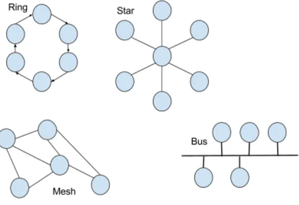
Moreover communication networks can be formed in different topologies as depicted in figure
7, which describes how the nodes are connected to each other.
Figure 7: Network topologies
They can for example be connected in a ring where all nodes have two neighbors. One to the left and one to the right. The line topology is almost the same, but it have end nodes which only have one neighbor. The star topology have one node in the middle to which all other need to send to in order to communicate to the other nodes. Another topology is the tree where nodes have one parent and child nodes. Especially in wireless network the topology is not fixed since nodes are mobile. In such applications it is common to work with Ad-Hoc networks to which new nodes can connect. When nodes can be connected to each other in different ways it is called a mesh. In a fully connected topology all nodes will be connected to every other node in the network.
In vehicles and machinery systems the communication is usually performed on data buses. A bus is a network topology where all nodes communicate over the same channel. The Controller Area Network (CAN), widely used in the automotive industry, is an example of a protocol de-fined for the two lowest layers in the OSI stack operating on the bus topology. CAN is designed for time critical systems, where a deterministic behavior is crucial. In CAN all nodes have an unique id which also presents the priority of the messages from the node. A message from a highly prioritized node will always be sent before a lower one if the nodes try to send at the same time. This makes it possible to calculate worst case times for messages of different priority on the bus. Other protocols, such as Ethernet, are also popular in machines for less time dependent tasks.
Wireless Communication
To enable wireless communication to a mobile COTS device it is necessary to have some wireless communication device deployed within the machinery system. It will work as an access point or gateway to the machine.
It is not always an easy task to choose the right technique for a new application. Ferro and Potorti [38] gives a survey and comparison between Wireless Fidelity (WiFi) and BlueTooth (BT). Lee et al. [39] also includes Ultra Wide Band (UWB) and Zigbee in their survey. The survey aims to be helpful for engineers to choose technique for their specific application. The essences of the comparisons is described in the following paragraphs. In addition the from the surveys Universal Mobile Telecommunications System (WCDMA) protocol used in 3G will be presented.
Both WiFi and BT presents wireless techniques for the two first layers in the OSI model, the physical layer and the data link layer. The protocols where however designed for different originating purposes and are hence different in some aspects. WiFi is designed for business and home networks where several computers are connected. The protocols are optimized for speed and security. BT on the other hand is designed to replace cables in small Personal Area Networks (PAN) such as mouses or headsets. Hence the range of a BT network is much shorter but accordingly also less power consuming. While new versions of WiFi tries to push the limits of high data rates by for example using multiple antennas to increase the throughput, BT have not considered to send a lot of data even though later versions have higher bit rates.
Both protocols operates at the Industry, Scientific and Medical (ISM) band and can hence together with many other products like microwave owns and other radio links interfere with each other. The ISM band is considered as free natural resources around the globe.
On top of the two lowest layers from the OSI model more layers can be pushed to fit what we need for the actual application.
The MAC in WiFi uses the contention based protocol of CSMA/CA. In intention to avoid collisions, small packets of Request To Send (RTS) and Clear To Send, (CTS) is used. To confirm that a data transmission was successful acknowledgments (ACK) are used. Networks using this protocol can be formed in any topology.
BT is design for master-slave relationships between nodes in the network. There can be only one master per network. The master is in control of the slaves and tells them when and what to do. A slave may not communicate directly with another slave. The message has to be passed via the master. There can be 7 active slave nodes at the same time but up to 255 in total. Passive nodes are mainly in a sleeping mode. The communication is divided into time slots where the master talks on even slots and slaves in odd slots. The slots are Time Division Multiplexed (TDM). As implicated the master also controls which slave that may use the channel and when. The fact that BT uses TDM makes it more time predictable in comparison to CSMA/CA. One should however notice that data can be lost even if time slots are dedicated due to for example interference or attenuation.
Another younger candidate protocol is the 802.15.4 Zigbee. It is designed to be used in Wireless Sensor Networks (WSN) where low energy consumption is regarded as especially important. Since sensors often are deployed far away from a power source they have to rely on battery or energy harvesting.
The main advantage of the Ultra Wide Band (UWB) is the high data rates which make it interesting for replacement of USB and such in home and video appliances. It is intended for short range.
The International Engineering Consortium and others [40] gives an overview of the history of protocols aimed to meet new demands for digital mobile communication. New applications beyond calling and sending SMS such as surfing the Internet and streaming videos have pushed the development towards higher data rates. Universal Mobile Telecommunications System (UMTS) is the successor of the Global System for Mobile communication (GSM). UMTS is also referred to as the Wideband Code Division Multiple Access (WCDMA). It employs a 5 MHz channel bandwidth and data rates up to 2 Mbps can be achieved. Just like the WiFi protocols it is the lower layers of the OSI model that makes it special. The physical layer, the data link layer and the network layer controls the communication to a base station which in next step routes the communication. Base stations are deployed in the landscape to form a grid. They are strategically deployed to support
![Figure 2: The Overall Safety process described in IEC 61508 -1 [1]](https://thumb-eu.123doks.com/thumbv2/5dokorg/4773299.127427/12.892.221.667.142.648/figure-overall-safety-process-described-iec.webp)
![Figure 3: Totel’s integrity model for communication between different SIL in a MCS [21]](https://thumb-eu.123doks.com/thumbv2/5dokorg/4773299.127427/16.892.235.665.138.412/figure-totel-integrity-model-communication-different-sil-mcs.webp)