Received: 11 April 2016 Accepted: 08 October 2016 Published: 13 October 2016 http://www.aimspress.com/journal/Materials
Research article
Cathodic hydrogen charging of Inconel 718
Niklas Ehrlin *, Christina Bjerkén, and Martin Fisk
Materials Science and Applied Mathematics, Malmö University, Sweden
* Correspondence: Email: niklas.ehrlin@mah.se; Tel: +46-708-932359.
Abstract The nickel based superalloy IN718 is known to be prone to hydrogen sensitivity, causing degradation of its mechanical properties. Therefore, during mechanical testing of hydrogen charged samples, a well-defined hydrogen distribution is essential to better understand the influence of hydrogen on dislocation movement and plasticity behavior. The possibility of charging cylindrical specimens of IN718 with hydrogen using cathodic charging is investigated. The method is based on an electro-chemical process using a molten salt electrolyte. The resulting hydrogen concentration is measured for various radii, and it is shown that the anisotropic diffusion coefficient resulting from electromigration, inherent in the charging method, must be taken into account as it has a major impact on the charging parameters of IN718. Also, no evidence of degassing during storage is found. Further, changes in surface roughness were examined by SEM, and only limited surface degradation is observed, which is not considered to significantly affect the results.
Keywords: nickelbased superalloys; cathodic hydrogen charging; hydrogen concentration profile; hydrogen diffusion; electromigration
1. Introduction
Inconel 718, or IN718 is a commercial nickel-chromium-iron based superalloy, which shows thermal and mechanical stability with maintained yield strength and fracture toughness in the tem-perature range of approx. −250 to 650 °C [1]. This precipitate hardening alloy was developed in the early 1960s and has gained much use in gas turbine engines, heat exchange tubing and other high-temperature and high-load applications [2]. The alloy has also found use in environments where high
concentrations of hydrogen could be expected, such as natural-gas processing plants and liquid-hydrogen engines [3].
Several studies have been conducted on the hydrogen susceptibility of IN718, and the unanim-ous conclusion is that IN718 exhibits a degradation in properties because of hydrogen [4,5,6]. The fracture surface morphology of IN718 subjected to hydrogen embrittlement, studied with the use of high resolution electron microscopes [7,8], gives general observations indicating localized ductile fracture. Based on these observations, Hicks and Altstetter [7] suggested hydrogen-enhanced loca-lized plasticity (HELP) as the mechanism of hydrogen embrittlement in IN718. This mechanism, originally proposed by Birnbaum [9], describes the interaction between the solute atmosphere of hy-drogen and the dislocations in the material. This atmosphere is commonly described as hyhy-drogen residing in either normal interstitial lattice sites, or in trap sites. The trap sites for hydrogen could be reversible (mobile and immobile dislocations) or irreversible (second phase particles and precipitates) [10,11]. Other mechanisms generally describing hydrogen embrittlement, e.g. hydro-gen-induced decohesion or hydride formation [12], would in IN718 require concentration levels of both stress and hydrogen that only, if at all, would be found near a crack-tip.
To study the effect of hydrogen on the tensile properties of IN718, hydrogen needs to be intro-duced into the bulk of tensile test specimens. Among the available methods of charging bulk material with hydrogen, cathodic charging appears to be the most manageable. Furthermore, the applied elec-tric potential during cathodic charging gives an improved diffusivity of hydrogen, increasing the ef-ficiency of charging compared with purely concentration driven methods [13]. Even if the increased hydrogen uptake when using cathodic charging is mentioned, the literature lacks charging mechan-ism details, including a relevant diffusion coefficient and expected diffusion lengths of hydrogen when charging IN718 samples [3,7,14,15].
In the present work, cathodic hydrogen charging of IN718 has been performed. In the following section an overall presentation of hydrogen charging is given. In Section 3 details of the charging procedures performed are presented. The resulting hydrogen concentration profile has been evaluated both theoretically and experimentally, and the extent of any charging induced surface degradation has been examined.
2. Hydrogen Charging
Different methods of charging samples with hydrogen have been developed. Gas pressure and autoclave methods rely foremost on a constant high pressure of hydrogen gas around the sample to be charged. For the autoclave method, this is supplemented with an elevated temperature to decrease the charging time, and must be performed in a strictly controlled facility due to the risk of explosion. Diffusion based hydrogen charging results in a hydrogen concentration profile that can be described by the solution of Fick's second law. For a given material and the above mentioned methods, the concentration profile can be altered by varying the parameters of time, temperature and surface con-centration of hydrogen. To achieve hydrogen concon-centration homogeneity in tensile test size samples of IN718 would require a long holding time or a high pressure of hydrogen together with a high tem-perature.
Cathodic hydrogen charging is another method, which is based on an electrochemical cell, in which the sample acts as the cathode and usually a piece of platinum act as the anode, both sub-merged in an electrolyte. Figure 1 illustrates a typical cathodic charging setup. When an electrical potential is applied across the electrodes, the electrolytic solution decomposes and hydrogen ions (protons) are produced. The applied potential causes a flux in charge carriers, both in the electrolytic solution and in the electrodes. This flux generates a high concentration of hydrogen ions on the sur-face of the sample. At the same time, the applied potential acts as a complementary driving force for diffusion of the hydrogen ions [16]. In addition to being a less volatile charging method, cathodic charging is claimed to give a faster buildup of hydrogen and results in a higher, more homogeneous concentration in the metal [13]. Varying the charging parameters; temperature, current density and time could alter the charging outcome, but this is ultimately limited by the saturation of available atomic hydrogen at the sample surface. However, the main variable among the various charging ex-periments found in the literature is the electrolytic medium. These electrolytes can be diluted solu-tions, such as H2SO4 in H2O [15] or methanolic solutions with H2SO4 and NaOH, usually together
with additions of hydrogen recombination inhibitor (NaAsO2, AsO3) and hydrogen adsorption
pro-moter (H2SeO3) [17,18,19]. Charging using aqueous or methanolic solutions must be performed
be-low the boiling temperature of the selected solvent. Undiluted electrolytes are e.g. molten salts, which usually have a 1:1 molar ratio of NaHSO4 and KHSO4 [3,13,14] or NaOH and KOH in the
same ratio [7]. The molten salt electrolytes require a minimum temperature of around 200–250 °C for the sulphate salts and around 300–350 °C for the hydroxide salts, in order to melt and fuse. The sulphate salt mixture should preferably be held below 350 °C, at which the constituents decompose.
Figure 1. Illustration of a cathodic hydrogen charging setup.
Criticism of the method has been raised, suggesting that the supersaturation of hydrogen causes high concentration gradients between the surface and interior [20], with a corresponding increase in stresses and structural damage in the near surface regions, which could result in surface hardening of
the charged material. The hardening is further believed to mask the studied hydrogen effect on the mechanical properties during a tensile test [20,21]. Another commonly found dubiety regarding all the different charging methods is outgassing, in which the introduced hydrogen is believed to vapor-ize from the sample as soon as the charging procedure ends.
3. Materials and Method
The material to be charged was delivered by Special Metals Wiggin Limited as cold drawn, pre-cipitation hardened IN718 rods measuring 7.5 mm in diameter of chemical composition given in Table 1. As-delivered heat treatment procedures consisted of a solution treatment at 980 °C for 1 h before water quenching with a subsequent precipitation heat treatment at 720 °C for 8 h, followed by cooling at 50 °C/h to 620 °C, and holding for 8 h. From the rods, samples were carefully lathed down, measuring 4.5 mm in diameter and cut to 50 mm in length before being washed with a mild etchant and EtOH.
Reviewing the previously reported charging procedures of IN718, the undiluted electrolytes of molten salt [3,7,14] were chosen since they prove to be more time efficient and more likely to yield a homogeneous concentration than the solvent diluted solutions [15,22,23]. Following reported chargings of IN718 [3,14], the procedure was conducted with the use of a fused salt electrolyte consisting of KHSO4 and NaHSO4 in a 1:1 molar ratio, and with a current density of 0.5–0.7
mA/mm2 for 25 h by using a Pt anode. Electrolytes of molted KHSO4 and NaHSO4 salt show a peak
in electric conductivity between 200–300 °C [24]. Water steam was bubbled through the molten salt to provide hydrogen ions as well as to stir the electrolyte, see Figure 1. After the charging was complete, the samples were washed once again with the mild etchant and EtOH, before being stored dry at room temperature.
Table 1. Chemical composition of the delivered IN718 (wt.%).
Ni Cr Fe Nb Mo Ti Al Cu Co Mn Si C P S B
53.38 18.57 Bal. 5.15 2.97 1.02 0.57 0.23 0.19 0.11 0.08 0.035 0.007 0.002 0.003
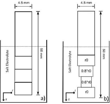
With the purpose of detecting any outgassing of hydrogen after charging, two samples were charged at 300 °C with 60 days between them, before being sent for hydrogen measurement analysis together with an uncharged reference. Measurement of hydrogen content in the samples was carried out at Swerea KIMAB, Sweden, with a LECO Rhen 602 thermal conductivity detection system. This method of measurement registers the full content of hydrogen within the sample, and does not distin-guish between hydrogen located in a trap sites or in a lattice sites. The charged samples were cut into three smaller segments corresponding to different depths (z) in the electrolyte, with the topmost seg-ment being submerged at least 2–3 mm into the molten salt, see Figure 2a. The following charging procedures were performed at 250 °C. These samples were cut in a similar manner, but the segments were first carefully lathed down to 0.8 and 0.6 times the initial radius, r0 = 2.25 mm, see Figure 2b.
Figure 2. Schematic showing how the charged samples were cut in smaller segments (a), or lathed and cut (b), before hydrogen measurement, with the purpose of revealing any longitudinal or radial concentration gradients.
To evaluate the extent of surface degradation because of cathodic charging, the surface was ex-amined using scanning electron microscopy (SEM) in a Hitachi SU-8010 instrument.
4. Computed Hydrogen Profile
The general time dependent diffusion equation (Fick's second law) reads
(1)
where C is the concentration of the diffusing element and D the diffusion coefficient. The diffusion coefficient is defined as , where R and T are the gas constant and absolute temperature, respectively. An activation energy HD for hydrogen diffusion in IN718 of 48.63 kJ/mol
was assumed [25]. The pre-factor, D0 has a reported range of 1.6–6.16 × 10⁻⁷ m2/s [25,26,27]. These
reported coefficients are based on results of hydrogen permeation tests on IN718, either by gas permeation or electrochemical cells. These results have to be seen as a mixture of hydrogen transport both in normal interstitial lattice sites (NILS) and in reversible trap sites. The seemingly wide span of the range can be explained by the higher density of trap sites within precipitation hardened compared to annealed IN718 [26]. In this evaluation of the charging method there is no direct need to distin-guish between trap site diffusion and NILS diffusion. For this reason we have chosen a value of D0 =
4.0 × 10⁻⁷ m2/s, which is close to the results from gas permeation test results and the value used in previously perfomed chargings, even if not gas-charged [3,15].
To calculate specific concentrations at various diffusion lengths using a solution to Eq. (1), the surface concentration of atomic hydrogen must be determined. If hydrogen gas charging methods are used, Sievert's law gives a good estimate [16]. However, for cathodic charging methods, the calcula-tions are more complex. Any analytical solution regarding surface concentration of available hydro-gen during a cathodic charging process is based on temperature, applied electric potential, proton conductivity of the electrolyte, and the electrochemical reaction. As with any charging method, the mechanism is also to some extent dependent on the surface chemistry and topology of the sample, as this may influence the dissociation rate of molecular hydrogen into atomic hydrogen, before entering the sample [28,29,30]. In addition, many of these factors may change during the charging process. The complexity of this evaluation and the difficulties of obtaining trustworthy results have been hig-hlighted in a previous evaluation of the cathodic charging method [20]. In order to estimate the time needed for hydrogen to reach the center of the sample during cathodic charging, approximate calcu-lations based on are commonly found in the literature. Furthermore, this estimate is based on a diffusion constant in which only concentration driven diffusion is considered [3,14,15,31]. This results in a grossly overestimated charging time and underestimated diffusion length of hydrogen, which could lead to questionable conclusions regarding the hydrogen effect on the embrittlement mechanisms [23].
During cathodic charging, diffusion is not only driven by the concentration gradient, but also by electromigration because of the applied electric potential. The calculated potential drop in the length of the conducting sample rod is negligible, and its surface could be considered as an isopotential. The movement of the charge carriers close to the sample surface (e.g. migrating hydrogen ions), is as-sumed to follow the electric field in the electrolyte, which is approximately radial. Longitudinal dif-fusion, perpendicular to this electric field, is thus practically only concentration driven. When elec-tromigration is considered, the diffusion coefficient is reportedly scaled by the elecelec-tromigration fac-tor [32], which is multiplied by the component j of the charging current density vecfac-tor j in the di-rection of the flux, and the sample radius r0. This anisotropic behavior of the diffusion coefficient is
represented in the computation as a symmetric matrix in cylindrical coordinates with
(2)
and
(3)
The electromigration factor is defined as
(4)
where Z* is the effective charge number of the migrating particle. The resistivity, , for IN718 at 300 °C is measured to be around 1.32 × 10⁻⁶ Ωm [33]. Further, e is the electron charge with 1.602 × 10⁻¹⁹ C, and k is the Boltzmann constant. Z* is a dimensionless, experimentally determined parameter, which is a summation of the direct electrostatic force and the electron wind force. For H+ the effective charge number in an NbV alloy was found to be close to unity, and not reported to be sensitive to temperature or to variations in alloy composition [34]. No value has to our knowledge been reported for H+ in Ni-based alloys, but for pure Ni a value of 0.5 has been quoted, and
investi-gations on various polycrystalline metals as well as several alloys, report values of 0.4–1.6 [35,36]. In this work we will assume Z* = 1.
For evaluations of the anisotropic diffusion process, e.g. were both radial and longitudinal diffu-sion are considered, a finite volume PDE solver, FiPy, is used [37]. Computations are based on Eq. (2–3) in two dimensions, corresponding to an axisymmetric cylidrical grid, with a mesh of 50 × 1000 squares, all with a side length of 50 μm. A small enough time step is chosen to assure stable solutions. Computations are performed for different charging times, in order to show the anisotropic effect when electromigration as a driving force is considered. They are solved assuming the same hydrogen concentration for both bottom and outside surfaces. The top surface of the sample, representing the surface outside the electrolyte, is given a zero concentration of hydrogen.
Table 2. Parameter values used in the computations.
Parameter
Used value 4.0×10⁻⁷ 48.63×10³ 8.314 1 1.602×10⁻¹⁹ 1.32×10⁻⁶ 1.38×10⁻²³
5. Results
The results are presented in two subsections, divided between the experimental results of hydrogen measurement and SEM imaging, and the theoretical results with calculations and computations.
5.1. Charging results
The hydrogen concentration measurements for the samples charged at 300°C are presented in Figure 3. The mean depth in the electrolyte corresponds to the the way the samples were cut (Figure 2) before measurement. Our charging result does not reveal any clear difference in the hydrogen content that can be directly related to the period of time between the charges. As the concentration of hydrogen is slightly higher in the samples that had longer holding times between charging and analysis, any difference in concentration is believed to be a result of fluctuations in charging parameters. This is in good agreement with reported work [38] in which no outgassing of the previously introduced hydrogen could be detected for samples stored at room temperature for up to a year. Measurements on a reference, uncharged samples, gave a hydrogen concentration of 0.1–0.3 wt ppm.
The results reveal a concentration gradient as a function of depth in the charging electrolyte. Based on the resistivity of IN718, the calculated potential drop within the sample from bottom to top during charging is negligible. The surface of the sample could therefore be considered as an isopotential, and therefore no large longitudinal gradient in the electrical potential is expected and therefore is not believed to be the source for the concentration gradient. This analysis does not take into account the fact that although the density of positive charge carriers is assumed to be almost homogeneous within the length of the sample, there could still be a gradient of positively charged hydrogen ions related to other positive charge carriers. This would require an uneven distribution of
available hydrogen at the sample surface during charging, which is believed to be the cause of the resulting longitudinal concentration gradient. The reason for this thought uneven distribution could be an easier evaporation of hydrogen closer to the electrolyte surface. The reported measurements of the charging performed at 250 °C can be seen in Figure 4. These samples were lathed and cut according to Figure 2b, for radial concentration analysis. The result is normalised according to the depth gradient for an easier display of the hydrogen content at different radii in the sample. Because of machining issues, the reduced radius could not be evenly divided over the whole sample length. Measurements of the concentration for the reduced radius do not provide support for any radial concentration gradient.
Figure 1. Measured hydrogen content of samples charged at 300 °C and cut according to different depths into the electrolyte. The linear fits have slopes of 0.10 and 0.09 respectively.
Figure 2. Measured hydrogen content of samples charged at 250 °C, lathed down to different radii and cut according to different depths into the electrolyte. The linear fit has a slope of 0.15.
Electron microscopy imaging of a sample charged at 250 °C and an uncharged reference reveals changes in surface topology as a result of the charging1. Magnifications are 40x (Figure 5) and 1000x (Figure 6) Reviewing the images, the charging induced degradation seems to be surface localized with an effective depth of around 10 μm.
a) b)
Figure 5. SEM image of the exposed surface of the sample before and after charging, marked for clarification. Images recorded at 40x magnification.
b) b)
Figure 6. SEM image of the exposed surface before and after charging, marked for clarification. Images recorded at 1000x magnification.
5.2. Computed hydrogen concentration profile
With an average current density of 0.6 mA/mm2, a charging temperature of 250 °C, a sample radius of r0 = 2.25 mm, and with the electromigration parameter values given in Section 4, the
1
The observed alteration of the surface topology is likely also responsible for alteration of the surface chemistry. This will to some degree change the rate of hydrogen uptake, but any further analysis regarding this change has not been undertaken.
diffusion coefficient for radial diffusion is calculated (Eq. (5)). This is almost 12 times larger than the coefficient when electromigration is not considered (Eq. (6)).
(5)
(6)
For a circular symmetrical cylinder of infinite length, where both constant surface concentration,
Cs, and an initial specimen concentration of zero are assumed, the solution to Eq. (1) is:
(7)
where J0 and J1 are the Bessel-functions of zeroth and first order with being the
roots of J0. This solution can be used to calculate the concentration ratio as a function of the radius
for varying values of the normalised time, . If electromigration is not considered, the normalised time, based on a charging time of 25 h, would in our case be . Using the modified diffusion coefficient, , and the experimental charging parameters, instead gives . The resulting concentration profiles for the two cases are shown in Figure 7. With electromigration as a driving force, and the charging parameters mentioned the resulting hydrogen concentration would be completely homogeneous, which agrees with the experimental measurements in Figure 4. If electromigration is not considered, the calculated radial concentration gradient would yield a 50% lower concentration of hydrogen at 0.6 r0 than at r0; a case that is not seen in the
measurement result.
Figure 7. Radial concentration ratio profiles C/Cs, calculated using Eq. (7) for different
normalised times with electromigration considered ( or not ( .
The cross-section profiles of the finite volume computation for the charging times of 4 and 25 h can be seen in Figure 8a and Figure 8b, respectively. In both computations the experimental parameters of Table 2 are used. Based on the measured results of the charging, a hydrogen
concentration of 5 wt ppm H is set as boundary conditions for the bottom end and outside surfaces, while the top surface has a boundary condition of 0 wt ppm H. The resulting figures are cut in the middle for more convenient display. The computations verify the expected hydrogen homogeneity for the 25 h charging when electromigration is also a factor. The computation for a 4 h charging time reveals the profound effect electromigration has on the diffusion length of hydrogen into the sample. In either of the cases, it is evident that the longitudinal gradient found in the measured results can not be explained by the additional diffusion from the bottom surface.
Figure 8. Comparative hydrogen concentration computation with either an isotropic D (where all diffusion is only concentration driven) or an anisotropic D (where the radial diffusion is both concentration and electromigration driven). The computations are performed for charging times of 4 h and 25 h in a) and b), respectively.
6. Discussion
Although some literature on charging IN718 with hydrogen using various methods lack mea-surements of the resulting hydrogen concentrations [15,39,40], Hicks [41] charged IN718 samples using atmospheric pressure of pure hydrogen gas and reported a resulting concentration of 40 wt ppm. Hicks and Altstetter [7] further reported a concentration of 50 wt ppm, while Liu et al. [3,14,31] measured a hydrogen concentration of 20 wt ppm, after charging IN718 samples using cathodic charging. Reviewing the measured hydrogen concentration of this study, the charging result is up to 10 times lower. Even though the charging procedure and parameters used were almost identical to the work of Liu et al., the result is almost 4 times lower. Whether this is an effect of the conducted charging procedure or the subsequent measurement of introduced hydrogen, is hard to conclude. Even if the resulting mean concentration of introduced hydrogen is lower than expected, the hydro-gen content is still almost 20 times higher than in the uncharged reference sample. Meaning that ap-proximately all of the measured hydrogen in the charged samples, is a result of the cathodic charging.
If the content is high enough to be able to study the effect on the tensile response in general, and the HELP mechanism specifically, will be evaluated in coming work. A longitudinal concentration gra-dient after charging is, to our knowledge, not mentioned in the literature on cathodic charging.
Loosely introduced hydrogen close to the surface of the sample, most likely escapes as soon as the enhanced surface concentration of hydrogen reverts (e.g. the charging procedure is terminated). This is followed by a continuous outgassing of hydrogen residing in NILS, which could be difficult to detect. The reason for this difficulty is the relatively slow lattice diffusion at room temperature. But it can also be explained by the high density of trap sites in precipitation hardening alloys, such as IN718 [26], which reduces the amount of hydrogen residing in NILS.
In the reviewed literature on cathodic charging of IN718, the surface degradation side effect is only addressed by Fournier et al. [15], while charging using a H2SO4 solution. Surface degradation is
not mentioned as problematic in the sense of masking the examination of the hydrogen effect on the tensile response. For the reviewed literature on experiments with IN718 cathodically charged in mol-ten salt, the surface effects are not reported as having any direct effect on mol-tensile test results. Obtain-ing a relatively high and homogeneous concentration of hydrogen in the sample has on the other hand been concluded to alter both the fracture mode and fracture surface topology when conducting tensile tests [7,14,41].
Although the measured results regarding radial distribution cannot be used to explicitly confirm the calculations and computations, they give an indication towards radial concentration homogeneity. This means that diffusion is not solely concentration driven, and electromigration has to be ac-counted for. Any validation regarding the electromigration parameters used in connection with the experimental results is beyond the scope of this study. As the electromigration factor theoretically scales the radial component of the diffusion constant by almost 12 times, the longitudinal component of the diffusion constant (e.g. the diffusion from the bottom of the sample) will have little effect on the resulting concentration profile. To assume an infinite rod, for easier calculations, can be consi-dered safe, especially if the length of the sample is appreciably larger than its radius. This means that Eq. (7) can be used to optimize the charging time needed to gain the desired outcome. Given the cor-rosive nature of the charging method, although the degree of impact that this surface degradation has on the following mechanical testing is not determined, it is desirable to keep the charging time as low as possible.
7. Conclusions
It has been shown that the driving force for hydrogen diffusion during cathodic charging cannot solely be explained by a concentration gradient, and that the applied electric potential must be ac-counted for. This is dealt with by implementing electromigration in the description of the diffusion process, which helps to more accurately estimate the required charging time and minimize any un-wanted side effects of the charging. Furthermore the degradation caused by charging is shown to be surface localized and could readily be polished away before any mechanical test is performed, and should not alter a tensile test outcome in any substantial way.
Acknowledgements
This work was carried out with financial support from the Swedish Research Council, grant 621-2012-3698. The authors would also like to thank Olof Hultin at Solid State Physics, Lund Uni-versity, for assistance in SEM imaging, and Dr. Tautgirdas Ruzgas at Malmö University for initial setup discussions.
Conflict of Interest
All authors declare no conflict of interest in this paper.
References
1. Slama C, Abdellaoui M (2000) Structural characterization of the aged Inconel 718. J Alloy
Compd 306: 277–284.
2. Reed RC. 2. The Physical Metallurgy of Nickel and its Alloys, In: Superalloys - Fundamentals
and Applications: Cambridge University Press.
3. Liu L, Tanaka K, Hirose A, et al. (2002) Effects of precipitation phases on the hydrogen embrit-tlement sensitivity of Inconel 718. Sci Technol Adv Mater 3: 335.
4. Hirose A, Arita Y, Nakanishi Y, et al. (1996) Decrease in hydrogen embrittlement sensitivity of INCONEL 718 by laser surface softening. Mater Sci Eng A 219: 71–79.
5. Sjöberg G, Cornu D (2001) Hydrogen Embrittlement of Cast Alloy 718 - Effects of Homogeniza-tion, Grain Size and delta-phase, 679–690.
6. Hicks PD, Altstetter CJ (1992) Hydrogen-enhanced cracking of superalloys. Metall T A 23: 237– 249.
7. Hicks PD, Altstetter CJ (1990) Internal hydrogen effects on tensile properties of Iron- and Nick-el-base superalloys. Metall T A 21A: 365.
8. Senor DJ, Peddicord KL, Strizak JP (1991) Effects of hydrogen on the fracture morphology of Inconel 718. Mater Lett 11: 373–378.
9. Birnbaum HK (1989) Mechanisms of hydrogen-related fracture of metals. Office of Naval
Re-search USN 00014-83-K-0468.
10. Dadfarnia M, Martin ML, Nagao A, et al. (2015) Modeling hydrogen transport by dislocations. J
Mech Phys Solids 78: 511–525.
11. Pound BG (1990) Hydrogen trapping in precipitation-hardened alloys. Acta Metall et Mater 38: 2373–2381.
12. Milella P (2013) Hydrogen Embrittlement and Sensitization Cracking, In: Anonymous Fatigue
and Corrosion in Metals: Springer Milan, 689–729.
13. Au M (2007) High temperature electrochemical charging of hydrogen and its application in hy-drogen embrittlement research. Mater Sci Eng A 454–455: 564–569.
14. Liu L, Zhai C, Lu C, et al. (2005) Study of the effect of delta phase on hydrogen embrittlement of Inconel 718 by notch tensile tests. Corros Sci 47: 355–367.
15. Fournier L, Delafosse D, Magnin T (1999) Cathodic hydrogen embrittlement in alloy 718. Mater
Sci Eng A 269: 111–119.
16. Oriani RA (1993) The physical and metallurgical aspects of hydrogen in metals. ICCF4 Fourth
International Conference on Cold Fusion.
17. Beloglazov SM (2003) Peculiarity of hydrogen distribution in steel by cathodic charging. J Alloy
Compd 356–357: 240–243.
18. Kimura A, Birnbaum HK (1987) The effects of cathodically charged hydrogen on the flow stress of nickel and nickel-carbon alloys. Acta Metall 35: 1077–1088.
19. Panagopoulos CN, Georgiou EP, Chaliampalias D (2014) Cathodic hydrogen charging of zinc.
Corros Sci 79: 16–20.
20. Ulmer DG, Altstetter CJ (1987) Hydrogen concentration gradients in cathodically charged auste-nitic stainless steel. J Mater Res 2: 305–312.
21. Birnbaum HK, Sofronis P (1994) Hydrogen-enhanced localized plasticity—a mechanism for hy-drogen-related fracture. Mater Sc Eng A 176: 191–202.
22. Raizman A, Barak J, Zamir D, et al. (1983) NMR study of hydrogen in cathodically charged In-conel 718. J Nucl Mater 119: 73–77.
23. Delafosse D, Magnin T (2001) Hydrogen induced plasticity in stress corrosion cracking of engi-neering systems. Eng Fract Mech 68: 693–729.
24. Hamma H, Rasmussen SB, Rogez J, et al. (2006) Conductivity, calorimetry and phase diagram of the NaHSO4–KHSO4 system. Thermochim Acta 440: 200–204.
25. Xu J, Sun XK, Liu QQ, et al. (1994) Hydrogen Permeation Behavior in IN718 and GH761 Supe-ralloys 25A: 539–544.
26. Jebaraj JJM, Morrison DJ, Suni II. (2014) Hydrogen diffusion coefficients through Inconel 718 in different metallurgical conditions. Corros Sci 80: 517–522.
27. Turnbull A, Ballinger RG, Hwang IS, et al. (1992) Hydrogen Transport in Nickel-Base Alloys 23A: 3231–3244.
28. G A, C B. (1998) Surfaces, Oxford Chemistry Primer 59 Eds., Oxford: Oxford University Press. 29. Kupka M, Stępień K, Nowak K (2014) Studie on hydrogen diffu ivity in iron aluminide u ing
the Devanathan–Stachurski method. J Phys Chem Solids 75: 344–350.
30. ASTM (2011) Standard Practice for Evaluation of Hydrogen Uptake, Permeation, Transport in Metals by an Electrochemical Technique G148-97.
31. Liu L, Tanaka K, Hirose A, et al. (2003) Experimental and numerical analyses of the mechanism for decreasing hydrogen-embrittlement sensitivity of aged Inconel 718 by laser surface annealing.
J Laser Appl 15: 134–144.
32. Chao B, Chae S, Zhang X, et al. (2007) Investigation of diffusion and electromigration parame-ters for Cu–Sn intermetallic compounds in Pb-free solders using simulated annealing. Acta Mater 55: 2805–2814.
33. Basak D, Overfelt RA, Wang D (2003) Measurement of Specific Heat Capacity and Electrical Resistivity of Industrial Alloys Using Pulse Heating Techniques. Int J Thermophys 24: 1721– 1733.
34. Brouwer RC, Griessen R (1989) Electromigration of hydrogen in alloys: Evidence of unscreened proton behavior. Phys Rev Lett 62: 1760–1763.
35. Ho PS, Watson TS (1989) Electromigration in metals. Rep Prog Phys 52: 301–348.
36. van Ek J, Lodder A (1994) Electromigration of hydrogen in metals: Theory and experiment.
De-fect and Diffus Forum 115–116: 1–38.
37. Guyer JE, Wheeler D, Warren JA (2009) FiPy: Partial Differential Equations with Python.
Com-put Sci Eng 11: 6–15.
38. Gray HR (1974) Embrittlement of Nickel-, Cobalt-, and Ironbase Superalloys by Exposure to Hydrogen TND-7805.
39. He J, Fukuyama S, Yokogawa K, et al. (1994) Effect of Hydrogen on Deformation Structure of Inconel 718. Mater T JIM 35: 689–694.
40. Dong J, Zhang M, Xie X, et al. (2002) Interfacial segregation and cosegregation behaviour in a nickel-base alloy 718. Mater Sci Eng A 328: 8–13.
41. Hicks PD (1990) Hydrogen embrittlement of selected nickel and iron-base superalloys. ProQuest
Dissertations and Theses.
© 2016 Niklas Ehrlin, et al., licensee AIMS Press. This is an open access article distributed under the terms of the Creative Commons Attribution License (http://creativecommons.org/licenses/by/4.0)