Zedboard based platform for condition
monitoring and control experiments
Anders Adrielsson
Computer Science and Engineering, bachelor's level
2018
Luleå University of Technology
i
Abstract
New methods for monitoring the condition of roller element bearings in rotating machinery offer possibilities to reduce repair- and maintenance costs, and reduced use of environmentally harmful lubricants. One such method is sparse representa-tion of vibrarepresenta-tion signals using matching pursuit with dicrepresenta-tionary learning, which so far has been tested on PCs with data from controlled tests. Further testing requires a platform capable of signal processing and control in more realistic experiments. This thesis focuses on the integration of a hybrid CPU-FPGA hardware system with a 16-bit analog-to-digital converter and an oil pump, granting the possibility of collecting real-time data, executing the algorithm in closed loop and supplying lubrication to the machine under test, if need be. The aforementioned algorithm is implemented in a Zynq-7000 System-on-Chip and the analog-to-digital converter as well as the pump motor controller are integrated. This platform enables portable operation of the matching pursuit with dictionary learning in the field under a larger variety of environmental and operational conditions, conditions which might prove difficult to reproduce in a laboratory setup. The platform developed throughout this project can collect data using the analog-to-digital converter and operations can be performed on that data in both the CPU and the FPGA. A test of the system function at a sam-pling rate of 5 kHz is presented and the input and output are verified to function correctly.
iii
Acknowledgements
I would like to thank my supervisors, Sergio and Fredrik for their patience and pro-fessionalism. I also stand in gratitude to my family, relatives and friends for their encouragement and support.
v
Contents
1 Introduction 1
1.1 Matching pursuit with dictionary learning . . . 1
1.2 Platform specification. . . 3
1.3 Platform requirements . . . 4
1.4 Delimitations . . . 4
2 Methods and hardware 5 2.1 Hardware components . . . 5
2.2 Protocols and development tools . . . 7
3 Results 9 3.1 Programmable logic configuration . . . 9
3.1.1 Integrating peripherals. . . 11
3.2 Processing system software . . . 13
3.2.1 Interfacing peripherals . . . 14
4 Discussion 17 4.1 Further work. . . 19
vii
List of Abbreviations
ADC Analog (to) Digital Converter AXI Advanced eXtensible Interface BSP Board Support Package CPU Central Processing Unit
EMIO Extended Multiplexed Input Output FPGA Field Programmable Gate Array GPIO General Purpose Input Output HDL Hardware Description Language IP Intellectual Property
MIO Multiplexed Input Output Pmod Peripheral module Interface RTL Register-Transfer Level SPI Serial Peripheral Interface
1
Chapter 1
Introduction
Condition monitoring is the process of observing a set of parameters of a machine or component (vibration or temperature for instance) and from that draw a conclusion about its functional condition. Based on that conclusion, actions such as supplying lubricant may be performed to alleviate the problem or prevent a more serious one from developing.
Modern industry use automated lubrication systems to reduce labor- and down-time costs related to their rotating machinery. These systems typically rely on basic sensory information such as critical level alarms and human expert opinions based on assumptions and generalizations about the operating conditions of the rotating components. This uncertainty increases the risk of over- or under-application of lu-bricants. Under-greasing can result in premature wear that may lead to a complete breakdown of the affected part. Over-greasing can lead to churning which results in energy loss in the form of heat, causing oxidation and thus degradation of the grease [1]. An excessive amount of grease around the bearing already hinders heat dissipation, further increasing temperature and degrading the lubricant, ultimately causing premature wear [2].
Research performed at Luleå University of Technology in the University Technol-ogy Center (UTC) in conjunction with AB SKF on the subject of machine learning for condition monitoring has produced promising results that motivate further in-vestigations [3]. A matching pursuit algorithm together with dictionary learning creates a sparse representation of the vibration signal measured near a bearing. The resulting sparse code and learned waveforms produce measurements that can be used in the diagnosis of the bearing health under varying operating conditions. This method is intended to prevent bearing failure and reduce the amount of lubricant used in rotating machines compared to regular lubrication systems with predefined settings or rudimentary sensory systems. Additionally, this approach should reduce the amount of intervention by human experts.
This report presents an implementation of this method on a platform which aim is to extend the testing capabilities beyond offline data analysis (offline referring to non-real-time).
1.1
Matching pursuit with dictionary learning
What follows is a basic overview of the matching pursuit algorithm used to moni-tor the condition of rotating machinery. With it, the characteristic vibration signal recorded by a sensor can be learned. Indicators in the learned dictionary thereafter could indicate a change in condition of the rolling element bearing in the machine [18] (Chapter 5).
2 Chapter 1. Introduction
A common practice in condition monitoring is to manually define what a malfunc-tion may look like in terms of data collected from the machine. Simply put, experts state what features of a signal indicate a malfunction. The correlation between these features and the actual condition is however subject to change throughout the lifes-pan of the machine and its operating conditions, and might vary from machine to machine of the same type. A machine learning approach to the feature extraction may increase relevancy of the chosen features since they are extracted from each machine individually.
Matching pursuit is a sparse coding algorithm that represents a signal as a lin-ear combination of waveforms. When properly sequenced and added together the waveforms can approximate the actual input signal. The benefit of a sparse signal representation is the ability to process it in resource constrained hardware, as use-ful results can be obtained from as low as 2.5% - 10% of the original data set [3]. By updating the dictionary of learned features, a stable representation of the sig-nal character is obtained. Furthermore, by observing indicators in the dictionary, a change in the machine’s condition can be deduced.
Matching pursuit with dictionary learning is one well-known algorithm for decom-posing a sampled signal in terms of learned functions. These functions are wave-forms (from here on referred to as atoms) with compact support that are randomly initiated from a Gaussian distribution. The set of atoms define a dictionary that is constantly adapted to the signal. The following roughly describes the matching pur-suit with dictionary learning process:
A vibration signal is measured by a sensor at some location on the machine with a preselected sampling frequency. The signal is cross-correlated with all atoms in the dictionary which is updated thereafter, as follows:
Starting from the first discrete element of the sampled signal, an atom is selected and its dot product with the signal from that location and forwards is calculated. This is done with normalized values. The dot product shifted one sample at a time along the length of the signal is subsequently calculated. This is repeated until a number of dot products (from here on referred to as weights) have been produced throughout the entire length of the sampled signal. This process is known as a slid-ing dot product. The dot product yields the similarity of two vectors, a larger weight indicates greater similarity. This is done for all atoms in the dictionary.
The atom number, maximum weight and the location (referred to as index) in the signal where the maximum weight was calculated is saved.
1.2. Platform specification 3 The best matching atom is then subtracted from the signal at the specified index and the residual is the input signal for the next iteration of the process. The se-lected atom, its corresponding weight and the index in the residual where the atom is subtracted is entered into an event table. When a stopping condition is met, for in-stance a certain number of iterations or a threshold residual root mean square value is reached, the dictionary is adapted with regards to the event table. Otherwise, the matching pursuit is performed again and the event table extended with a new best match entry, checking for the stopping condition once more.
The dictionary learning process uses the event table and the residual to modify the atoms in the dictionary. In essence, the amount of atom modification depends on the shape and variance of the residual after the stopping condition has been met. This is done with the algorithm described by Sandin & Martín del Campo [3].
1.2
Platform specification
Hardware for the project was provided by UTC and the aim of it is to produce a portable implementation of the matching pursuit with dictionary learning rithm. The platform shall contain an implementation of the matching pursuit algo-rithm on digital hardware and an accelerometer sensor that measures vibrations in proximity to the bearings being analyzed.
Sandin, Martín del Campo, Nilsson & Eliasson [4] show that when matching pur-suit is executed on a Central Processing Unit (CPU), about 98% of processing time is spent on the cross correlation-part of the algorithm. A Field Programmable Gate Array (FPGA) can significantly speed up the processing time of this step thanks to its parallelization capabilities. However, a CPU is better suited due to its ease of use and traditional programming flexibility during testing and analysis.
With this taken into consideration, UTC has provided this project with a Zedboard development board with a Xilinx Zynq-7000 System-on-Chip as its main computing component. The Zynq-7000 contains a dual core ARM Cortex A9 CPU and an Artix-7 FPGA.
Vibrations are measured by an industrial-grade accelerometer, model SKF-607M69. This component is secured to the bearing support structure. A 16-bit resolution Maxim Integrated Santa Fe Analog Front End reads the analog vibration signal from the accelerometer. The Santa Fe is a high resolution analog-to-digital converter (ADC) that converts the voltage output from the sensor to a digital representation understood by the Zedboard.
The oil pump is a basic hobby grade RC plane fuel pump operating at 12 V. In ad-dition, a control mechanism for the pump is needed as the pump operates at much higher voltage and current than any conventional development board could deliver. A Digilent OD1 open drain output was given for this purpose to control peripherals that utilize an external power supply.
4 Chapter 1. Introduction
1.3
Platform requirements
Using the aforementioned hardware setup, the following steps must be performed in order to fulfill the intended purpose of making a machine learning platform capable of anomaly detection and reinforcement learning of effective lubrication strategies:
• Enable data transfer and data synchronization between CPU and FPGA. • Establish communication between the ADC and the Zedboard.
• Program the matching pursuit HDL module onto the programmable logic of the Zynq chip.
• Create a basic program for sampling the vibration signal, run the matching pursuit algorithm on the data, perform the dictionary learning process and present the results.
• Establish communication between the Zedboard and the OD1 open drain out-put module.
• Create a decision making process that activates the pump based on dictionary indicators.
1.4
Delimitations
Components have been evaluated and chosen prior to this thesis work.
A custom HDL implementation of the matching pursuit will not be made, as one has already been created in another effort. It was created using Vivado HLS (see section 2.2.2), and will be integrated into this project as best possible.
Some code for transferring data between the processing system and the programmable logic has been supplied.
The ADC chosen comes with its own firmware, how accommodating it is to the needs of this project is unclear.
An anti-aliasing filter is needed in between the ADC and the vibration sensor but will not be a part of this thesis. The filter’s use is motivated in Chapter 2.
The SKF accelerometer SKF-607M69 was in use by UTC prior to this project and is not discussed further.
Evaluating different decision strategies and such will also not be done, a suggested reinforcement learning technique called Q-learning has been given by the supervi-sors of this thesis.
5
Chapter 2
Methods and hardware
2.1
Hardware components
A Zedboard development board [5] with a Xilinx Zynq-7000 (XC7Z020-CLG484-1) was provided as the basis for the platform. The Zedboard incorporates volatile RAM and persistent FLASH memory, buttons, switches, an OLED screen, Ethernet con-nectivity and several interfaces for peripherals. The main component of the board, the Zynq-7000, features a dual-core ARM Cortex-A9 processor coupled with a Xilinx Artix-7 FPGA along with modules and connections devoted to efficient communica-tion between the two. On the Zedboard are five Pmod connectors which are General Purpose Input/Output (GPIO) interfaces defined by Digilent Inc [6]. The Pmod is a 2x6 pins connector.
The FPGA is used for the cross correlation part of the matching pursuit algorithm. The dictionary learning algorithm is performed in the CPU.
In short, programming an FPGA involves writing code in a Hardware Description Language (HDL) defining a digital circuit and its structure/behavior, after which a design tool synthesizes and verifies the design, ultimately generating a bitstream with which the programmable logic is configured. The configuration is volatile, meaning the FPGA will be completely unprogrammed if the power is turned off. This is why a separate memory device is typically loaded with the bitstream and automatically programs the FPGA each time the device is turned on. Compared to a general CPU, the hardware implemented on an FPGA is task specific and optimized to execute actions in parallel, significantly increasing performance.
The ADC is a Santa Fe Analog Front End (MAXREFDES5#) [7] by Maxim Integrated. It has a 16 bit resolution and features inputs accepting voltages ranging from ±10 V and currents between 4 mA and 20 mA. The main component in the Santa Fe Ana-log Front End is the MAX1301 chip. The ADC communicates via the SPI protocol through the Pmod interface. Firmware is available from Maxim’s product page [14]. When sampling analog signals, an anti-aliasing filter for cutting off high frequen-cies must be used between the vibration sensor and the ADC. The Nyquist-Shannon sampling theorem states that the sampling rate must be at least twice that of the highest frequency component of the signal being sampled. Aliasing occurs when this criterion is not satisfied. Aliasing is when data points from a much higher fre-quency signal are mistaken in the sampled signal for being of a lower frefre-quency. The filter will be disregarded in this thesis, however.
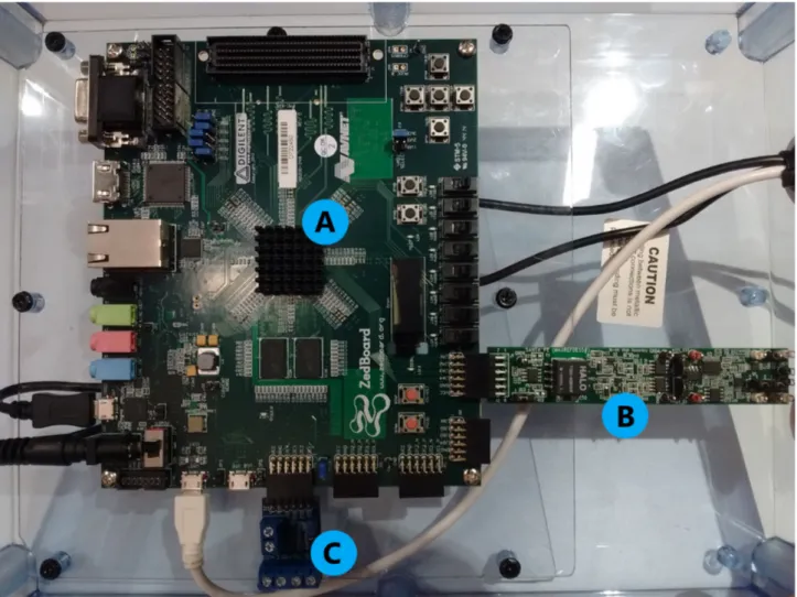
6 Chapter 2. Methods and hardware The pump controller is a Digilent OD1 [8] open drain output with four different outputs independently controlled by the host board through a Pmod connector. The OD1 can sustain up to 20 V and 3 A continuously which is plenty for this application. Figure2.1illustrates the Zedboard with the peripherals enumerated.
FIGURE2.1: The Zedboard-based platform in its plastic housing. A — ZYNQ-7000, main computer chip (underneath cooling fins). B — Maxim Santa Fe AFE, analog-to-digital converter.
2.2. Protocols and development tools 7
2.2
Protocols and development tools
The Maxim Santa Fe ADC uses the Serial Peripheral Interface (SPI) to communicate with other devices and the Zedboard supports many communication protocols in-cluding SPI.
SPI is a synchronous serial communication bus commonly used for microcontroller and peripheral communication. Two nodes communicate at a time, one being the master that initiates the communication and the other being the slave. It is full du-plex, meaning both nodes send and receive data simultaneously. It generally consists of four signals.
To program the components of the Zedboard multiple software applications are needed. In the case of this report, the development process can be divided into three different stages and applications used.
Vivado
Xilinx Vivado [9] is used to configure the programmable logic, allowing for analysis and synthesis of HDL-designs.
This is the second step of the development process (the first being physically inter-connecting the devices), where peripherals, processing units and other HDL mod-ules are created and coupled together in the programmable logic. Aspects of the ARM Cortex A9 CPU in the Zynq chip as well as its built-in modules are configured, along with connections to ports on the Zedboard itself. Programming of the FPGA is done using Vivado, it comes with many board presets which allows it to commu-nicate with the Zedboard without much user intervention. A 1-year Vivado license came with the purchase of the Zedboard but there are free versions available too.
Vivado HLS
Vivado High-Level Synthesis [10] allows for the creation of HDL modules targeted at Xilinx devices to be used in Vivado without having to explicitly develop them in a hardware description language. Higher abstraction languages like C or C++ can be used to describe an algorithm, reducing the risk of errors and also speeding up development. Vivado HLS will not be used per se in this project, but rather the matching pursuit module it has produced in an earlier effort will be imported into Vivado as an external Intellectual Property (IP).
Xilinx SDK
Xilinx Software Development Kit [11] is the integrated development environment where the programming of the processing system is performed.
It is based on the Eclipse integrated development environment in which C or C++ can be used to write the software running on the Zynq chip’s dual-core CPU. Based on which peripherals in the Zynq-7000 are active and what HDL modules are pro-grammed onto the programmable logic, device drivers with which to control these through software are generated and made available. Interaction between programmable logic and software executing in the processing system is done through custom func-tion calls, defined by said drivers. Other aspects of the CPU are configured at this stage, and XSDK also handles the transferring of the executable program file to the Zedboard.
9
Chapter 3
Results
The processing system and the programmable logic of the Zedboard’s Zynq-7000 chip can be used individually but for this application they will be used in conjunc-tion. Nevertheless, they are programmed separately using different development tools. Section 3.1 describes the programmable logic configuration, section 3.2 the processing system programming. Both sections touch upon the integration of the ADC — the physical and communicative aspect respectively — likewise in the case of the OD1 pump controller.
3.1
Programmable logic configuration
ArchitectureThe programmable logic configuration and programming of the platform was done using Xilinx Vivado 2015.4 and Xilinx Vivado HLS 2015.4 with the product license obtained through the Zedboard purchase. The matching pursuit HDL module was created in Vivado HLS and imported into Vivado as an Intellectual Property (IP) and integrated with other IPs.
Vivado features an optional design method called a block design. In this graphical user interface, IPs are linked together to be implemented in the programmable logic. An IP is predefined logic that performs particular task, which source code generally cannot be accessed.
Figure3.1shows the block design. Rectangles represent IPs and lines represent con-nections in between. In the design there are six modules in total.
• ZYNQ7 Processing System.
Vivado’s interface around the processing system of the Zynq and the logic connection between the processing system and the programmable logic. In-put/Output, interrupts, clocks, memory and such are configured with this module.
• Matching Pursuit_original (Pre-Production).
This is the matching pursuit module describing the hardware executing the cross-correlation and generating the event table needed to perform the dictio-nary learning.
• AXI GPIO.
Two AXI General Purpose Input/Output modules are present, one controlling the inputs and the other monitoring the outputs to the matching pursuit mod-ule.
10 Chapter 3. Results • Processor System Reset & AXI Interconnect.
These modules connect all others with common clock- and reset-lines. These modules are automatically added and connected by Vivado when a ZYNQ7 Processing System module and other IPs are present in the design.
FIGURE 3.1: Vivado block design of the Zedboard-based platform,
blocks representing HDL modules (IPs).
The ap_done output signal from the matching pursuit module is connected to the PS7-module’s Core0_nIRQ pin in order to trigger an interrupt when the cross-correlation finishes. Alas, this does not trigger as intended, for reasons explored in Chapter 4.
3.1. Programmable logic configuration 11
3.1.1 Integrating peripherals
To communicate with external peripherals, the inputs and outputs of the Zynq need to be configured. The platform has two components in addition to the Zedboard, the ADC and the pump controller OD1, both connected to Pmod sockets on the Zed-board. The Zedboard Pmods connect through the Zynq’s Multiplexed Input/Output (MIO) and Extended MIO (EMIO) pins.
Analog-to-Digital Converter
The Maxim Santa Fe AFE communicates via an SPI interface. The ADC is connected to the programmable logic through the EMIO pins, via Pmod port JA1 on the Zed-board. EMIO is selected as the SPI’s I/O option, signifying which physical connec-tions will be used to transmit the data.
Lifted from comments in the Maxim Santa Fe firmware [14] (Code documentation V02.00, sections 5.10.3 & 5.11.2), the Zynq’s SPI clock is set to 114.287513 MHz. When enabled, an SPI bus shows up on the perimeter of the PS7-module in the block design which can be connected to another module accepting it. However, since the ADC is a physical device and not an IP in the block diagram, this connection is made external. The external signal bus constituting the SPI interface requires routing onto the phys-ical pins of the Zynq for it to connect to the ADC. The Xilinx errata AR# 47511 [12] discloses an error when using SPI with the SS0 signal (spi_1_ss_io) on the Zynq, therefore SS1 (spi_1_ss1_io) is used instead. The Zedboard hardware user’s guide [15] (section 2.9.2) specifies which pins of the Pmods connect to the pins of the Zynq chip. Each row of the 2x6 pins Pmod has a power pin and a ground pin, hence the exclusion of pins JA- 5, 6 & 11, 12 in the table. The JA Pmod pin mappings onto the Zynq are shown to the left in Figure3.2. The Maxim Santa Fe Analog Front End documentation [16] (p. 2) describes the configuration of the ADC pins of the male Pmod header attached to it, denoted J1 in the same Figure3.2.
FIGURE3.2: Pmod JA1 EMIO pin mappings and ADC pin configura-tion.
12 Chapter 3. Results
Vivado signal Zynq-7000 pin ADC pin
spi_1_io0_io AA11 MOSI
spi_1_io1_io Y10 MISO
spi_1_sck_io AA9 SCLK
spi_1_ss1_o Y11 CS
spi_1_ss2_o AB10 n/a (pin 8) spi_1_ss_io AB11 n/a (pin 7)
TABLE3.1: SPI connections between the Zynq’s EMIO pins and the ADC.
Looking at the mappings in Figure3.2 in conjunction with the enumeration of the Pmod pins (inscribed on the Zedboard), the correct routing of signals is entered in Vivado. The routing of the SPI signals to the ADC through the JA1 Pmod is shown in Table3.1.
Signals spi_1_ss_io and spi_1_ss2_o are connected to pins on the ADC that are not in use (pins 7 and 8) since they are not needed for this application. The SSTRB pin on the ADC is unconnected since the internal clock of the MAX1301 chip is not used.
OD1
The OD1, which controls the oil pump, is connected to the JE1 Pmod through the MIO pins. The MIO pins connect directly to the processing system (not through the programmable logic) and as such do not need to be routed as in the case of EMIO. In contrast to the ADC, the OD1 only connects to one row of the 2x6 pins Pmod connector. Figure 3.3 shows to the left which MIO pins connect to the JE1-Pmod pins and to the right the I/O diagram of the OD1. The indexing referred to as Signal Name and Signal is inscribed on the Zedboard and OD1 respectively.
FIGURE3.3: Pmod JE1 MIO pin mappings and OD1 pin description.
The Zynq pin column in Figure3.3is irrelevant in this instance since the MIO pins are already configured. The MIO pins are directly accessed through software drivers, at which point the appropriate entry in the MIO column is used as an argument. The hardware programming is complete when Vivado has successfully synthesized an implementation of the modules used in the block design in3.1and from that gen-erated a bitstream to configure the programmable logic in the Zynq chip with. A hardware description file is also generated to let Xilinx SDK create a Board Support Package (BSP). The BSP contains the hardware specifications, software libraries and drivers needed to control the hardware implemented in the programmable logic and the processing system.
3.2. Processing system software 13
3.2
Processing system software
Xilinx SDK 2015.4 was used to develop code for the processing system on the Zynq-7000. The software running on the platform is a standalone application, meaning there is no operating system in between the application and the hardware. One of the two processor cores in the Zynq’s processing system is used. The programming language used is C.
Summarily, the software developed for the platform works as follows:
1. A dictionary with eight atoms of fixed length is created. Preëxisting code for transferring these atoms to the matching pursuit module in the FPGA per-forms this task. Address pointers accessing shared memory regions between the CPU and FPGA make this possible.
2. The ADC samples the signal from the test rig at a given rate. When enough signal data to fill the buffer specified by the matching pursuit algorithm is col-lected, the data is transferred to the memory region reserved for the matching pursuit module. This transfer is performed by C’s memcpy-function.
3. A start-instruction to the AXI GPIO module controlling the matching pursuit module is issued. This is done through the GPIO driver supplied by the BSP. The cross-correlation of the signal and the atoms in the dictionary continues until a stopping condition is reached, and the matching pursuit procedure is complete. The memory address where the signal was initially located now contains the residual. Other memory areas reserved for the matching pursuit module contain the atoms and the generated event table with its indices and weights.
4. The dictionary learning function iterates through the atoms in the dictionary and updates them according to the event table and the residual. Throughout its execution, the dictionary learning reads and writes to the different addresses of the matching pursuit module in the FPGA, using pointers as previously mentioned.
5. Once the ADC has collected enough samples and the matching pursuit module has triggered the interrupt letting the processing system know it is complete, the cycle starts over, this time with the updated dictionary. As stated in Chap-ter 3, this triggering function does not operate properly and thus the program utilizes a suitable waiting period before issuing another start-command to the matching pursuit instead.
Dictionary learning is performed in the processing system (i.e the CPU), not in the programmable logic like the matching pursuit. The dictionary learning function reads the event table and the residual from the matching pursuit module’s memory addresses and modifies the atoms in the dictionary in accordance with the formula described by (Sandin & Martín del Campo, 2015). During testing, memory con-sumption exceeded the default settings for the the linker script governing memory allocation of the CPU. This has been accommodated for by increasing the stack and heap size in the linker script by a hexadecimal order of magnitude.
14 Chapter 3. Results
3.2.1 Interfacing peripherals
Interaction between software and hardware is handled by drivers provided by Xil-inx. Control of hardware is granted through functions defined in header files, usu-ally specific to each peripheral on the Zynq, included in the BSP. Memory addresses of the modules in the programmable logic along with addresses of the peripherals in the processing system are specified in the xparameters.h header file. The functions in the xgpiops.h header file grants access to pins connected to a GPIO module in the programmable logic. After proper instantiation, specifying the address range for the particular GPIO device and defining pins as in- or outputs, a pin can be accessed by a function call to the appropriate function declared in the aforementioned header file.
OD1 control
To toggle an output on the OD1 and thus activating the pump, the corresponding MIO pin is sent as an argument along with the desired pin value and the GPIO instance to the XGpioPs_WritePin function. There are other functions for perform-ing this operation too. At this stage there is no decision makperform-ing strategy in place for acting upon the information learned from the matching pursuit with dictionary learning. Therefore the OD1 is not activated at any point in the program, but a dif-ferent program for testing its functionality has been created successfully. It can be controlled in an on/off manner.
ADC control and testing
Sampling rate of the ADC is determined by a hardware timer in the processing sys-tem in which the clock speed of the CPU, the load value of the timer and the timer pre-scaler value determines the period. When the timer reaches zero, the code for sampling the ADC is run by the Interrupt Service Routine (ISR), a small program that executes when its associated interrupt is triggered. The Zynq has many options for timers, the one used in this application is the CPU’s private 32-bit SCU timer which runs at half the frequency of the CPU. The ARM processors in the processing system make use of a Generic Interrupt Controller (GIC) to handle interrupts. Like other peripherals on the Zynq the GIC first needs to be instantiated, initialized and configured, after which signals to trigger the interrupts and their associated ISRs can be connected. This is done by providing the physical address reserved for the device and a pointer to the code to execute.
The firmware for the ADC as supplied by Maxim [14] has been modified to strip it of everything but its most basic functionality. The code for channel- and mode selection performs a one byte SPI read/write operation, whereas the code for sam-pling performs a four byte equivalent. This is achieved through issuing function calls to the SPI driver, with specific values (bit sequences) stated in the MAX1301 datasheet [13] (p. 14). These sequences translate into different machine instructions in the ADC.
3.2. Processing system software 15 To verify the functionality of the ADC, 65534 samples were collected at a rate of 5 kHz, with the input channels connected to ground. This sample rate is approx-imately one twentieth the maximum supported stated in the datasheet. The ADC provides four input channels, out of which channel 0 with a range of ±10 V is se-lected. The value recorded when connected to ground should fall roughly in the middle of the 16-bit range of 65536, i.e., 32768. On the right-hand side, figure3.4 shows a histogram of the number of samples (number of hits) with the raw value recorded (CODE). The corresponding histogram printed in the datasheet for the MAX1301 [13] (p. 11) is included for comparison, to the left. The CODE value given by the ADC is converted to a voltage using a formula specific to the operating mode of the ADC.
FIGURE3.4: Max1301 reference data on the left, recorded data on the right.
Data exchange
The matching pursuit uses the same memory addresses for accepting input and pro-viding results, meaning the result is read from the same address as the input was first written to. Therefore it is crucial that the matching pursuit’s ap_done signal inside the programmable logic successfully triggers the Core0_nIRQ pin of the processing system to inform of its completion, otherwise intermediary results might be inter-preted as final. As mentioned earlier, this does not currently work properly.
The matching pursuit module accepts 512 16-bit samples for each iteration and these are first stored in memory before they are exported since the matching pursuit mod-ule’s destination address must not be accessed while it is in use. Instead of waiting for it to become vacant and start sampling then, a continuous stream of samples are stored in what can be described as a circular buffer in the processing system’s work-ing memory. When the matchwork-ing pursuit has completed and the residual has been read from the destination address, the most recent 512 samples are written to the same address and the matching pursuit can commence again.
16 Chapter 3. Results The C-function memcpy transfers the samples to the destination address in the match-ing pursuit module. The PL330 Direct Memory Access Controller (DMA) native to the Cortex-A9 can also be used to move large amounts of data, and was experi-mented with during the course of this endeavor but is not currently used. Common for these two approaches is the necessity for the data be ordered in a continuous block.
The ISR responsible for sampling the ADC and storing the result is unaware of when a transfer will be initiated, and at some point the array where the data is stored will have to wrap around and write to the first element again since an infinite array cannot be created. This in turn breaks the continuous block of recent samples and nullifies the possibility of a single call to memcpy or the DMA.
To solve this, a pair of buffers were created, semi-offset to each other, to which new samples are written simultaneously. Due to their relative offset, at least one of them will contain a continuous block of data equivalent to the 512 unit sample size. When one wraps around, the other has just filled enough elements to complete a continu-ous block of the correct size, see figure3.5for a simplified five-sample example.
FIGURE3.5: Dual offset buffer, an unbroken five-sample data block will always be available as the two arrays simultaneously fill from left
to right.
In regards to the access to the dual buffer in which samples are stored, a race con-dition [17] (p. 143) could result in memcpy reading data that is out of bounds for the array or reading outdated sample values. Consequently, interrupts are disabled in critical sections when variables shared between any ISR and the main thread of execution are used or altered, preventing race conditions from occurring.
17
Chapter 4
Discussion
Evaluations of the requirements stated in Chapter 1, Section 3, is provided one by one below.
Enable data transfer and data synchronization between CPU and FPGA.
Data transfer between the CPU and FPGA (or processing system and programmable logic) was achieved through a combination of address pointers and the subsequent manipulation of data at those referred locations, and more specific memory func-tions. The matching pursuit module uses a handful of address ranges for its input and output. The atoms are written to their respective addresses by the CPU via pointers and the input signal and residual are written and read with the use of C’s memcpy function. The reason for these different approaches is one of legacy, as a framework for manipulating the atoms was in place at the start of this project and that used pointers.
Attempts to use the built-in PL330 Direct Memory Access (DMA) controller were performed but ultimately abandoned due to relatively high complexity and occa-sionally erratic behavior. A better understanding of this module and its use might prove advantageous in future implementations, due to the offloading of data trans-fers from the CPU to dedicated hardware.
Data synchronization between the processing system and the programmable logic has proven more difficult, the signal ap_done from the matching pursuit module does not function as intended. This signal, which is meant to trigger when the matching pursuit module has completed its task, does not interrupt the processing system when connected to the Core0_nIRQ pin on the PS7-module.
One possibility is that the ap_done pin on the matching pursuit module is not actually connected internally and merely a result of the HLS generation process. This belief is partly supported by the proper operation of the SCU timer- and DMA interrupts. On the other hand, these two are internal interrupts of the processing system, whereas the Core0_nIRQ pin is an interrupt between the programmable logic and the pro-cessing system. Since there are no other such comparable interrupts in the system, the assertion that Vivado HLS generates but does not connect this signal cannot be confirmed without further investigation. Another suggestion for what might be the problem is the timing constrains issue with the Matching Pursuit HLS-module, de-tailed in a later point. This interrupt-issue must be resolved if the system is to be reliable as the results cannot be guaranteed to be correct unless there is a way of telling whether the calculation is complete.
18 Chapter 4. Discussion Establish communication between the ADC and the Zedboard.
This was successfully done via SPI using core functionality of the firmware for the Santa Fe Analog Front End and the SPI drivers for the Zynq-7000.
The ADC noise histograms in Figure3.4 of the Max1301 datasheet reference (left side of figure) and the recorded data (right side of figure) look satisfactorily simi-lar. This indicates proper operation of the ADC. The platform’s ADC measurements histogram shows 87% of recorded values distributed between the values 32785 and 32786. The reference recording is similarly divided between values 32787 and 32788, thereby differing by two units, arguably a negligible difference in comparison given the 16-bit range of 65536.
Something to note when connecting the SPI-signals to the ADC, two of the signals were unused but connected to the ADC nonetheless (to pin 7 & 8). Arguably these signals could be terminated in a different fashion, internally rather than actually connected to the ADC. How to do this was not known to me at the time though. Program the matching pursuit HDL module onto the fabric of the programmable logic of the Zynq chip.
This has been accomplished through importation of the HDL-module from Vivado HLS into Vivado and the subsequent integration of the matching pursuit module into the block design, but there is an issue. The matching pursuit algorithm and its implementation in Vivado HLS was part of an earlier effort and integrated into this one without modification. It seems like in an earlier version of Vivado HLS this module compiles without issues with the Zynq 7Z020 as target component, whereas the newer version does not. The timing requirements in the logic synthesis are not met, some data paths in the implemented design show excessive negative slack and therefore fail to produce the result in time for the next clock cycle. This issue requires further investigation.
Create a basic program for sampling the vibration signal, run the matching pursuit algo-rithm on the data, perform the dictionary learning process and present the results to the tester.
A simple application performing all steps and operations needed to sample and pro-cess data has been created. A print-out of whichever data desired can be written into the code and displayed in XSDK’s terminal during execution. However, at least partly due to the aforementioned issues regarding timing and interrupts, the appli-cation produces results which are not what can be expected. Bugs in the dictionary learning code or anywhere else could of course also be an explanation.
Regarding the ISR sampling and storing the ADC data in memory using two buffers; in hindsight, a single array but with two calls to memcpy might actually have proven both simpler and come at a lower performance penalty since the ISR is run so fre-quently compared to the data transfer. Although this hasn’t been verified in testing, it is best not to make things more complicated than need be. The dual buffers essen-tially occupy four times as much memory as the actual data being used, a potential problem if sample sizes increase. A regular ring buffer is probably a better solution if this becomes an issue.
4.1. Further work 19 Establish communication between the Zedboard and the OD1 open drain output module. A short program for validating the ability to control the pump via the OD1 was cre-ated but is not part of the final program.
Create a decision making process that activates the pump based on dictionary indicators. The decision making process was not explored during this thesis project, due to time limitations.
4.1
Further work
Although the platform never reached the intended state of functionality within the time frame of this thesis, the platform can perform a core set of functions vital for its intended application. It can sample data from an accelerometer with the ADC and perform operations on the collected data, sharing data between CPU and FPGA. It can also activate the pump, but a process to meaningfully determine when to do so has not been developed. When the issues discussed above have been resolved, the next stage of development can be initiated. Identifying the cause of the poor synchronization between CPU and FPGA, whether it’s improper configuration of interrupts, errors or unconnected ports in the HDL-code, or something altogether different is the first step. This could reasonably be done in a week, therefore it will likely take two or three weeks, considering how things usually pan out. An intelli-gent decision making strategy needs to be developed, for deciding when to supply lubricant to the affected bearings. Q-learning was discussed during the initial stages of this project as an example of such a strategy.
21
Chapter 5
Bibliography
[1] Piet M. Lugt (2009).
A Review on Grease Lubrication in Rolling Bearings. In: Tribology Transactions, 52:4, 470-480.
[2] Noria Corporation (2011). The Dangers of Overgreasing.
In: Machinery Lubrication December 2011 (publication).
Also available from: http://www.machinerylubrication.com/Read/28664/dangers-of-overgreasing
retrieved on 22/9 2017.
[3] Fredrik Sandin & Sergio Martín del Campo (2015).
Characterization of machine condition and evolution via adaptive decomposition of bearing signals. In: See Paper C in [19].
[4] Fredrik Sandin, Sergio Martín del Campo, Joakim Nilsson & Jens Eliasson (2013). FPGA prototype of machine learning analog-to-feature converter for event-based succinct representation of signals. In: IEEE, International workshop on machine learning for signal processing.
[5] Avnet Incorporated. Zedboard. Retrieved from:
http://zedboard.org/product/zedboard on 1/10 2017.
[6] Digilent Incorporated (2011).
Digilent Pmod interface specification. Retrieved from:
https://www.digilentinc.com/Pmods/Digilent-Pmod_%20Interface_Specification.pdf on 1/10 2017.
[7] Maxim Integrated (2013). Santa Fe AFE (MAXREFDES5#). Retrieved from:
https://www.maximintegrated.com/en/design/reference-design-center/system-board/5561.html on 1/10 2017.
[8] Digilent Incorporated (2016).
Pmod OD1 (Revision A). Retrieved from:
https://reference.digilentinc.com/reference/pmod/pmodod1/start on 1/10 2017.
22 Chapter 5. Bibliography [9] Xilinx Incorporated (2017).
Xilinx Vivado. Retrieved from:
https://www.xilinx.com/products/design-tools/vivado.html on 1/10 2017.
[10] Xilinx Incorporated (2017).
Vivado High-Level Synthesis. Retrieved from:
https://www.xilinx.com/products/design-tools/vivado/integration/esl-design.html on 1/10 2017.
[11] Xilinx Incorporated (2017). Xilinx Software Development Kit.
Retrieved from:https://www.xilinx.com/products/design-tools/embedded-software/sdk.html on 1/10 2017.
[12] Xilinx Incorporated (2013).
AR# 47511: Zynq-7000 AP SoC, SPI - In Master Mode on MIO, the SPI Controller Resets Itself when the SS0 Signal Asserts.
Retrieved from:
https://www.xilinx.com/support/answers/47511.html on 22/9 2017.
[13] Maxim Integrated (2011). MAX1300/1301 Datasheet, Revision 3. Retrieved from:
https://datasheets.maximintegrated.com/en/ds/MAX1300-MAX1301.pdf on 20/9 2017.
[14] Maxim Integrated (2014).
Firmware files: ZedBoard platform (Zynq-7000). Retrieved from:
https://www.maximintegrated.com/en/app-notes/index.mvp/id/5561#design-files on 20/9 2017.
[15] ZedBoard (2014).
ZedBoard Hardware User’s Guide, v. 2.2. Retrieved from:
http://zedboard.org/sites/default/files/documentations/ZedBoard_HW_UG_v2_2.pdf on 6/10 2017.
[16] Maxim Integrated (2013).
Santa Fe (MAXREFDES5#): 16-Bit High Accuracy Multi-Input Isolated Analog Front End.
Retrieved from:
http://pdfserv.maximintegrated.com/en/an/REFD5561.pdf on 6/10 2017.
[17] Alan Burns & Andy Wellings (2009).
Real-Time Systems and Programming Languages: Ada, Real-Time Java and C/Real-Time POSIX, 4th edition. ISBN: 978-0-321-41745-9.
Chapter 5. Bibliography 23 [18] Sergio Martín del Campo Barraza (2017).
Unsupervised Feature Learning Applied to Condition Monitoring. Doctoral thesis, Luleå University of Technology.
ISBN: 978-91-7583-897-7.
[19] Sergio Martín del Campo Barraza (2015).
Towards Autonomous Condition Monitoring Sensor Systems. Licentiate thesis, Luleå University of Technology.